1
S e pt e m be r 2 00 6
L
V INE T I C ® -C PE
C
Di
st
P ro gr am m er ’s R e f er en c e
R e v is i o n 1 . 2
O
Communication Solutions
on
A
ND
th
wi
n
io
rib
N
User’s Manual
ut
P re li m in ar y
F
ID
E
N
T
V I N E T I C ® - C P E De v ic e D ri v e r
for
V I N E T I C ® - 2C P E ( PEB /PE F 33 32 ), Ver s i on 2.2
V I N E T I C ® - 1C P E ( PEB /PE F 33 31 ), Ver s i on 2.2
V I N E T I C ® - 2A T A ( P E B 3 34 2) , V e rs i on 2. 2
V I N E T I C ® - 1A T A ( P E B 3 34 1) , V e rs i on 2. 2
V I N E T I C ® - C L ( P E B 3 34 0) , V e rs i on 2. 2
V I N E T I C ® - 0 ( P E B 3 32 0) , V e rs i on 2. 2
V I N E T I C ® - 2P LU S (P E B 3 33 22 ), V e rs i on 2. 2
V I N E T I C ® - 1P LU S (P E B 3 33 21 ), V e rs i on 2. 2
ly
IA
V oi c e o v er IP P ro c esso r f o r C u stom e r P re m ise s Eq ui pm en t
Edition 2006-09-01
Published by
Infineon Technologies AG
81726 München, Germany
© Infineon Technologies AG 2006.
All Rights Reserved.
Legal Disclaimer
The information given in this document shall in no event be regarded as a guarantee of conditions or
characteristics (“Beschaffenheitsgarantie”). With respect to any examples or hints given herein, any typical values
stated herein and/or any information regarding the application of the device, Infineon Technologies hereby
disclaims any and all warranties and liabilities of any kind, including without limitation warranties of
non-infringement of intellectual property rights of any third party.
Information
For further information on technology, delivery terms and conditions and prices please contact your nearest
Infineon Technologies Office (www.infineon.com).
Warnings
Due to technical requirements components may contain dangerous substances. For information on the types in
question please contact your nearest Infineon Technologies Office.
Infineon Technologies Components may only be used in life-support devices or systems with the express written
approval of Infineon Technologies, if a failure of such components can reasonably be expected to cause the failure
of that life-support device or system, or to affect the safety or effectiveness of that device or system. Life support
devices or systems are intended to be implanted in the human body, or to support and/or maintain and sustain
and/or protect human life. If they fail, it is reasonable to assume that the health of the user or other persons may
be endangered.
VINETIC®-CPE Voice over IP Processor for Customer Premises Equipment
CONFIDENTIAL
Revision History: 2006-09-01, Revision 1.2
Previous Version: VINETIC®-CPE Device Driver Prel. User’s Manual Driver and API Description Rev. 1.1,
2006-03-29
Page
Subjects (major changes since last revision)
Major reorganization of the document.
The interfaces belonging to the TAPI driver (described in chapters 2, 3, 4 and 6) are now documented
in the TAPI User’s Manual [5]. This reflects the new software architecture.
Added Chapter 2 and Chapter 3, content taken from the Porting and Integration Guide [12].
Added Chapter 4.
Trademarks
ABM®, ACE®, AOP®, Arcofi®, ASM®, ASP®, BlueMoon®, BlueNIX®, ConverGate®, C166®, DUALFALC®, DuSLIC®,
ELIC®, EPIC®, FALC®, GEMINAX®, IDEC®, INCA®, IOM®, Ipat®-2, IPVD®, Isac®, ITAC®, IWE®, IWORX®,
M-GOLD®, MUSAC®, MuSLIC®, OCTALFALC®, OCTAT®, POTSWIRE®, QUADFALC®, QUAT®, SCOUT®, SCT®,
SEROCCO®, S-GOLD®, SICAT®, SICOFI®, SIDEC®, SIEGET®, SLICOFI®, SMARTI®, SOCRATES®, VDSLite®,
VINETIC®, 10BaseS® are registered trademarks of Infineon Technologies AG.
DIGITAPE™, EasyPort™, E-GOLD™, E-GOLDlite™, S-GOLDlite™, S-GOLD2™, S-GOLD3™, VINAX™,
WildPass™, 10BaseV™, 10BaseVX™ are trademarks of Infineon Technologies AG.
Microsoft® and Visio® are registered trademarks of Microsoft Corporation. Linux® is a registered trademark of
Linus Torvalds. FrameMaker® is a registered trademark of Adobe Systems Incorporated. APOXI® is a registered
trademark of Comneon GmbH & Co. OHG. PrimeCell®, RealView®, ARM® are registered trademarks of ARM
Limited. OakDSPCore®, TeakLite® DSP Core, OCEM® are registered trademarks of ParthusCeva Inc.
IndoorGPS™, GL-20000™, GL-LN-22™ are trademarks of Global Locate. ARM926EJ-S™, ADS™, Multi-ICE™
are trademarks of ARM Limited.
Template: template_A4_3.0.fm / 3 / 2005-03-10
VINETIC®-CPE
Chip Set Family
CONFIDENTIAL
Table of Contents
Table of Contents
Table of Contents . . . . . . . . . . . . . . . . . . . . . . . . . . . . . . . . . . . . . . . . . . . . . . . . . . . . . . . . . . . . . . . . 4
List of Figures . . . . . . . . . . . . . . . . . . . . . . . . . . . . . . . . . . . . . . . . . . . . . . . . . . . . . . . . . . . . . . . . . . . 6
List of Tables . . . . . . . . . . . . . . . . . . . . . . . . . . . . . . . . . . . . . . . . . . . . . . . . . . . . . . . . . . . . . . . . . . . . 7
Preface . . . . . . . . . . . . . . . . . . . . . . . . . . . . . . . . . . . . . . . . . . . . . . . . . . . . . . . . . . . . . . . . . . . . . . . . . 8
1
1.1
1.1.1
1.1.2
1.1.3
1.2
1.2.1
1.2.2
1.3
1.3.1
1.3.2
Introduction . . . . . . . . . . . . . . . . . . . . . . . . . . . . . . . . . . . . . . . . . . . . . . . . . . . . . . . . . . . . . . . . . . . . . 9
Introduction to the Device Driver . . . . . . . . . . . . . . . . . . . . . . . . . . . . . . . . . . . . . . . . . . . . . . . . . . . . . 9
Introduction to TAPI V3.x . . . . . . . . . . . . . . . . . . . . . . . . . . . . . . . . . . . . . . . . . . . . . . . . . . . . . . . . . . 9
Device Driver Interfaces . . . . . . . . . . . . . . . . . . . . . . . . . . . . . . . . . . . . . . . . . . . . . . . . . . . . . . . . . 10
Device Driver Porting . . . . . . . . . . . . . . . . . . . . . . . . . . . . . . . . . . . . . . . . . . . . . . . . . . . . . . . . . . . . 10
VINETIC® Access . . . . . . . . . . . . . . . . . . . . . . . . . . . . . . . . . . . . . . . . . . . . . . . . . . . . . . . . . . . . . . . . 10
VINETIC® Parallel Access . . . . . . . . . . . . . . . . . . . . . . . . . . . . . . . . . . . . . . . . . . . . . . . . . . . . . . . . 11
VINETIC® SPI Access . . . . . . . . . . . . . . . . . . . . . . . . . . . . . . . . . . . . . . . . . . . . . . . . . . . . . . . . . . . 11
Compilation . . . . . . . . . . . . . . . . . . . . . . . . . . . . . . . . . . . . . . . . . . . . . . . . . . . . . . . . . . . . . . . . . . . . . 11
Linux® . . . . . . . . . . . . . . . . . . . . . . . . . . . . . . . . . . . . . . . . . . . . . . . . . . . . . . . . . . . . . . . . . . . . . . . 11
VxWorks® . . . . . . . . . . . . . . . . . . . . . . . . . . . . . . . . . . . . . . . . . . . . . . . . . . . . . . . . . . . . . . . . . . . . . 14
2
2.1
2.2
2.3
2.3.1
2.3.2
2.3.3
2.4
2.4.1
2.4.2
2.4.3
Device Driver Integration . . . . . . . . . . . . . . . . . . . . . . . . . . . . . . . . . . . . . . . . . . . . . . . . . . . . . . . . .
Interface Files . . . . . . . . . . . . . . . . . . . . . . . . . . . . . . . . . . . . . . . . . . . . . . . . . . . . . . . . . . . . . . . . . . .
Data Types . . . . . . . . . . . . . . . . . . . . . . . . . . . . . . . . . . . . . . . . . . . . . . . . . . . . . . . . . . . . . . . . . . . . .
Relevant VINETIC® Driver Interfaces for Integration . . . . . . . . . . . . . . . . . . . . . . . . . . . . . . . . . . . . .
Device Nodes . . . . . . . . . . . . . . . . . . . . . . . . . . . . . . . . . . . . . . . . . . . . . . . . . . . . . . . . . . . . . . . . .
VINETIC® Basic Device Initialization . . . . . . . . . . . . . . . . . . . . . . . . . . . . . . . . . . . . . . . . . . . . . . . .
VINETIC® Device Reset . . . . . . . . . . . . . . . . . . . . . . . . . . . . . . . . . . . . . . . . . . . . . . . . . . . . . . . . .
VINETIC® Driver Integration Details . . . . . . . . . . . . . . . . . . . . . . . . . . . . . . . . . . . . . . . . . . . . . . . . . .
Driver Integration - Flow Overview . . . . . . . . . . . . . . . . . . . . . . . . . . . . . . . . . . . . . . . . . . . . . . . . .
Driver Integration - Detailed Steps . . . . . . . . . . . . . . . . . . . . . . . . . . . . . . . . . . . . . . . . . . . . . . . . . .
Advanced Integration Code Example . . . . . . . . . . . . . . . . . . . . . . . . . . . . . . . . . . . . . . . . . . . . . . .
15
15
15
15
15
16
16
16
17
17
20
3
3.1
3.2
3.3
3.4
3.5
3.6
3.6.1
3.7
3.7.1
3.7.2
3.8
3.9
Device Driver Porting . . . . . . . . . . . . . . . . . . . . . . . . . . . . . . . . . . . . . . . . . . . . . . . . . . . . . . . . . . . .
Clocking Considerations . . . . . . . . . . . . . . . . . . . . . . . . . . . . . . . . . . . . . . . . . . . . . . . . . . . . . . . . . . .
Reset Considerations . . . . . . . . . . . . . . . . . . . . . . . . . . . . . . . . . . . . . . . . . . . . . . . . . . . . . . . . . . . . .
Endianess Considerations . . . . . . . . . . . . . . . . . . . . . . . . . . . . . . . . . . . . . . . . . . . . . . . . . . . . . . . . .
Access Mode Considerations . . . . . . . . . . . . . . . . . . . . . . . . . . . . . . . . . . . . . . . . . . . . . . . . . . . . . . .
Interrupt Considerations . . . . . . . . . . . . . . . . . . . . . . . . . . . . . . . . . . . . . . . . . . . . . . . . . . . . . . . . . . .
SLIC Considerations . . . . . . . . . . . . . . . . . . . . . . . . . . . . . . . . . . . . . . . . . . . . . . . . . . . . . . . . . . . . . .
CRAM Coefficients . . . . . . . . . . . . . . . . . . . . . . . . . . . . . . . . . . . . . . . . . . . . . . . . . . . . . . . . . . . . .
Multiple VINETIC® Chip Support . . . . . . . . . . . . . . . . . . . . . . . . . . . . . . . . . . . . . . . . . . . . . . . . . . . .
Shared Interrupt Concept . . . . . . . . . . . . . . . . . . . . . . . . . . . . . . . . . . . . . . . . . . . . . . . . . . . . . . . .
Shared Reset Line . . . . . . . . . . . . . . . . . . . . . . . . . . . . . . . . . . . . . . . . . . . . . . . . . . . . . . . . . . . . . .
Other System Considerations . . . . . . . . . . . . . . . . . . . . . . . . . . . . . . . . . . . . . . . . . . . . . . . . . . . . . . .
VINETIC® Driver System Configuration File . . . . . . . . . . . . . . . . . . . . . . . . . . . . . . . . . . . . . . . . . . . .
22
22
22
23
23
23
23
24
24
24
24
25
25
4
4.1
4.2
4.3
Description of the Device Driver Interfaces . . . . . . . . . . . . . . . . . . . . . . . . . . . . . . . . . . . . . . . . . .
Device Initialization . . . . . . . . . . . . . . . . . . . . . . . . . . . . . . . . . . . . . . . . . . . . . . . . . . . . . . . . . . . . . . .
Miscellaneus Interfaces . . . . . . . . . . . . . . . . . . . . . . . . . . . . . . . . . . . . . . . . . . . . . . . . . . . . . . . . . . .
General-Purpose IOs . . . . . . . . . . . . . . . . . . . . . . . . . . . . . . . . . . . . . . . . . . . . . . . . . . . . . . . . . . . . .
27
27
27
27
5
5.1
5.1.1
Device Driver Interfaces Reference . . . . . . . . . . . . . . . . . . . . . . . . . . . . . . . . . . . . . . . . . . . . . . . . 30
ioctl Interfaces . . . . . . . . . . . . . . . . . . . . . . . . . . . . . . . . . . . . . . . . . . . . . . . . . . . . . . . . . . . . . . . . . . . 30
Basic Interface . . . . . . . . . . . . . . . . . . . . . . . . . . . . . . . . . . . . . . . . . . . . . . . . . . . . . . . . . . . . . . . . . 30
Preliminary User’s Manual
Programmer’s Reference
4
Revision 1.2, 2006-09-01
VINETIC®-CPE
Chip Set Family
CONFIDENTIAL
5.1.2
5.1.3
5.2
5.3
5.3.1
5.3.2
5.3.3
5.3.4
5.3.5
5.3.6
Table of Contents
Driver Initialization Interface . . . . . . . . . . . . . . . . . . . . . . . . . . . . . . . . . . . . . . . . . . . . . . . . . . . . . .
GPIO Interface . . . . . . . . . . . . . . . . . . . . . . . . . . . . . . . . . . . . . . . . . . . . . . . . . . . . . . . . . . . . . . . . .
Driver Function Interfaces . . . . . . . . . . . . . . . . . . . . . . . . . . . . . . . . . . . . . . . . . . . . . . . . . . . . . . . . . .
Type Definition Reference . . . . . . . . . . . . . . . . . . . . . . . . . . . . . . . . . . . . . . . . . . . . . . . . . . . . . . . . .
Basic Type Definitions . . . . . . . . . . . . . . . . . . . . . . . . . . . . . . . . . . . . . . . . . . . . . . . . . . . . . . . . . . .
IO-control Reference . . . . . . . . . . . . . . . . . . . . . . . . . . . . . . . . . . . . . . . . . . . . . . . . . . . . . . . . . . . .
Constant Reference . . . . . . . . . . . . . . . . . . . . . . . . . . . . . . . . . . . . . . . . . . . . . . . . . . . . . . . . . . . . .
Structure Reference . . . . . . . . . . . . . . . . . . . . . . . . . . . . . . . . . . . . . . . . . . . . . . . . . . . . . . . . . . . . .
Enumerator Reference . . . . . . . . . . . . . . . . . . . . . . . . . . . . . . . . . . . . . . . . . . . . . . . . . . . . . . . . . .
Function Reference . . . . . . . . . . . . . . . . . . . . . . . . . . . . . . . . . . . . . . . . . . . . . . . . . . . . . . . . . . . . .
31
34
36
37
37
43
43
44
48
56
References . . . . . . . . . . . . . . . . . . . . . . . . . . . . . . . . . . . . . . . . . . . . . . . . . . . . . . . . . . . . . . . . . . . . 61
Terminology . . . . . . . . . . . . . . . . . . . . . . . . . . . . . . . . . . . . . . . . . . . . . . . . . . . . . . . . . . . . . . . . . . . 62
Preliminary User’s Manual
Programmer’s Reference
5
Revision 1.2, 2006-09-01
VINETIC®-CPE
Chip Set Family
CONFIDENTIAL
List of Figures
List of Figures
Figure 1
Figure 2
Figure 3
TAPI V3.x Architecture . . . . . . . . . . . . . . . . . . . . . . . . . . . . . . . . . . . . . . . . . . . . . . . . . . . . . . . . . . 10
VINETIC® Driver Integration Flow. . . . . . . . . . . . . . . . . . . . . . . . . . . . . . . . . . . . . . . . . . . . . . . . . . 17
VINETIC® Reset Operation Software Flow. . . . . . . . . . . . . . . . . . . . . . . . . . . . . . . . . . . . . . . . . . . 22
Preliminary User’s Manual
Programmer’s Reference
6
Revision 1.2, 2006-09-01
VINETIC®-CPE
Chip Set Family
CONFIDENTIAL
List of Tables
List of Tables
Table 1
Table 2
Table 3
Table 4
Table 5
Table 6
Table 7
Table 8
Table 9
Table 10
Table 11
Table 12
Table 13
Table 14
Table 15
Table 16
Table 17
Table 18
Table 19
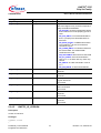
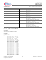
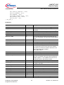
Linux® Compiler Flags . . . . . . . . . . . . . . . . . . . . . . . . . . . . . . . . . . . . . . . . . . . . . . . . . . . . . . . . . .
VxWorks® Compiler Flags . . . . . . . . . . . . . . . . . . . . . . . . . . . . . . . . . . . . . . . . . . . . . . . . . . . . . . .
Files to be included by the application software . . . . . . . . . . . . . . . . . . . . . . . . . . . . . . . . . . . . . .
System optional Macros . . . . . . . . . . . . . . . . . . . . . . . . . . . . . . . . . . . . . . . . . . . . . . . . . . . . . . . .
Device Driver Interface Overview . . . . . . . . . . . . . . . . . . . . . . . . . . . . . . . . . . . . . . . . . . . . . . . . .
IO-control Overview of Basic Interface . . . . . . . . . . . . . . . . . . . . . . . . . . . . . . . . . . . . . . . . . . . . .
IO-control Overview of Driver Initialization Interface . . . . . . . . . . . . . . . . . . . . . . . . . . . . . . . . . . .
Structure Reference of Driver Initialization Interface . . . . . . . . . . . . . . . . . . . . . . . . . . . . . . . . . . .
Enumerator Overview of Driver Initialization Interface . . . . . . . . . . . . . . . . . . . . . . . . . . . . . . . . . .
IO-control Overview of GPIO Interface . . . . . . . . . . . . . . . . . . . . . . . . . . . . . . . . . . . . . . . . . . . . .
Structure Overview of GPIO Interface . . . . . . . . . . . . . . . . . . . . . . . . . . . . . . . . . . . . . . . . . . . . . .
Function Overview of Driver Kernel Interface . . . . . . . . . . . . . . . . . . . . . . . . . . . . . . . . . . . . . . . .
Enumerator Overview of Driver Kernel Interface . . . . . . . . . . . . . . . . . . . . . . . . . . . . . . . . . . . . . .
IO-control Overview of Device Driver Interfaces . . . . . . . . . . . . . . . . . . . . . . . . . . . . . . . . . . . . . .
Constant Overview of Device Driver Interfaces . . . . . . . . . . . . . . . . . . . . . . . . . . . . . . . . . . . . . . .
Constant Reference for Device Driver Interfaces . . . . . . . . . . . . . . . . . . . . . . . . . . . . . . . . . . . . .
Structure Overview of Device Driver Interfaces . . . . . . . . . . . . . . . . . . . . . . . . . . . . . . . . . . . . . . .
Enumerator Overview of Non TAPI Interfaces . . . . . . . . . . . . . . . . . . . . . . . . . . . . . . . . . . . . . . . .
Function Overview of Non TAPI Interfaces . . . . . . . . . . . . . . . . . . . . . . . . . . . . . . . . . . . . . . . . . .
Preliminary User’s Manual
Programmer’s Reference
7
12
14
15
26
30
30
31
32
32
34
34
37
37
43
43
44
44
48
56
Revision 1.2, 2006-09-01
VINETIC®-CPE
Chip Set Family
CONFIDENTIAL
Preface
Preface
This document describes the VINETIC®-CPE device driver structure and usage. If not otherwise specified, the
description in this document applies to both two-channel and one-channel Version 2.2 devices of the
VINETIC®-CPE family.
To simplify matters, the following synonyms are used:
VINETIC®-CPE: Synonym used for the system consisting of VINETIC®-CPE codec together with SLIC-DC Version
1.2 or SLIC-E Version 2.2
VINETIC® driver: Synonym used for VINETIC®-CPE device driver.
Attention: TSLIC-E (PEF 4365) is a dual channel version of the SLIC-E (PEF 4265) with identical technical
specifications for each channel. Therefore whenever SLIC-E is mentioned in the specification,
TSLIC-E can also be deployed.
Organization of this Document
This document is organized as follows:
Chapter 1 provides an overview of the VINETIC®-CPE device driver. It gives all information needed to compile the
device driver, and it explains the configuration options.
Chapter 2 gives indications on how to integrate the device driver in the target system.
Chapter 3 guidelines for porting the device driver to different operating systems and hardware platforms.
Chapter 4 description of VINETIC®-CPE device driver interfaces.
Chapter 5 is the reference for the VINETIC®-CPE device driver interfaces.
Remarks
The present document includes guidelines for porting and integration of the VINETIC®-CPE device driver in
Chapter 2 and Chapter 3. The document VINETIC®-CPE device driver Porting and Integration Guide [12] has to
be considered obsolete.
Preliminary User’s Manual
Programmer’s Reference
8
Revision 1.2, 2006-09-01
VINETIC®-CPE
Chip Set Family
CONFIDENTIAL
1
Introduction
Introduction
This chapter gives an introduction to the device driver and how to compile it.
1.1
Introduction to the Device Driver
The VINETIC®-CPE device driver is a software module allowing the control of VINETIC®-CPE devices using the
Infineon TAPI V3.X: the device driver binary includes the VINETIC®-CPE implementation of the TAPI Low Level
layer. See Chapter 1.1.1 for more details and the document [5] for a description of TAPI interfaces.
In addition to the TAPI support, the VINETIC®-CPE device driver provides some interfaces for device’s control.
See Chapter 1.1.2 for more details.
1.1.1
Introduction to TAPI V3.x
With the introduction of version 3.0, TAPI is able to support the VoIP function of multiple Infineon devices/families,
including the latest IP-Phone device, VoIP processor and residential gateway SoC.
Infineon TAPI is implemented in two layers: TAPI High Level (HL), abstracting the features up to a none device
specific level, and TAPI Low Level (LL) implementing the device specific part (for example HW/FW access).
TAPI is able of supporting multiple Infineon devices belonging to different families. The most noticeable
architectural change in the TAPI V3.x is delivering TAPI HL as a separate driver, the TAPI LL is implemented in a
separate binary per supported device.
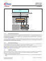
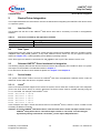
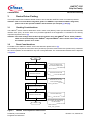
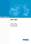
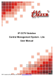
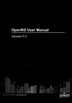
Both control and data paths use TAPI interfaces. Figure 1 provides an overview of the TAPI architecture, in the
particular configuration two different Infineon devices are controlled by TAPI1). As shown in the figure, three device
drivers must be loaded. To be noted that some Infineon device drivers include device specific commands (such
as device initialization) that, although not part of TAPI2), are passed through the TAPI OS interface. A classification
of TAPI and non-TAPI commands is done by the ioctl dispatcher (see Figure 1).
1) TAPI controls the telephony features of the Infineon device.
2) The device specific interfaces are documented in the next chapters.
Preliminary User’s Manual
Programmer’s Reference
9
Revision 1.2, 2006-09-01
VINETIC®-CPE
Chip Set Family
CONFIDENTIAL
Introduction
Application
Software
device driver
interface
TAPI
Driver
O S i/f
ioctl dispatcher
TAPI
High Level
Mapping to
TAPI Low Level
VoIP Subsystem
VoIP Subsystem
driver specific
TAPI Low Level
interfaces
HW Access & Interrupt
Event
Dispatcher
VINETIC
TAPI Low Level
HW Access & Interrupt
VoIP Subsystem
Driver
Figure 1
TAPI V3.x Architecture
1.1.2
Device Driver Interfaces
VINETIC driver
specific
interfaces
VINETIC
Driver
TAPI_VIN_architecture
The low level device driver might contain (non-TAPI) device specific interfaces. This set of ioctls can be used via
the same tapi file descriptors as the standard TAPI ioctls. The ioctls are transparently forwarded to the
corresponding low level device driver as shown in Fig 1. For a definition of these ioctls a low level _io.h file has to
be included by the application.
As shown in Figure 1, the VINETIC specific interfaces are implemented in the VINETIC®-CPE device driver and
the OS interfaces are registered by the TAPI driver. The advantage of this approach is that the application software
communicates only to one driver (the TAPI driver).
1.1.3
Device Driver Porting
With introductiion of VINETIC® device driver 1.0.x, the system- and board-specific code has been isolated to allow
an easy integration and upgrade of the VINETIC® device drivers in customer systems.
While operating system specific adaptions are still part of the device driver allocated in few files the board specific
adaptations like controlling the reset pin etc must be implemented in the BSP or in a "board"-driver.
Chapter 2 and Chapter 3 provide the details.
1.2
VINETIC® Access
Reflecting the different access modes the VINETIC®-CPE family is supporting, the VINETIC®-CPE device driver
offers a set of configure options to select the bus access mode of the specific system at compile time.
The following bus access modes are supported:
•
Parallel interface (8 bit Motorola / Intel mux / Intel demux): direct access (= => access provided by VINETIC®
driver)
Preliminary User’s Manual
Programmer’s Reference
10
Revision 1.2, 2006-09-01
VINETIC®-CPE
Chip Set Family
CONFIDENTIAL
•
Introduction
Serial (SPI): Access via additional SPI device-driver module (not provided by Infineon)
These interfaces are implemented in the files drv_vinetic_access.h/c and assure the sequential read/write of
packet and command data to and from the VINETIC® device.
1.2.1
VINETIC® Parallel Access
The support of the parallel access does not require any user-specific adaptation. The macros are properly set at
compile time and enable access to memory-mapped registers and mailboxes. The required compiler options for
VxWorks® are listed in Table 1. The required configure options for Linux® are listed in Table 2.
In [1] a complete list of corresponding configure options can be found.
1.2.2
VINETIC® SPI Access
As for the parallel access, the support of SPI interface is enabled with the compiler switch DVIN_ACC_MODE=SPI or the corresponding configure option --with-access-mode=SPI.
When compiled this way, the VINETIC® driver provides generic SPI low-level routines (drv_vinetic_access.c/h)
and expects some macros to be set in the user configuration header file (see Chapter 3.9). These macros are:
•
•
•
SPI_MAXBYTES_SIZE, which indicates how many bytes can be read or written in one go via the SPI interface
SPI_CS_SET (devnr, high_low), which sets the device SPI chip select to low or to high
Spi_ll_read_write (txptr, txsize, rxptr, rxsize), which is mapped to the exported system low-level SPI read/write
routine
Once these adaptations are done, the VINETIC® SPI access will work correctly and completely with the VINETIC®
driver.
Attention: The VINETIC®-CPE Version 2.2 chip set makes it possible to configure SPI addresses via pin
strapping. This address has to be passed to the VINETIC® driver with the
FIO_VINETIC_BASICDEV_INIT ioctl as the base address. When only one device is attached to
the SPI bus and pin strapping is not used, the base address must be set to 0x1F.
Attention: The VINETIC®-CPE Version 2.2 chip set uses SPI mode 3. Please refer to [1] for SPI mode
details.
1.3
Compilation
This chapter describes how to compile the TAPI device driver for Linux® (kernel 2.4) and VxWorks® (version 5.4).
For Linux®, the GNU toolchain (autoconf, automake) is used. For VxWorks®, the Tornado project files are required.
To retrieve the device driver sources and to obtain the execution rights and directory structure, the following
command has to be used. It will extract all sources into a subdirectory.
tar xvzf drv_vinetic-1.2.x.x.tar.gz
In case of the new Linux® native self extractor:
s./drv_vinetic-1.2.x.x.sh
read and confirm the license agreement by typing "yes".
1.3.1
Linux®
Building the device driver is done in two steps:
•
•
Go to the directory where you extracted the sources and type in ./configure with the options described in
Table 1 and then
Execute make or make install
Prerequisite are: the toolchain is in place, the path to the cross-compiler is included in the PATH and the availability
of path to the Linux® kernel header files (using compiler switch --enable-kernelincl=<include path>).
Preliminary User’s Manual
Programmer’s Reference
11
Revision 1.2, 2006-09-01
VINETIC®-CPE
Chip Set Family
CONFIDENTIAL
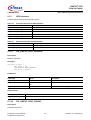
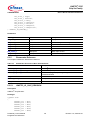
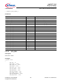
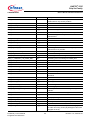
Table 1
Introduction
Linux® Compiler Flags
Option
Description
Required
--enable-debug
--disable-debug
Enable/disable debug messages.
Optional
--enable-kernelincl
Set the Linux® kernel include path.
Always
--enable-lt
--disable-lt
Enable/disable TAPI line testing services
Optional
--enable-voice
--disable-voice
Enable/disable TAPI Voice support.1)
Optional
--enable-dtmf
--disable-dtmf
Enable/disable TAPI DTMF detection support.1)
Optional
--enable-cid
--disable-cid
Enable/disable TAPI Caller ID support.1)
Optional
--enable-fax
--disable-fax
Enable/disable TAPI T.38 Fax support.1)
Optional
--enable-udp-redirect
Enable QoS - quality of service and UDP redirection.
Optional
--enable-trace
Enable runtime traces.
Optional
--with-access-mode=<value>
Value is the desired µC access mode for your system,
which should be one of the following constants:
INTEL_MUX, INTEL_DEMUX , MOTOROLA, and SPI.
Always
--with-access-width=<value>
Value is the desired µC access width the device driver
Optional
does. It should be either 16 (default) or 8.
From the device driver’s view, all accesses to the
VINETIC® are 16-bit (register size). The VINETIC®-CPE
provides only a 8-bit bus interface, which still leaves two
choices despite the access mode:
• The VINETIC®-CPE driver still does 16-bit accesses
and the bus controller split each access in two 8-bit
accesses (assuring the correct timing) or
• If the bus controller cannot be configured to split 16bit accesses as described above, the VINETIC®-CPE
driver to do only 8-bit accesses.
In either case, the device driver will do the accesses in
accordance to controller’s endianess. Refer to option -enable-byte-swap if your controller’s endianess does not
match the bus endianess.
The SPI interface is specified for 8-bit accesses only.
--enable-byte-swap
Optional
This is a special option for the VINETIC®-CPE device
driver to enable byte swapping inside the VINETIC®-CPE.
This option is intended to support little-endian bus
accesses (such as Intel) in combination with big-endian
controllers and vice versa.
Example: MIPS controller in big-endian mode and the bus
controller performs little-endian bus accesses. In this
case, byte swapping is required and can be done very
efficiently by the VINETIC®-CPE device. This eliminates
the need for modifying the device driver code.
Preliminary User’s Manual
Programmer’s Reference
12
Revision 1.2, 2006-09-01
VINETIC®-CPE
Chip Set Family
CONFIDENTIAL
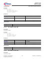
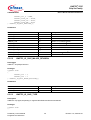
Table 1
Introduction
Linux® Compiler Flags (cont’d)
Option
Description
Required
--with-max-devices=val
Maximum VINETIC devices to support (default = 1)
Optional
--enable-polling
Enable polling support.
Important - the corresponding low level device drivers
have to be compiled with --enable-polling as well.
Optional
1) Per default voice, dtmf, cid and fax are enabled. This will change in a next TAPI version.
1.3.1.1
Loading of the TAPI Modules and Registration
TAPI driver and low-level device drivers (including TAPI LL) are defined to be implemented as kernel modules,
which can be inserted or removed from the kernel dynamically. The device drivers must be loaded after the High
Level TAPI is loaded.
On insmod the version information of the Device driver is displayed on the console.
If CONFIG_DEVFS_FS is supported, device nodes are created by the High Level TAPI on insmod of the low-level
driver. The template is /dev/<devName>/<deviceNumber><channelNumber>
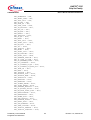
Example - Registration
/* TAPI Module is built as “drv_tapi” */
# insmod drv_tapi
/* Now load TAPI LL part with default parameters: */
/* Use default major number and device node name */
/* drv_vinetic is the TAPI LL for the VoIP subsystem */
# insmod drv_vinetic
/* As an alternative, TAPI LL is loaded using customer parameters */
/* major = device driver major number */
/* devName = device node name to be used */
# insmod drv_vinetic major=244 devName=vinetic
1.3.1.2
Support of proc File System
If CONFIG_PROC_FS is supported, the proc file system reports the list of successfully registered low-level device
drivers and version of the TAPI.
Example - Proc File System
/* Retrieves the registered low level drivers, example */
# cat /proc/driver/tapi/registered_drivers
Driver
version
major
devices
devname
========================================================
VINETIC
1.2.x.x
230
1
/dev/vinetic
/* Retrieves the version information of High Level TAPI, example */
# cat /proc/driver/tapi/version
TAPI Driver, Version 3.2.0.1
Compiled on Feb 20 2006, 16:58:09 for Linux kernel 2.4.31-tqm-dpram-ralph
Preliminary User’s Manual
Programmer’s Reference
13
Revision 1.2, 2006-09-01
VINETIC®-CPE
Chip Set Family
CONFIDENTIAL
1.3.2
Introduction
VxWorks®
It is expected that user has knowledge about Tornado (compiling, configuring, using targed server, tftp, etc.) and
that VxWorks® sources are available.
Building image:
Add drv_vinetic.wpj and drv_tapi.wpj to the workspace and build.
Call the two exported functions from the BSP in order to initialize and link the two resulting .a files to the kernel
image: TAPI_DeviceDriverInit() and VINETIC_DeviceDriverInit().
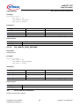
Table 2
VxWorks® Compiler Flags1)2)
Flag
Description
Required
®
3)
-DVIN_2CPE
Enable VINETIC -CPE support.
Always
-DTAPI
Enable TAPI Interface.
Always
-DTAPI_DTMF
Enable/disable TAPI DTMF detection support.
Disabled by default.
Optional
-DTAPI_CID
Enable/disable TAPI Caller ID support.
Disabled by default.
Optional
-DTAPI_VOICE
Enable/disable TAPI voice support.
Disabled by default.
Optional
-DTAPI_FAX_T38
Enable/disable TAPI T.38 Fax support.
Disabled by default.
Optional
-DTAPI_LT
Enable/disable TAPI line testing services.
Disabled by default.
Optional
-DTAPI_GR909
Enable TAPI GR909 tests.
Disabled by default.
Optional
-DVIN_ACCESS_MODE=1
Define the access mode:3)
• 1 - VIN_ACCESS_MODE_MOTOROLA
• 2 - VIN_ACCESS_MODE_INTEL_MUX
• 3 - VIN_ACCESS_MODE_INTEL_DEMUX
• 4 - VIN_ACCESS_MODE_SPI
Always
-DVIN_ACCESS_WIDTH=16
Defines 8 or 16-bit access.3)
Always
-DDEBUG
Enable debug messages.
Optional
-DENABLE_TRACE
Enable trace outputs in general.
Optional
-DRUNTIME_TRACE
Enable runtime traces.
Optional
-DENABLE_LOG
Enable log (errors) outputs in general.
Optional
-DTAPI_POLL
Enable polling support.
Optional
Important - the corresponding low level device drivers have
to be compiled with -DTAPI_POLL as well.
1) Here only flags for compiling the driver are described, not VxWorks® related flags.
2) If flag is not present then feature is disabled.
3) Used only for drv_vinetic project
Preliminary User’s Manual
Programmer’s Reference
14
Revision 1.2, 2006-09-01
VINETIC®-CPE
Chip Set Family
CONFIDENTIAL
2
Device Driver Integration
Device Driver Integration
This chapter addresses the issues which must be considered when integrating the VINETIC®-CPE device driver
on a specific system.
2.1
Interface Files
This chapter lists the files of the VINETIC®-CPE device driver that is necessary to include in the application
software.
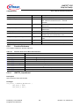
Table 3
Files to be included by the application software
Filename
Description
vinetic_io.h
VINETIC®-specific ioctl interface
drv_tapi_io.h
TAPI ioctl interface
2.2
Data Types
Original data types are used for operating system-specific functions and variables within the operating system
adaptation files <drv_vinetic_<os>.c>. In any other VINETIC® driver source file, only IFX types are used as
defined in Chapter 5.3.1. It helps portability across different operating systems.
Note: These types are defined in the header file <ifx_types.h> that is part of the released source code.
Relevant VINETIC® Driver Interfaces for Integration
2.3
The following chapters describe the relevant interfaces used for the integration of the VINETIC® driver in a system
with respect to the hardware considerations listed in Chapter 3.
For a reference of all device driver interfaces please see Chapter 4 and Chapter 5.
2.3.1
Device Nodes
The system uses device nodes to access the VINETIC®-CPE from the application. Different device nodes are
defined to access either the device or a specific channel.
2.3.1.1
Linux®
If the Linux® kernel includes support for the device file system, device nodes are created by the TAPI subsystem
(for the low level device driver) on insmod. Otherwise, the device nodes must be created manually using the
mknod command. For example, with VINETIC®-CPE:
mknod
mknod
mknod
mknod
mknod
/dev/vin10
/dev/vin11
/dev/vin12
/dev/vin13
/dev/vin14
c
c
c
c
c
230
230
230
230
230
10
11
12
13
14
In this example, the “major” number 230 was chosen for the VINETIC® device, while the “minor” number is used
to identify the different channels.
Attention: Currently VINETIC®-CPE device driver uses the same device nodes and major number as the
VINETIC® family device driver. The default major number is set to 230, it can be changed
dynamically during insmod with "insmod drv_vinetic major=<MajorNumber>".
Preliminary User’s Manual
Programmer’s Reference
15
Revision 1.2, 2006-09-01
VINETIC®-CPE
Chip Set Family
CONFIDENTIAL
2.3.1.2
Device Driver Integration
VxWorks®
In case of VxWorks® the device nodes are created automatically (with the same names as used for Linux®) - no
manual steps required.
2.3.2
VINETIC® Basic Device Initialization
The first step to be done by the VINETIC® driver is an initialisation on each device. This has to be initiated by the
application software. For this purpose, the VINETIC® driver has a dedicated interface called
FIO_VINETIC_BASICDEV_INIT which expects the following parameters:
1. The VINETIC® device physical base address, which is known by the system. This is applicable both for parallel
and SPI access (see Chapter 2.3),
2. The VINETIC® device irq line number known by the system. If the parameter is negative, polling mode is
assumed.
Attention: The access mode is set at compile time with the compiler switch DVIN_ACCESS_MODE=<access_mode> or the corresponding configure option --with-accessmode=<access_mode>. Please take care that the selected access mode matches the access
mode used on your system. Ask your hardware designer if you are unsure.
During the basic device initialization, the following actions take place:
1. Device Base address pointer is set for the access (Parallel and SPI access modes).
2. When in interrupt mode, the interrupt routine is registered by the operating system.
After a successful basic initialization, the next step must be the TAPI initialization.
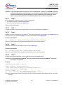
2.3.3
VINETIC® Device Reset
When the application decides to reset the device (see Chapter 3.2), the VINETIC® driver must be involved
because the device context data inside the VINETIC® driver must also be reset. This operation is done via the
command FIO_VINETIC_DEV_RESET.
Note: If a basic device initialization (see Chapter 2.3.2) has been performed before, it is not required to call
FIO_VINETIC_BASICDEV_INIT because these basic settings are not reset.
Example
The following example resets the VINETIC® device number 0. Every function prefixed with <system_> must be
provided by the system interface. It is assumed that the file descriptor of this VINETIC® device is available in the
example.
/* activate reset of vinetic device 0 */
ret = system_activate_reset (0);
/* deactivate reset of vinetic device 0 */
if (ret == IFX_SUCCESS)
ret = system_deactivate_reset (0);
/* reset internal device data in VINETIC® driver */
if (ret == IFX_SUCCESS)
ret = ioctl (fdVinDev [0], FIO_VINETIC_DEV_RESET, 0);
2.4
VINETIC® Driver Integration Details
The VINETIC® driver controls the communication with the VINETIC® chip and does not take care of any hardware
or system configuration.
Therefore, all system- or platform-relevant initialization and control tasks have to take place in separate software
modules that must be implemented when integrating the VINETIC® driver. This makes the VINETIC® driver
platform-independent and reduces the porting issues on all platforms.
Preliminary User’s Manual
Programmer’s Reference
16
Revision 1.2, 2006-09-01
VINETIC®-CPE
Chip Set Family
CONFIDENTIAL
Device Driver Integration
The following sections describe the steps required for the complete integration of the VINETIC® driver on a new
system.
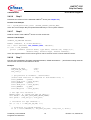
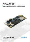
2.4.1
Driver Integration - Flow Overview
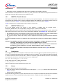
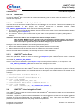
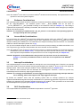
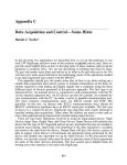
The initialization of the system (access mode, clock rate, interrupt line, chip select) must take place at the system
level before the VINETIC® driver is integrated. The VINETIC® driver is initialized in two steps, basic device
initialization and TAPI initialization. Figure 2 shows the complete integration flow:
For the reset flow please refer to Figure 3.
Before starting, make sure that the
power and the generated clocks are
conform to the values indicated in
datasheets
Start
Initialize System
(Board, Platform)
This is done at system level and
comprises:
- access mode settings
- chip select settings
- interrupt line configuration
For each device on system
Activate reset line for this
VINETIC device
Initialize this VINETIC Vinetic
device using
FIO_VINETIC_BASICDEV_INIT
For each device, following system
parameters are needed:
- device access mode
- device physical base address
- device irq line number
Deactivate reset line for this
VINETIC device
End For each device on system
From here on, the vinetic driver is
operational
Vinetic chip Initialization
(FW, CRAM, …), ie via Tapi
Initialization
Application initializes VINETIC chip
(i.e Tapi Init)
End
From here on, the vinetic chip is
operational
Vinetic_driver_integration_flow
Figure 2
VINETIC® Driver Integration Flow
2.4.2
Driver Integration - Detailed Steps
This support can be provided in the form of a system driver (commonly called board driver) or in the form of a
BSP1). The following steps from 0 to 7 lead to a successful integration of the VINETIC® driver on a system.
1) BSP = Board Support Package. This support can be provided as an example by or integrated to the operating system used.
Preliminary User’s Manual
Programmer’s Reference
17
Revision 1.2, 2006-09-01
VINETIC®-CPE
Chip Set Family
CONFIDENTIAL
Device Driver Integration
Attention: In the description below, functions or macros prefixed with <system> or <SYSTEM> represent
a pseudocode example of functionalities required by the system software. This does not mean
that all macros/functions implemented by the system software must be prefixed as stated
above. It is only important that the functionality behind the pseudocode is granted.
2.4.2.1
Step 0
Before setting up the VINETIC® driver, it must be verified that:
•
•
The VINETIC® device is powered appropriately.
The clocks are set properly (see Chapter 3.1).
Please refer to [1] for details.
2.4.2.2
Step 1
Compile the VINETIC® driver with the appropriate access mode as specified in Chapter 2.3.
2.4.2.3
Step 2
Initialize the system depending on the VINETIC® chip used by setting the access mode (see Chapter 3.4), the
chip selects, the clock rate (see Chapter 3.1), and the interrupt lines (see Chapter 3.5).
Pseudo Code Example
ret = system_init (SYSTEM_ACCESS_MODE, SYSTEM_2048KHZ_CLOCKRATE);
Note: This is an example. May be implemented differently in user’s system software.
2.4.2.4
Step 3
Activate the reset line for each VINETIC® device (see Chapter 3.2).
Pseudo Code Example
ret = system_activate_reset (SYSTEM_VINETIC_DEVICE_ONE);
Note: This is an example. May be implemented differently in user’s system software.
2.4.2.5
Step 4
Do basic device driver initialization of each VINETIC® device (see Chapter 2.3.2).
Attention: It is assumed that the VINETIC® driver is already installed and that all VINETIC® devices file
descriptors are available.
Example
VINETIC_BasicDeviceInit_t devInit;
memset (&devInit, 0, sizeof(devInit));
/* set access mode according to VIN_ACCESS enumeration */
devInit.nBaseAddress = 0xC0010000;
devInit.nIrqNum = 12;
ret = ioctl (fdVinDev, FIO_VINETIC_BASICDEV_INIT, &devInit);
Note: This implementation can be used as generic code to basically initialize each VINETIC® device. Values are
examples.
Preliminary User’s Manual
Programmer’s Reference
18
Revision 1.2, 2006-09-01
VINETIC®-CPE
Chip Set Family
CONFIDENTIAL
2.4.2.6
Device Driver Integration
Step 5
Deactivate the reset line for the initialized VINETIC® device (see Chapter 3.2).
Pseudo Code Example
ret = system_deactivate_reset (SYSTEM_VINETIC_DEVICE_ONE);
Note: This is an example. May be implemented differently in user’s system software.
2.4.2.7
Step 6
Read the version of the VINETIC® device as a first access test.
Generic Code Example
VINETIC_IO_VERSION devVers;
memset (&devVers, 0, sizeof(devVers));
ret = ioctl (fdVinDev, FIO_VINETIC_VERS, &devVers);
if (ret == IFX_SUCCESS)
printf ("VINETIC [version 0x%2X, type 0x%2X, channels %d] ready!\n\r",
devVers.nChip, devVers.nType, devVers.nChannel);
Note: This implementation can be used as generic code to read the version of each VINETIC® device.
2.4.2.8
Step 7
Execute TAPI initialization (Firmware download/activation, CRAM download etc....) and feed the analog channels
lines for each channel on the VINETIC® device.
Example
VINETIC_IO_INIT
IFX_TAPI_CH_INIT_t
IFX_uint8_t
vinit;
Init;
i = 0;
/* get pointers to firmware / coefficients
(either read from file or compiled in from header file) */
vinit.pPRAMfw
= pPram;
vinit.pram_size = <size_bytes>;
vinit.pDRAMfw
= pDram;
vinit.dram_size = <size_bytes>;
vinit.pBBDbuf
= p_bbd;
vinit.bbd_size = <size_bytes>;
/* Set tapi init structure */
memset(&Init, 0, sizeof(IFX_TAPI_CH_INIT_t));
Init.nMode = IFX_TAPI_INIT_MODE_VOICE_CODER;
Init.pProc = (IFX_void_t*) &vin_proc;
/* Initialize all tapi channels */
for (i = 0; i <= MAX_SYS_CH_RES; i++)
{
/* Initialize all system channels */
if (0 != ioctl(fdDevCh[i], IFX_TAPI_CH_INIT, (IFX_int32_t) &Init))
Preliminary User’s Manual
Programmer’s Reference
19
Revision 1.2, 2006-09-01
VINETIC®-CPE
Chip Set Family
CONFIDENTIAL
Device Driver Integration
{
break;
}
/* Set appropriate feeding on all (analog) line channels */
if (i < MAX_SYS_LINE_CH)
{
/* Set line in standby */
if (IFX_SUCCESS != ioctl(fdDevCh[i], IFX_TAPI_LINE_FEED_SET,
IFX_TAPI_LINE_FEED_STANDBY))
{
break;
}
}
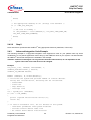
2.4.2.9
Step 8
Driver interface is operational with VINETIC® using appropriate functions (read/write, TAPI ioctls).
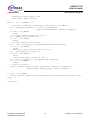
2.4.3
Advanced Integration Code Example
The following example is a copy/paste integration code supposed to work on your platform with only small
modifications. It is a pseudo application code to bring up the VINETIC® driver in your system. It is assumed that
all VINETIC® devices file descriptors are available in the example.
Attention: Infineon Technologies can not guarantee that this code will work, as it is dependent on the
system. The order of the calls must not be changed.
Example
IFX_int32_t ret, nDevNum, nAccessMode, i;
VINETIC_BasicDeviceInit_t devInit;
VINETIC_IO_VERSION devVers;
memset (&devInit, 0, sizeof(devInit));
memset (&devVers, 0, sizeof(devVers));
/* initialize the system and get back number of vinetic devices.
During this initialization, following will be initialized:
- access mode
- clock rate
- chip select(s)
- interrupt line
*/
ret = system_init (&nDevNum);
if (ret == IFX_ERROR)
{
printf (“system initialization fails\n\r“);
return ret;
}
/* in case of successful init, for all devices in the system:
- read basic parameters from system interface
- activate vinetic device reset line
- do vinetic basic device initialization
Preliminary User’s Manual
Programmer’s Reference
20
Revision 1.2, 2006-09-01
VINETIC®-CPE
Chip Set Family
CONFIDENTIAL
Device Driver Integration
- deactivate vinetic device reset
- read vinetic device version
*/
for (i = 0; i < nDevNum; i++)
{
/* get basic parameters: access mode, base address, irq number */
ret = system_get_parameter (i, &(devInit.AccessMode),
&(devInit.nBaseAddress), &(devInit.nIrqNum));
if (ret == IFX_ERROR)
break;
/* activate vinetic device reset line */
ret = system_activate_reset (i);
if (ret == IFX_ERROR)
break;
/* do basic device initialization */
ret = ioctl (fdVinDev[i], FIO_VINETIC_BASICDEV_INIT, &devInit);
if (ret == IFX_ERROR)
break;
/* deactivate vinetic device reset line now */
ret = system_deactivate_reset (i);
if (ret == IFX_ERROR)
break;
/* read vinetic device version as test */
ret = ioctl (fdVinDev[i], FIO_VINETIC_VERS, &devVers);
if (ret == IFX_ERROR)
break;
/* print out version */
printf ("VINETIC [version 0x%2X, type 0x%2X, channels %d] ready!\n\r",
devVers.nChip, devVers.nType, devVers.nChannel);
}
if (ret == IFX_ERROR)
printf (“please go back to the documentation and double check you didn't miss a
step...“);
return ret;
Preliminary User’s Manual
Programmer’s Reference
21
Revision 1.2, 2006-09-01
VINETIC®-CPE
Chip Set Family
CONFIDENTIAL
3
Device Driver Porting
Device Driver Porting
This chapter addresses hardware-related issues to ensure that the VINETIC® driver runs without problems.
Attention: This is not a hardware integration guide. For VINETIC® chip-related hardware integration,
please refer to the specific hardware documentation (for example [1] and [3]).
3.1
Clocking Considerations
The VINETIC® device needs at least three clocks: master clock (MCLK), frame synchronization (FSC) and PCM
interface clock (PCL). All clocks have to be provided regardless of the application. For details on the clocking
requirements please refer to [1].
Attention: The clock settings must be done properly before using the VINETIC® Driver. Clock problems
affect correct functionality of the VINETIC® chip and VINETIC® driver. Please refer to DEV_ERR
for hardware specific error codes.
3.2
Reset Considerations
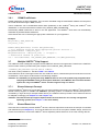
For details on the VINETIC®-2CPE/-1CPE reset behaviour please refer to [1].
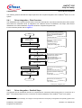
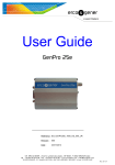
It is mandatory to respect the reset active time (at least 20 µs) and the reset inactive time (at least 2 ms); otherwise
the correct operation of the VINETIC® chip can not be guaranteed. The recommended software flow is depicted
in Figure 3.
Start
In case of a shared reset
line, all devices will be reset!
Activate Device Reset Pin
At least 20 microseconds
Wait Reset active time
Reset activation and
deactivation can be done
in two separated flows.
Deactivate Device Reset Pin
At least 2 milliseconds
Wait Reset inactive time
Once this whole reset sequence
is completed, the VINETIC chip
can be accessed.
End
Vinetic_reset_operation
Figure 3
VINETIC® Reset Operation Software Flow
Preliminary User’s Manual
Programmer’s Reference
22
Revision 1.2, 2006-09-01
VINETIC®-CPE
Chip Set Family
CONFIDENTIAL
Device Driver Porting
Note: The VINETIC® driver does not provide a VINETIC® hardware reset functionality. The implementation of this
operation is left to the system integrator.
3.3
Endianess Considerations
The operating system header file which contains the endianess information (little/big endian) must be included in
the file <sys_drv_ifxos.h>. The hardware generic macro __BYTE_ORDER must be set either to
__LITTLE_ENDIAN or to __BIG_ENDIAN according to the endianess used (see Chapter 3.1). This setting is
important and required for the handling of 8-bit data, which should be converted to other data types (for example
8-bit to 16-bit, 8-bit to 32-bit).
Attention: It is mandatory to update the file <sys_drv_ifxos.h> in case that the used operating system is
not supported by the driver package.
3.4
Access Mode Considerations
For programming the VINETIC® and performing data/packet transfer to/from the VINETIC®, either a parallel
interface or a serial microcontroller interface can be used. Additionally, the VINETIC® is equipped with a PCM
interface enabling the establishment of a PCM/TDM voice samples exchange with other devices. For a detailed
VINETIC® interface description please refer to [1].
It is up to the hardware designer either to set the access mode by fixed pin settings of IFSEL0 and IFSEL1 or to
use a logic device (for example CPLD) between the microcontroller and the VINETIC®.
Note: The VINETIC® driver expects the selected access mode via a dedicated interface for its internal mappings
at initialization time (see Chapter 2.3.2). To support the serial microcontroller interface (SPI), the VINETIC®
driver requires the implementation of specific macros in its user configuration file (see Chapter 3.9).
Attention: Regardless of the PCM Interface being used or not, all clock sources (as described in
Chapter 3.1) must be provided all the time to ensure the correct operation of the VINETIC®
device.
3.5
Interrupt Considerations
The hardware designer connects the VINETIC® interrupt line to the microcontroller used. Therefore, the interrupt
line number used by the microcontroller must be communicated to the VINETIC® driver, so that it can register its
interrupt routine. This is done during the VINETIC® driver initialization time (see Chapter 2.3.2).
The VINETIC® driver assumes that the interrupts are level-triggered. Therefore, it does not provide any
acknowledgement as needed by edge-triggered interrupts.
Attention: It is strongly recommended to use level-triggered interrupt to avoid losing interrupts while the
line is disabled, which often happens with edge-triggered interrupts.
By default, the VINETIC® driver uses the operating system calls for interrupt operations (for example
register/enable/disable/unregister interrupts). Nevertheless, for systems that implement a logic device for interrupt
handling (for example FPGA controlling shared interrupt line), the VINETIC® driver provides a set of macros that
must be adapted for this purpose (see Chapter 3.8 and Chapter 3.9).
3.6
SLIC Considerations
This chapter addresses (software) considerations dependent on the SLIC1) type used.
1) SLIC = Subscriber Line Interface Circuit
Preliminary User’s Manual
Programmer’s Reference
23
Revision 1.2, 2006-09-01
VINETIC®-CPE
Chip Set Family
CONFIDENTIAL
3.6.1
Device Driver Porting
CRAM Coefficients
CRAM coefficients are SLIC-dependent. They must be calculated using the VINETICOS software and are part of
the overall download image in BBD1) format .
These coefficients can be downloaded device-wise (broadcast) to the VINETIC® during the VINETIC® TAPI
initialization, or channel-wise with the interface FIO_VINETIC_BBD_DOWNLOAD.
Downloading CRAM coefficients is done in the user application. The VINETIC® driver does not automatically
download any default CRAM coefficients.
Note: Please take care of selecting the appropriate coefficients for your application.
Example
bbd_format_t bbd_download;
IFX_int32_t ret;
memset(&bbd_download,0, sizeof (bbd_download));
/* fill download structure whith appropriate pointer and size */
bbd_download.buf = bbd_file_ptr;
bbd_download.size = bbd_file_size; /* in bytes */
/* download on channel of given fd */
ret = ioctl(fdVinChan, FIO_VINETIC_BBD_DOWNLOAD,(int)&bbd_download);
3.7
Multiple VINETIC® Chip Support
The VINETIC® driver is designed to support several VINETIC® devices on a single board. Therefore, the VINETIC®
device number must be provided using the compiler macro VINETIC_MAX_DEVICES:
-DVINETIC_MAX_DEVICES=<system device number>.
The value is set by default to 1. See also Table 1 and Table 2.
If the VINETIC® driver must support more than one VINETIC® device, shared interrupts and reset lines come into
consideration. These topics are discussed in the following chapters.
Attention: It is mandatory to specify how many VINETIC® devices are on the system being integrated when
compiling the VINETIC® driver for that system. Otherwise, the VINETIC® driver assumes that the
system has only one VINETIC® device and also supports only one device.
3.7.1
Shared Interrupt Concept
If several VINETIC® devices are connected to only one microcontroller interrupt line, the VINETIC® driver provides
shared interrupt support for Linux® and VxWorks® operating systems. If instead the shared interrupt line is
controlled by a logic device (for example FPGA device), the VINETIC® driver provides a set of macros that must
be adapted accordingly (see Chapter 3.5 and Chapter 3.9).
Attention: The shared interrupt support implementation must be done for all currently unsupported
operating systems (see Chapter 3.1 for more details).
3.7.2
Shared Reset Line
If the reset line is shared by several VINETIC® devices, all these chips will be reset when the reset pin is activated
and deactivated (see Chapter 3.2). This must be taken into account in the system software design, which must
provide a mechanism to reset each VINETIC® device separately without influence on the other running devices.
1) BBD = Block Based Download
Preliminary User’s Manual
Programmer’s Reference
24
Revision 1.2, 2006-09-01
VINETIC®-CPE
Chip Set Family
CONFIDENTIAL
3.8
Device Driver Porting
Other System Considerations
This chapter includes some VINETIC® driver system considerations which make it necessary to implement a
system abstraction layer in addition to the VINETIC® driver interfaces for the integration that are already provided.
The reason for this is that these system considerations could not be addressed by means of the provided
interfaces.
Considering system differences, a list of several usable (optional) system macros was defined.
The VINETIC® driver uses these macros for special system parameters which can be overruled by a user
configuration file (see Chapter 3.9).
This ensures the flexibility needed by the VINETIC® driver, which has to support several system implementations
without increased complexity.
List of the (optional) system macros (set at compile time):
•
•
•
VIN_DISABLE_IRQLINE(...)/ VIN_ENABLE_IRQLINE(...)
These macros are intended to map the enable/disable IRQ lines routines for systems not using the operating
system methods for this action (for example FPGA device controls interrupt handling). They are by default
mapped to the appropriate operating system routines.
VIN_DISABLE_IRQGLOBAL(...)/ VIN_ENABLE_IRQGLOBAL(...)
These macros are intended to map the enable/disable global IRQ routines for systems not using the operating
system methods for this action (for example FPGA device controls interrupt handling). They are by default
mapped to the appropriate operating system routines. When used, all interrupt sources are disabled or enabled
on the microcontroller.
VIN_SYS_REGISTER_INT_HANDLER(...) / VIN_SYS_UNREGISTER_INT_HANDLER(...)
These macros are intended for the registration / deregistration of the interrupt handler when the operating
system routines are not suitable for this purpose (for example user implements his own assembler routines for
theses purposes). They are by default mapped to the operating system routines (see Chapter 3.1).
3.9
VINETIC® Driver System Configuration File
The VINETIC® driver provides a system abstraction layer header file in which several (optional) system-specific
macros can be redefined if needed to ensure full support of the system being integrated (for example: macros
defined in Chapter 3.8).
This file, called <drv_config_user.h>, is system-specific (which means not common) and therefore must be
located in the system build directory.
The VINETIC® driver considers the macros defined in this file only if compiled with the specific compiler switch
’-DENABLE_USER_CONFIG’.
Note: On systems using the configure/automake tools, this macro is set when the argument --enable-user-config
is passed to the configure/automake script.
A template of this file, called <drv_config_user.default.h>, is available with the released source code. This file
contains system macros that can be adapted accordingly. Once adapted, the file must be placed in the target build
directory and renamed to <drv_config_user.h>.
A direct application of this file is the system-dependent SPI support (see Chapter 3.4).
Table 4 shows an overview of system-relevant macros defined in the file. For more details (for example: about
macro parameters), please refer to the commented source file.
Preliminary User’s Manual
Programmer’s Reference
25
Revision 1.2, 2006-09-01
VINETIC®-CPE
Chip Set Family
CONFIDENTIAL
Table 4
Device Driver Porting
System optional Macros
Name
Description
Error Setting Macro
SET_ERROR(...)
Macro to signal and set an error. Useful to generate a trigger
signal during hardware debugging.
SPI Access Support Macros (usage enabled with -DVIN_SPI)
SPI_MAXBYTES_SIZE
SPI buffer size in bytes (8-bit) according to the SPI driver.
SPI_CS_SET(...)
Macro to set/unset SPI chip select.
spi_ll_read_write(...)
Macro mapping the low-level SPI read/write routine, exported for
example by an SPI driver.
Interrupt Operations Support Macros (in case OS methods are not suitable)
VIN_DISABLE_IRQLINE(...)
Macro to disable the interrupt line specified, by default set to OS
method (see Chapter 3.1).
VIN_ENABLE_IRQLINE(...)
Macro to enable the interrupt line specified, by default set to OS
method (see Chapter 3.1).
VIN_DISABLE_IRQGLOBAL(...)
Macro to disable the global interrupt, by default set to OS method
(see Chapter 3.1), used in polling mode to lock high priority
tasks.
VIN_ENABLE_IRQGLOBAL(...)
Macro to enable the global interrupt, by default set to OS method
(see Chapter 3.1), used in polling mode to unlock previously
locked high priority tasks.
VIN_SYS_REGISTER_INT_HANDLER(...)
Macro that maps the function taking care of the interrupt handler
registration, by default set to OS method implemented in OS file
(see Chapter 3.1).
VIN_SYS_UNREGISTER_INT_HANDLER(...) Macro that maps the function taking care of the interrupt handler
unregistration, by default set to OS method implemented in OS
file (see Chapter 3.1).
Preliminary User’s Manual
Programmer’s Reference
26
Revision 1.2, 2006-09-01
VINETIC®-CPE
Chip Set Family
CONFIDENTIAL
4
Description of the Device Driver Interfaces
Description of the Device Driver Interfaces
This chapter introduces VINETIC®-CPE device driver interfaces.
4.1
Device Initialization
It follows a list of device driver interfaces required for VINETIC®-CPE hardware and device driver initialization.
Usage examples are given in Chapter 2.3.
•
•
FIO_VINETIC_BASICDEV_INIT is required for hardware initialization, see also Chapter 2.3.2.
FIO_VINETIC_DEV_RESET is required after device reset, see also Chapter 2.3.3.
4.2
Miscellaneus Interfaces
It follows a list of miscellaneous device driver interfaces.
•
•
FIO_VINETIC_VERS should be used to know the VINETIC®-CPE device version, see also Chapter 2.4.2.7
for an example.
FIO_VINETIC_LASTERR can be used to know the cause of the error reported by an ioctl, the errors are
defined in enum DEV_ERR.
4.3
General-Purpose IOs
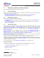
The VINETIC®-CPE device driver’s GPIO module allows access to the VINETIC®-CPE GPIO pins1), ioctl and
function interfaces are provided. To avoid concurrent access, the GPIO pin needs to be reserved
FIO_VINETIC_GPIO_RESERVE (or VINETIC_GpioReserve) before it can be used. Any subsequent try to
reserve this pin will fail until it is released explicitly by FIO_VINETIC_GPIO_RELEASE (or
VINETIC_GpioRelease).
Any of the GPIO pins can be configured as input or output using FIO_VINETIC_GPIO_CONFIG (or
VINETIC_GpioConfig) and the according value can be set2) by FIO_VINETIC_GPIO_SET (or
VINETIC_GpioSet) or read out by FIO_VINETIC_GPIO_GET (or VINETIC_GpioGet).
The GPIO ioctl interface is accessed via the device file descriptor (e.g. /dev/vin10, etc.), the structure
VINETIC_IO_GPIO_CONTROL is used to configure the pins.
In kernel mode, the calling software needs to pass the address of the device (for the GPIOs) structure on
reservation. From this point, the calling party uses the IO handle for subsequent operations.
In addition to the basic input/output operation, the kernel mode supports using interrupt capabilities of the GPIOs
to register a callback function. The function VINETIC_GpioIntMask can be used to enable and disable the
interrupt after registering the callback.
For the function interfaces, structure VINETIC_GPIO_CONFIG is used to configure the pins.
Example ioctl Interfaces
Configure pin 0..3 as input and pin 4..7 as output. Pin 4 and 5 should be switched on, 6 and 7 off.
/* Configure pin 0..3 as input and pin 4..7 as output. */
/* Pin 4 and 5 should be switched on, 6 and 7 off. */
VINETIC_IO_GPIO_CONTROL gpio;
IFX_int32_t fd_dev;
IFX_return_t err;
memset(&gpio, 0, sizeof(gpio));
1) Not available in all packages.
2) Only if the GPIO is configured as output.
Preliminary User’s Manual
Programmer’s Reference
27
Revision 1.2, 2006-09-01
VINETIC®-CPE
Chip Set Family
CONFIDENTIAL
Description of the Device Driver Interfaces
/* open the control file descriptor */
fd_dev = open("/dev/vin10", O_RDWR);
/* Reserve the pins, for exclusive access */
/* Select pins 0..7 --> set to ’1’ bits 0..7 */
gpio.nGpio = 0x00FF;
err = ioctl(fd_dev, FIO_VINETIC_GPIO_RESERVE, (IFX_int32_t) &gpio);
/* now gpio contains the iohandle required for subsequent accesses */
/* Configure pin 0..3 as input, 4..7 as output */
/* nMask: select pins 0..7 --> set to ’1’ bits 0..7 */
gpio.nMask = 0x00FF;
/* nGpio: pin 0..3 are input --> set to ’1’ bits 0..3 */
/* nGpio: pin 4..7 are output --> set to ’0’ bits 4..7 */
gpio.nGpio = 0x00F0;
err = ioctl(fd_dev, FIO_VINETIC_GPIO_CONFIG, (IFX_int32_t) &gpio);
/* nGpio: pins 4 and 5 are high : ’1’ in bit position 4 and 5 */
/* nGpio: pins 6 and 7 are low : ’0’ in bit position 5 and 7 */
gpio.nGpio = 0x0030;
/* nMask: select pins 4..7 --> set to ’1’ bits 4..7 */
gpio.nMask = 0x00F0;
err = ioctl(fd_dev, FIO_VINETIC_GPIO_SET, (IFX_int32_t) &gpio);
/* read back the status of all the pins (input and output) */
gpio.nMask = 0x00FF;
err = ioctl(fd_dev, FIO_VINETIC_GPIO_GET, (IFX_int32_t) &gpio);
/* release all GPIO pins */
err = ioctl(fd_dev, FIO_VINETIC_GPIO_RELEASE, (IFX_int32_t) &gpio);
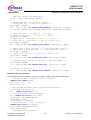
Example of Function Interfaces
This example reserves 5 GPIO pins, sets pin 1,2 and 5 to value 1 and gets the value of pin 4.
/* Initializes the corresponding driver instance */
VINETIC_GPIO_CONFIG ioCfg;
IFX_int32_t ctx, i, hd;
IFX_uint16_t val;
/* Get the device handle with a open from kernel space. */
/* Device 0 and channel 1*/
ctx = VINETIC_OpenKernel(0, 1);
/* reserve 5 pins and get the handle */
hd = VINETIC_GpioReserve(ctx, 0x1F);
ioCfg.nMode = GPIO_MODE_OUTPUT;
ioCfg.nGpio = 0x13;
ioCfg.callback = callback;
/* configure pins 1,2 and 5 as output */
VINETIC_GpioConfig(hd, &ioCfg);
ioCfg.nMode = GPIO_MODE_INPUT;
ioCfg.nGpio = 0x8;
/* configure pin 4 as input */
Preliminary User’s Manual
Programmer’s Reference
28
Revision 1.2, 2006-09-01
VINETIC®-CPE
Chip Set Family
CONFIDENTIAL
Description of the Device Driver Interfaces
VINETIC_GpioConfig(hd, &ioCfg);
/* set the value of pin 4 to 1 */
VINETIC_GpioSet(hd, 0x10, 0x10);
/* set the value of pins 1 and 2 to 1 */
VINETIC_GpioSet(hd, 0x03, 0x03);
/* get the value of pin 4 */
VINETIC_GpioGet(hd, &val, 0x08);
/* Release GPIO pin resource, can use also VINETIC_GpioRelease() */
VINETIC_ReleaseKernel(hd);
Preliminary User’s Manual
Programmer’s Reference
29
Revision 1.2, 2006-09-01
VINETIC®-CPE
Chip Set Family
CONFIDENTIAL
5
Device Driver Interfaces Reference
Device Driver Interfaces Reference
This section describes device specific interfaces, also called device driver interfaces.
5.1
ioctl Interfaces
This chapter describes all device driver interfaces. The ioctl commands are explained by mentioning the return
values for each function. The organization is as follows:
Table 5
Device Driver Interface Overview
Name
Description
Basic Interface
Basic Interface
Driver Initialization
Interface
Driver Initialization Interface
GPIO Interface
ioctl interface for GPIO/IO pin handling.
5.1.1
Basic Interface
Basic VINETIC® Access routines as command read and write and initialization.
Table 6
IO-control Overview of Basic Interface
Name
Description
FIO_VINETIC_VERS
Read relevant version information.
FIO_VINETIC_LASTERR
Get the last occurred error.
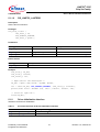
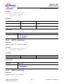
5.1.1.1
FIO_VINETIC_VERS
Description
Provide Vinetic driver versions information.
Prototype
IFX_void_t ioctl (
IFX_int32_t fd,
FIO_VINETIC_VERS,
IFX_int32_t param );
Parameters
Data Type
Name
Description
IFX_int32_t
fd
File descriptor
IFX_int32_t
FIO_VINETIC_VERS
I/O control identifier for this operation
IFX_int32_t
param
The parameter points to a
VINETIC_IO_VERSION structure.
Return Values
Data Type
Description
IFX_void_t
No return value
Preliminary User’s Manual
Programmer’s Reference
30
Revision 1.2, 2006-09-01
VINETIC®-CPE
Chip Set Family
CONFIDENTIAL
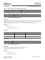
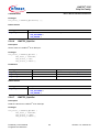
5.1.1.2
Device Driver Interfaces Reference
FIO_VINETIC_LASTERR
Description
Get the last occurred error.
Prototype
IFX_void_t ioctl (
IFX_int32_t fd,
FIO_VINETIC_LASTERR,
IFX_int32_t param );
Parameters
Data Type
Name
Description
IFX_int32_t
fd
File descriptor
IFX_int32_t
FIO_VINETIC_LASTERR
I/O control identifier for this operation
IFX_int32_t
param
The error codes are enumerated in DEV_ERR.
Return Values
Data Type
Description
IFX_void_t
No return value
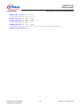
Example
IFX_int32_t fd_dev;
IFX_int32_t lasterr;
IFX_return_t ret;
/* Open control file descriptor */
fd_dev = open("/dev/vin10", O_RDWR, 0x644);
ret = ioctl(fd_dev, FIO_VINETIC_LASTERR, (IFX_int32_t) &lasterr);
printf("Last error = 0x%08x (%d), %d\n", lasterr, lasterr, ret);
/* Close all open fds */
close(fd_dev);
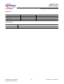
5.1.2
Driver Initialization Interface
Interfaces for the driver Initialization.
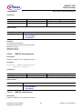
Table 7
IO-control Overview of Driver Initialization Interface
Name
Description
FIO_VINETIC_BASICDEV_INIT
Initialize VINETIC® device driver for the selected device.
FIO_VINETIC_DEV_RESET
Reset VINETIC® Device driver internal structure for the selected device.
Preliminary User’s Manual
Programmer’s Reference
31
Revision 1.2, 2006-09-01
VINETIC®-CPE
Chip Set Family
CONFIDENTIAL
Table 8
Device Driver Interfaces Reference
Structure Reference of Driver Initialization Interface
Name
Description
VINETIC_IO_INIT
Structure used for device initialization
Table 9
Enumerator Overview of Driver Initialization Interface
Name
Description
VIN_ACCESS
VINETIC® Access Modes.
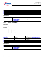
5.1.2.1
FIO_VINETIC_BASICDEV_INIT
Description
As the driver doesn’t support board dependent implementations anymore, this interface is to call at very first to
initialize the VINETIC® driver with the chip parameters passed the pointer to the structure
VINETIC_BasicDeviceInit_t. No chip access will be done until this basic initialization is successful.
Prototype
IFX_void_t ioctl (
IFX_int32_t fd,
FIO_VINETIC_BASICDEV_INIT,
IFX_int32_t param );
Parameters
Data Type
Name
Description
IFX_int32_t
fd
File descriptor
IFX_int32_t
FIO_VINETIC_BASICDEV_IN I/O control identifier for this operation
IT
IFX_int32_t
param
Use structure VINETIC_BasicDeviceInit_t
Return Values
Data Type
Description
IFX_void_t
No return value
5.1.2.2
FIO_VINETIC_DEV_RESET
Description
Reset VINETIC® Device driver internal structure for the selected device.
Attention: This interface does not issue a device reset!
Prototype
IFX_void_t ioctl (
IFX_int32_t fd,
FIO_VINETIC_DEV_RESET,
IFX_int32_t param );
Preliminary User’s Manual
Programmer’s Reference
32
Revision 1.2, 2006-09-01
VINETIC®-CPE
Chip Set Family
CONFIDENTIAL
Device Driver Interfaces Reference
Parameters
Data Type
Name
Description
IFX_int32_t
fd
File descriptor
IFX_int32_t
FIO_VINETIC_DEV_RESET
I/O control identifier for this operation
IFX_int32_t
param
Parameter not required.
Return Values
Data Type
Description
IFX_void_t
No return value
Preliminary User’s Manual
Programmer’s Reference
33
Revision 1.2, 2006-09-01
VINETIC®-CPE
Chip Set Family
CONFIDENTIAL
5.1.3
Device Driver Interfaces Reference
GPIO Interface
Control the device and channel specific IO pins.
Table 10
IO-control Overview of GPIO Interface
Name
Description
FIO_VINETIC_GPIO_CONFIG
Configure GPIO pins.
FIO_VINETIC_GPIO_GET
Get GPIO pin values.
FIO_VINETIC_GPIO_RELEASE
Release GPIO pin.
FIO_VINETIC_GPIO_RESERVE
Reserve GPIO pins for use.
FIO_VINETIC_GPIO_SET
Set GPIO pin values.
Table 11
Structure Overview of GPIO Interface
Name
Description
VINETIC_GPIO_CONFIG
GPIO Configuration Structure.
VINETIC_IO_GPIO_CONTROL
GPIO Control Structure.
5.1.3.1
FIO_VINETIC_GPIO_RESERVE
Description
Reserve GPIO pins.
Prototype
IFX_void_t ioctl (
IFX_int32_t fd,
FIO_VINETIC_GPIO_RESERVE,
IFX_int32_t param );
Parameters
Data Type
Name
Description
IFX_int32_t
fd
File descriptor
IFX_int32_t
FIO_VINETIC_GPIO_RESER I/O control identifier for this operation
VE
IFX_int32_t
param
Use structure VINETIC_IO_GPIO_CONTROL.
Return Values
Data Type
Description
IFX_void_t
No return value
5.1.3.2
FIO_VINETIC_GPIO_CONFIG
Description
Configure GPIO pins.
Preliminary User’s Manual
Programmer’s Reference
34
Revision 1.2, 2006-09-01
VINETIC®-CPE
Chip Set Family
CONFIDENTIAL
Device Driver Interfaces Reference
Prototype
IFX_void_t ioctl (
IFX_int32_t fd,
FIO_VINETIC_GPIO_CONFIG,
IFX_int32_t param );
Parameters
Data Type
Name
Description
IFX_int32_t
fd
File descriptor
IFX_int32_t
FIO_VINETIC_GPIO_CONFI
G
I/O control identifier for this operation
IFX_int32_t
param
Use structure VINETIC_IO_GPIO_CONTROL.
Return Values
Data Type
Description
IFX_void_t
No return value
5.1.3.3
FIO_VINETIC_GPIO_SET
Description
Set GPIO pin values.
Prototype
IFX_void_t ioctl (
IFX_int32_t fd,
FIO_VINETIC_GPIO_SET,
IFX_int32_t param );
Parameters
Data Type
Name
Description
IFX_int32_t
fd
File descriptor
IFX_int32_t
FIO_VINETIC_GPIO_SET
I/O control identifier for this operation
IFX_int32_t
param
Use structure VINETIC_IO_GPIO_CONTROL.
Return Values
Data Type
Description
IFX_void_t
No return value
5.1.3.4
FIO_VINETIC_GPIO_GET
Description
Get GPIO pin values.
Preliminary User’s Manual
Programmer’s Reference
35
Revision 1.2, 2006-09-01
VINETIC®-CPE
Chip Set Family
CONFIDENTIAL
Device Driver Interfaces Reference
Prototype
IFX_void_t ioctl (
IFX_int32_t fd,
FIO_VINETIC_GPIO_GET,
IFX_int32_t param );
Parameters
Data Type
Name
Description
IFX_int32_t
fd
File descriptor
IFX_int32_t
FIO_VINETIC_GPIO_GET
I/O control identifier for this operation
IFX_int32_t
param
Use structure VINETIC_IO_GPIO_CONTROL.
Return Values
Data Type
Description
IFX_void_t
No return value
5.1.3.5
FIO_VINETIC_GPIO_RELEASE
Description
Release GPIO.
Prototype
IFX_void_t ioctl (
IFX_int32_t fd,
FIO_VINETIC_GPIO_RELEASE,
IFX_int32_t param );
Parameters
Data Type
Name
Description
IFX_int32_t
fd
File descriptor
IFX_int32_t
FIO_VINETIC_GPIO_RELEA
SE
I/O control identifier for this operation
IFX_int32_t
param
Use structure VINETIC_IO_GPIO_CONTROL.
Return Values
Data Type
Description
IFX_void_t
No return value
5.2
Driver Function Interfaces
Device driver function interfaces.
Preliminary User’s Manual
Programmer’s Reference
36
Revision 1.2, 2006-09-01
VINETIC®-CPE
Chip Set Family
CONFIDENTIAL
Table 12
Device Driver Interfaces Reference
Function Overview of Driver Kernel Interface
Name
Description
VINETIC_OpenKernel
Open the device from Kernel mode.
VINETIC_ReleaseKernel
Release a VINETIC® IO or GPIO pin resource.
VINETIC_GpioReserve
Reserve a VINETIC® IO or GPIO pin resource.
VINETIC_GpioRelease
Release a VINETIC® IO or GPIO pin resource.
VINETIC_GpioConfig
Configure a VINETIC® IO or GPIO pin.
VINETIC_GpioSet
Set the value of a VINETIC® IO or GPIO pin.
VINETIC_GpioGet
Read the value from a VINETIC® IO or GPIO pin.
VINETIC_GpioIntMask
Set the interrupt enable mask.
Table 13
Enumerator Overview of Driver Kernel Interface
Name
Description
VINETIC_GPIO_MODE
GPIO pin configuration modes.
5.3
Type Definition Reference
This chapter contains the reference of data types and structures of all modules.
5.3.1
Basic Type Definitions
This section describes the basic type definitions such as:
•
•
•
•
•
•
•
•
•
•
•
•
IFX_return_t
IFX_boolean_t
IFX_uint8_t
IFX_int8_t
IFX_uint32_t
IFX_int32_t
IFX_uint16_t
IFX_int16_t
IFX_char_t
IFX_void_t
IFX_float_t
IFX_operation_t
5.3.1.1
IFX_return_t
Description
All the APIs return a Success or a Failure based on their execution Status. The return code is set to IFX_ERROR
only if an error occurs, otherwise its value is IFX_SUCCESS.
Prototype
typedef enum
{
IFX_ERROR = -1,
IFX_SUCCESS = 0
} IFX_return_t;
Preliminary User’s Manual
Programmer’s Reference
37
Revision 1.2, 2006-09-01
VINETIC®-CPE
Chip Set Family
CONFIDENTIAL
Device Driver Interfaces Reference
Parameters
Name
Value
Description
IFX_ERROR
-1D
Operation failed.
IFX_SUCCESS
0D
Operation was successful.
Name
Value
Description
IFX_FALSE
0D
False.
IFX_TRUE
1D
True.
5.3.1.2
IFX_boolean_t
Description
Definition for true and false.
Prototype
typedef enum
{
IFX_FALSE = 0,
IFX_TRUE = 1
} IFX_boolean_t;
Parameters
5.3.1.3
IFX_uint8_t
Prototype
typedef unsigned char IFX_uint8_t;
Parameters
Data Type
Name
Description
unsigned char
IFX_uint8_t
This is the unsigned char 8-bit datatype.
5.3.1.4
IFX_int8_t
Prototype
typedef char IFX_int8_t;
Parameters
Data Type
Name
Description
char
IFX_int8_t
This is the char 8-bit datatype.
Preliminary User’s Manual
Programmer’s Reference
38
Revision 1.2, 2006-09-01
VINETIC®-CPE
Chip Set Family
CONFIDENTIAL
5.3.1.5
Device Driver Interfaces Reference
IFX_uint32_t
Prototype
typedef unsigned int IFX_uint32_t;
Parameters
Data Type
Name
Description
unsigned int
IFX_uint32_t
This is the unsigned int 32-bit datatype.
5.3.1.6
IFX_int32_t
Prototype
typedef int IFX_int32_t;
Parameters
Data Type
Name
Description
int
IFX_int32_t
This is the int 32-bit datatype.
5.3.1.7
IFX_uint16_t
Prototype
typedef unsigned short IFX_uint16_t;
Parameters
Data Type
Name
Description
unsigned short
IFX_uint16_t
This is the unsigned short int 16-bit datatype.
5.3.1.8
IFX_int16_t
Prototype
typedef short IFX_int16_t;
Parameters
Data Type
Name
Description
short
IFX_int16_t
This is the short int 16-bit datatype.
5.3.1.9
IFX_char_t
Prototype
typedef char IFX_char_t;
Preliminary User’s Manual
Programmer’s Reference
39
Revision 1.2, 2006-09-01
VINETIC®-CPE
Chip Set Family
CONFIDENTIAL
Device Driver Interfaces Reference
Parameters
Data Type
Name
Description
char
IFX_char_t
This is the char 8-bit datatype.
5.3.1.10
IFX_void_t
Prototype
typedef void IFX_void_t;
Parameters
Data Type
Name
Description
void
IFX_void_t
This is a void datatype.
5.3.1.11
IFX_float_t
Prototype
typedef float IFX_float_t;
Parameters
Data Type
Name
Description
float
IFX_float_t
This is a float datatype.
5.3.1.12
IFX_operation_t
Description
Definition of enable and disable operation.
Prototype
typedef enum
{
IFX_DISABLE = 0,
IFX_ENABLE = 1
} IFX_operation_t;
Parameters
Name
Value
Description
IFX_DISABLE
0D
Disable.
IFX_ENABLE
1D
Enable.
Preliminary User’s Manual
Programmer’s Reference
40
Revision 1.2, 2006-09-01
VINETIC®-CPE
Chip Set Family
CONFIDENTIAL
5.3.1.13
Device Driver Interfaces Reference
IFX_vuint8_t
Description
This is the volatile unsigned 8-bit datatype.
Prototype
typedef volatile IFX_uint8_t IFX_vuint8_t;
Parameters
Data Type
Name
Description
volatile IFX_uint8_t
IFX_vuint8_t
This is the volatile unsigned 8-bit datatype.
5.3.1.14
IFX_vint8_t
Description
This is the volatile signed 8-bit datatype.
Prototype
typedef volatile IFX_int8_t IFX_vint8_t;
Parameters
Data Type
Name
Description
volatile IFX_int8_t
IFX_vint8_t
This is the volatile signed 8-bit datatype.
5.3.1.15
IFX_vuint16_t
Description
This is the volatile unsigned 16-bit datatype.
Prototype
typedef volatile IFX_uint16_t IFX_vuint16_t;
Parameters
Data Type
Name
Description
volatile
IFX_uint16_t
IFX_vuint16_t
This is the volatile unsigned 16-bit datatype.
5.3.1.16
IFX_vint16_t
Description
This is the volatile signed 16-bit datatype.
Preliminary User’s Manual
Programmer’s Reference
41
Revision 1.2, 2006-09-01
VINETIC®-CPE
Chip Set Family
CONFIDENTIAL
Device Driver Interfaces Reference
Prototype
typedef volatile IFX_int16_t IFX_vint16_t;
Parameters
Data Type
Name
Description
volatile IFX_int16_t
IFX_vint16_t
This is the volatile signed 16-bit datatype.
5.3.1.17
IFX_vuint32_t
Description
This is the volatile unsigned 32-bit datatype.
Prototype
typedef volatile IFX_uint32_t IFX_vuint32_t;
Parameters
Data Type
Name
Description
volatile
IFX_uint32_t
IFX_vuint32_t
This is the volatile unsigned 32-bit datatype.
5.3.1.18
IFX_vint32_t
Description
This is the volatile signed 32-bit datatype.
Prototype
typedef volatile IFX_int32_t IFX_vint32_t;
Parameters
Data Type
Name
Description
volatile IFX_int32_t
IFX_vint32_t
This is the volatile signed 32-bit datatype.
5.3.1.19
IFX_vfloat_t
Description
This is the volatile float datatype.
Prototype
typedef volatile IFX_float_t IFX_vfloat_t;
Preliminary User’s Manual
Programmer’s Reference
42
Revision 1.2, 2006-09-01
VINETIC®-CPE
Chip Set Family
CONFIDENTIAL
Device Driver Interfaces Reference
Parameters
Data Type
Name
Description
volatile IFX_float_t
IFX_vfloat_t
This is the volatile float datatype.
5.3.2
IO-control Reference
This chapter contains the IO-control reference.
Table 14
IO-control Overview of Device Driver Interfaces
Name
Description
FIO_VINETIC_DRV_CTRL
Driver configuration.
FIO_VINETIC_VERS
Read relevant version information.
FIO_VINETIC_LASTERR
Get the last occurred error.
FIO_VINETIC_DEV_GPIO_CFG
Configure device GPIO pins 0.
FIO_VINETIC_DEV_GPIO_SET
Set GPIO pins values.
FIO_VINETIC_GPIO_RESERVE
Reserve GPIO pins for use.
FIO_VINETIC_GPIO_CONFIG
Configure GPIO pins.
FIO_VINETIC_GPIO_SET
Set GPIO pin values.
FIO_VINETIC_GPIO_GET
Get GPIO pin values.
FIO_VINETIC_GPIO_RELEASE
Release GPIO.
FIO_VINETIC_BASICDEV_INIT
Initialize VINETIC® Device driver information for the selected
device.
FIO_VINETIC_DEV_RESET
Reset VINETIC® Device driver internal structure for the selected
device.
5.3.3
Constant Reference
This chapter contains the constant reference.
Table 15
Constant Overview of Device Driver Interfaces
Name
Description
MAX_CMD_WORD
Maximal Command/Data Words.
MAX_PACKET_WORD
Maximal Packet Words.
VINETIC_CH_NR
VINETIC® maximum channel number.
VINETIC_ANA_CH_NR
VINETIC® maximum analog channel number.
NO_BCONF
Flag for VINETIC_IO_INIT to avoid no board configuration.
NO_EDSP_START
Flag for VINETIC_IO_INIT to avoid EDSP start.
NO_FW_DWLD
Flag for VINETIC_IO_INIT to avoid firmware download.
VIN_BUF_HDR1_CH
Packet Header Masks for channel number.
VIN_BUF_HDR1_DEV
Packet Header Masks for device number.
VIN_BUF_HDR2_LEN
Packet Header Masks for payload length in words.
VIN_BUF_HDR2_ODD
Packet Header Masks for odd bit (set if the last byte in the last word is
padding).
Preliminary User’s Manual
Programmer’s Reference
43
Revision 1.2, 2006-09-01
VINETIC®-CPE
Chip Set Family
CONFIDENTIAL
Table 16
Device Driver Interfaces Reference
Constant Reference for Device Driver Interfaces
Name and Description
Value
MAX_CMD_WORD
Maximal Command/Data Words.
31D
MAX_PACKET_WORD
Maximal Packet Words.
255D
VINETIC_CH_NR
VINETIC® maximum channel number.
8D
VINETIC_ANA_CH_NR
VINETIC® maximum analog channel number.
4D
NO_BCONF
Flag for VINETIC_IO_INIT to avoid no board configuration.
1H
NO_EDSP_START
Flag for VINETIC_IO_INIT to avoid EDSP start.
2H
NO_FW_DWLD
Flag for VINETIC_IO_INIT to avoid firmware download.
100H
VIN_BUF_HDR1_CH
Packet Header Masks for channel number.
3H
VIN_BUF_HDR1_DEV
Packet Header Masks for device number.
FCH
VIN_BUF_HDR2_LEN
Packet Header Masks for payload length in words.
FFH
VIN_BUF_HDR2_ODD
Packet Header Masks for odd bit (set if the last byte in the last word is padding).
2000H
5.3.4
Structure Reference
This chapter contains the Structure reference.
Table 17
Structure Overview of Device Driver Interfaces
Name
Description
VINETIC_BasicDeviceInit_t
VINETIC® Basic Device Initialization structure.
VINETIC_GPIO_CONFIG
GPIO Configuration Structure.
VINETIC_IO_GPIO_CONTROL
GPIO Control Structure.
VINETIC_IO_INIT
Structure used for device initialization
VINETIC_IO_VERSION
Version IO structure.
5.3.4.1
VINETIC_BasicDeviceInit_t
Description
VINETIC® Basic Device Initialization structure.
Prototype
typedef struct
{
VIN_ACCESS AccessMode;
Preliminary User’s Manual
Programmer’s Reference
44
Revision 1.2, 2006-09-01
VINETIC®-CPE
Chip Set Family
CONFIDENTIAL
Device Driver Interfaces Reference
IFX_uint32_t nBaseAddress;
IFX_int32_t nIrqNum;
} VINETIC_BasicDeviceInit_t;
Parameters
Data Type
Name
Description
VIN_ACCESS
AccessMode
Access mode for VINETIC® device.
IFX_uint32_t
nBaseAddress
VINETIC® physical base address.
IFX_int32_t
nIrqNum
VINETIC® device irq number, as defined by the
target OS.
5.3.4.2
VINETIC_GPIO_CONFIG
Description
GPIO Configuration structure.
Prototype
typedef struct
{
IFX_uint16_t nGpio;
IFX_uint32_t nMode;
IFX_void_t (*callback)(int nDev, int nCh, unsigned short nEvt);
} VINETIC_GPIO_CONFIG_t;
Parameters
Data Type
Name
Description
IFX_uint16_t
nGpio
Mask for GPIO resources.
IFX_uint32_t
nMode
GPIO mode (input, output, interrupt).
IFX_void_t
(*callback)(int nDev, int nCh,
unsigned short nEvt)
Callback for interrupt routine.
5.3.4.3
VINETIC_IO_GPIO_CONTROL
Description
GPIO Control Structure.
Prototype
typedef struct
{
IFX_int32_t ioHandle;
IFX_uint16_t nGpio;
IFX_uint16_t nMask;
} VINETIC_IO_GPIO_CONTROL_t;
Preliminary User’s Manual
Programmer’s Reference
45
Revision 1.2, 2006-09-01
VINETIC®-CPE
Chip Set Family
CONFIDENTIAL
Device Driver Interfaces Reference
Parameters
Data Type
Name
Description
IFX_int32_t
ioHandle
GPIO handle.
IFX_uint16_t
nGpio
GPIO resource mask. Least significant bit
corresponds to pin 0.
IFX_uint16_t
nMask
Mask for current command.
5.3.4.4
VINETIC_IO_INIT
Description
Structure used for device initialization.
Prototype
typedef struct
{
IFX_uint8_t* pPRAMfw;
IFX_uint32_t pram_size;
IFX_uint8_t* pDRAMfw;
IFX_uint32_t dram_size;
IFX_uint8_t* pPHIfw;
IFX_uint32_t phi_size;
IFX_uint8_t* pCram;
IFX_uint32_t cram_size;
IFX_uint8_t* pBBDbuf;
IFX_uint32_t bbd_size;
IFX_uint32_t nFlags;
IFX_uint16_t nPramCRC;
IFX_uint16_t nDramCRC;
IFX_uint16_t nPhiCrc;
IFX_uint16_t nDcCrc;
IFX_uint16_t nAcCrc;
IFX_uint16_t nCramCrc;
} VINETIC_IO_INIT_t;
Parameters
Data Type
Name
Description
IFX_uint8_t*
pPRAMfw
Firmware PRAM pointer or NULL if not needed.
IFX_uint32_t
pram_size
Size of PRAM firmware in bytes
IFX_uint8_t*
pDRAMfw
Firmware DRAM pointer or NULL if not needed.
IFX_uint32_t
dram_size
Size of DRAM firmware in bytes
IFX_uint8_t*
pPHIfw
Pointer optional PHI program
IFX_uint32_t
phi_size
Size of PHI program in bytes
IFX_uint8_t*
pCram
Pointer to CRAM
IFX_uint32_t
cram_size
Size of CRAM coefficients in bytes
IFX_uint8_t*
pBBDbuf
Pointer to BBD format data
Preliminary User’s Manual
Programmer’s Reference
46
Revision 1.2, 2006-09-01
VINETIC®-CPE
Chip Set Family
CONFIDENTIAL
Device Driver Interfaces Reference
Data Type
Name
Description
IFX_uint32_t
bbd_size
Size of BBD buffer
IFX_uint32_t
nFlags
Flags for initialization.
Most of the flags are only used from experts to
modify the default initialization.
• NO_BCONF: no board configuration will be
done. VINETIC® must be properly got out of
reset
• NO_PHI_DWLD: no PHI download will be
done, a properly PHI download before is
assumed
• NO_EDSP_START: no EDPS start is done.
The VVINETIC® will not work until that
command is given
• NO_CRAM_DWLD: no CRAM coefficients
are downloaded. The default ROM
coefficients are used
• FW_AUTODWLD: firmware auto download
• NO_AC_DWLD: avoid AC download in
case of V1.4, no effect with any other chip
version
• DC_DWLD: do a DC download in case of
V1.4
• NO_FW_DWLD: no firmware download
IFX_uint16_t
nPramCRC
Return values of PRAM CRC after firmware
download
IFX_uint16_t
nDramCRC
Return values of DRAM CRC after firmware
download
IFX_uint16_t
nPhiCrc
Return values of PHI checksum after PHI
program download.
0 if not done
IFX_uint16_t
nDcCrc
Return values of DCCTL checksum after
DCCTL download.
0 if not done
IFX_uint16_t
nAcCrc
Return values of AC control after ALM-DSP
download.
0 if not done
IFX_uint16_t
nCramCrc
Return values of CRAM checksum after CRAM
download.
0 if not done
5.3.4.5
VINETIC_IO_VERSION
Description
Version IO structure.
Prototype
typedef struct
{
Preliminary User’s Manual
Programmer’s Reference
47
Revision 1.2, 2006-09-01
VINETIC®-CPE
Chip Set Family
CONFIDENTIAL
Device Driver Interfaces Reference
IFX_uint8_t nType;
IFX_uint8_t nChannel;
IFX_uint16_t nChip;
IFX_uint32_t nTapiVers;
IFX_uint32_t nDrvVers;
IFX_uint16_t nEdspVers;
IFX_uint16_t nEdspIntern;
} VINETIC_IO_VERSION_t;
Parameters
Data Type
Name
Description
IFX_uint8_t
nType
Chip type
IFX_uint8_t
nChannel
Number of supported analog channels
IFX_uint16_t
nChip
Chip revision.
IFX_uint32_t
nTapiVers
Included TAPI version
IFX_uint32_t
nDrvVers
Driver version.
IFX_uint16_t
nEdspVers
EDSP major version.
IFX_uint16_t
nEdspIntern
EDSP version step.
5.3.5
Enumerator Reference
This chapter contains the Enumerator reference.
Table 18
Enumerator Overview of Non TAPI Interfaces
Name
Description
VINETIC_IO_CHIP_REVISION
VINETIC® Chip Revision.
VINETIC_IO_CHIP_MAJOR_REVISION
VINETIC® Chip Major Revision.
VINETIC_IO_CHIP_TYPE
VINETIC® chip types, depending on register Revision and
firmware download.
VIN_ACCESS
VINETIC® Access Modes.
VINETIC_GPIO_MODE
GPIO pin configuration modes.
DEV_ERR
Driver error codes.
5.3.5.1
VINETIC_IO_CHIP_REVISION
Description
VINETIC® Chip Revision.
Prototype
typedef enum
{
VINETIC_V13
VINETIC_V14
VINETIC_V15
VINETIC_V16
VINETIC_V21
VINETIC_V22
=
=
=
=
=
=
Preliminary User’s Manual
Programmer’s Reference
0x42,
0x84,
0x85,
0x86,
0x90,
0xA0,
48
Revision 1.2, 2006-09-01
VINETIC®-CPE
Chip Set Family
CONFIDENTIAL
Device Driver Interfaces Reference
VINETIC_V21_S = 0xB0,
VINETIC_2CPE_V21 = 0x60,
VINETIC_2CPE_V22 = 0x66,
VINETIC_2CPE_AMR = 0x68
} VINETIC_IO_CHIP_REVISION_t;
Parameters
Name
Value
Description
VINETIC_V13
42H
Version V1.3.
VINETIC_V14
84H
Version V1.4.
VINETIC_V15
85H
Version V1.5, no longer available.
VINETIC_V16
86H
Version V1.6, internal version.
VINETIC_V21
90H
Version V2.1, VINETIC®-4M.
VINETIC_V22
A0H
Version V2.2, VINETIC®-4M/-4C.
VINETIC_V21_S
B0H
Version V2.1 of VINETIC®-4S.
VINETIC_2CPE_V21
60H
Version V2.1 of VINETIC®-2CPE/-1CPE.
VINETIC_2CPE_V22
66H
Version V2.2 of VINETIC®-2CPE/-1CPE.
VINETIC_2CPE_AMR
68H
AMR of VINETIC®-2CPE/-1CPE.
5.3.5.2
VINETIC_IO_CHIP_MAJOR_REVISION
Description
VINETIC® Chip Major Revision.
Prototype
typedef enum
{
VINETIC_V1x = 1,
VINETIC_V2x = 2
} VINETIC_IO_CHIP_MAJOR_REVISION_t;
Parameters
Name
Value
Description
VINETIC_V1x
1D
Version V1.x.
VINETIC_V2x
2D
Version V2.x.
5.3.5.3
VINETIC_IO_CHIP_TYPE
Description
VINETIC® chip types, depending on register REVISION and firmware download.
Prototype
typedef enum
{
Preliminary User’s Manual
Programmer’s Reference
49
Revision 1.2, 2006-09-01
VINETIC®-CPE
Chip Set Family
CONFIDENTIAL
Device Driver Interfaces Reference
VINETIC_TYPE_S = 0x0,
VINETIC_TYPE_M = 0x1,
VINETIC_TYPE_VIP = 0x2,
VINETIC_TYPE_C = 0x4,
VINETIC_TYPE_CPE = 0x5
} VINETIC_IO_CHIP_TYPE_t;
Parameters
Name
Value
Description
VINETIC_TYPE_S
0H
Chip type S
VINETIC_TYPE_M
1H
Chip type M
VINETIC_TYPE_VIP
2H
Chip type VIP
VINETIC_TYPE_C
4H
Chip type C
VINETIC_TYPE_CPE
5H
Chip type CPE
5.3.5.4
VIN_ACCESS
Description
VINETIC® Access Modes.
Only available in VINETIC®-2CPE/-1CPE Version 2.1: 8-bit INTEL Mux, 8-bit INTEL Demux, 8-bit Motorola, and
SCI.
Prototype
typedef enum
{
VIN_ACCESS_SPI = 0,
VIN_ACCESS_SCI = 1,
VIN_ACCESS_PAR_16BIT = 2,
VIN_ACCESS_PAR_8BIT = 3,
VIN_ACCESS_PARINTEL_DMUX16 = 4,
VIN_ACCESS_PARINTEL_MUX16 = 5,
VIN_ACCESS_PARINTEL_MUX8 = 6,
VIN_ACCESS_PARINTEL_DMUX8 = 7,
VIN_ACCESS_PARINTEL_DMUX8_BE = 8,
VIN_ACCESS_PARINTEL_DMUX8_LE = 9,
VIN_ACCESS_PAR_8BIT_V2 = 10
} VIN_ACCESS_t;
Parameters
Name
Value
Description
VIN_ACCESS_SPI
0D
Host interface used, SPI.
VIN_ACCESS_SCI
1D
Host interface used, SCI.
VIN_ACCESS_PAR_16BIT
2D
Host interface used, parallel Motorola 16-bit.
VIN_ACCESS_PAR_8BIT
3D
Host interface used, parallel Motorola 8-bit.
Preliminary User’s Manual
Programmer’s Reference
50
Revision 1.2, 2006-09-01
VINETIC®-CPE
Chip Set Family
CONFIDENTIAL
Device Driver Interfaces Reference
Name
Value
Description
VIN_ACCESS_PARINTEL_DMUX16
4D
Host interface used, parallel Intel 16-bit
demultiplexed.
VIN_ACCESS_PARINTEL_MUX16
5D
Host interface used, parallel Intel 16-bit
multiplexed.
VIN_ACCESS_PARINTEL_MUX8
6D
Host interface used, parallel Intel 8-bit
multiplexed.
VIN_ACCESS_PARINTEL_DMUX8
7D
Host interface used, parallel Intel 8-bit
demultiplexed.
VIN_ACCESS_PARINTEL_DMUX8_BE
8D
Access parallel intel demux 8-bit big-endian.
Supported by V1 chip version.
This mode should not be used anymore.
VIN_ACCESS_PARINTEL_DMUX8_LE
9D
Access parallel intel demux 8-bit little-endian.
Supported by V2 chip version.
This mode should not be used anymore.
VIN_ACCESS_PAR_8BIT_V2
10D
Access parallel motorola 8-bit big-endian with
16-bit processor interface.
Supported by V2 chip version.
This mode should not be used anymore.
5.3.5.5
VINETIC_GPIO_MODE
Description
GPIO and IO pin configuration modes.
Prototype
typedef enum
{
GPIO_MODE_INPUT = 0x100,
GPIO_MODE_OUTPUT = 0x200,
GPIO_MODE_INT = 0x400,
GPIO_INT_RISING = 0x1000,
GPIO_INT_FALLING = 0x2000,
GPIO_INT_DUP_05 = 0x0000,
GPIO_INT_DUP_45 = 0x0001,
GPIO_INT_DUP_85 = 0x0002,
GPIO_INT_DUP_125 = 0x0003,
GPIO_INT_DUP_165 = 0x0004,
GPIO_INT_DUP_205 = 0x0005,
GPIO_INT_DUP_245 = 0x0006,
GPIO_INT_DUP_285 = 0x0007,
GPIO_INT_DUP_325 = 0x0008,
GPIO_INT_DUP_365 = 0x0009,
GPIO_INT_DUP_405 = 0x000A,
GPIO_INT_DUP_445 = 0x000B,
GPIO_INT_DUP_485 = 0x000C,
GPIO_INT_DUP_525 = 0x000D,
GPIO_INT_DUP_565 = 0x000E,
GPIO_INT_DUP_605 = 0x000F
Preliminary User’s Manual
Programmer’s Reference
51
Revision 1.2, 2006-09-01
VINETIC®-CPE
Chip Set Family
CONFIDENTIAL
Device Driver Interfaces Reference
} VINETIC_GPIO_MODE_t;
Parameters
Name
Value
Description
GPIO_MODE_INPUT
100H
GPIO pin set as input.
GPIO_MODE_OUTPUT
200H
GPIO pin set as output.
GPIO_MODE_INT
400H
GPIO pin set as interrupt.
GPIO_INT_RISING
1000H
GPIO pin set as rising-edge interrupt.
GPIO_INT_FALLING
2000H
GPIO pin set as falling-edge interrupt.
GPIO_INT_DUP_05
0000H
Reserved.
GPIO_INT_DUP_45
0001H
Reserved.
GPIO_INT_DUP_85
0002H
Reserved.
GPIO_INT_DUP_125
0003H
Reserved.
GPIO_INT_DUP_165
0004H
Reserved.
GPIO_INT_DUP_205
0005H
Reserved.
GPIO_INT_DUP_245
0006H
Reserved.
GPIO_INT_DUP_285
0007H
Reserved.
GPIO_INT_DUP_325
0008H
Reserved.
GPIO_INT_DUP_365
0009H
Reserved.
GPIO_INT_DUP_405
000AH
Reserved.
GPIO_INT_DUP_445
000BH
Reserved.
GPIO_INT_DUP_485
000CH
Reserved.
GPIO_INT_DUP_525
000DH
Reserved.
GPIO_INT_DUP_565
000EH
Reserved.
GPIO_INT_DUP_605
000FH
Reserved.
5.3.5.6
DEV_ERR
Description
Driver error codes
Prototype
typedef enum
{
ERR_OK = 0,
ERR_CERR = 0x01,
ERR_CIBX_OF = 0x2,
ERR_HOST = 0x3,
ERR_MIPS_OL = 0x4,
ERR_NO_COBX = 0x5,
ERR_NO_DATA = 0x6,
ERR_NO_FIBXMS = 0x7,
ERR_MORE_DATA = 0x8,
ERR_NO_MBXEMPTY = 0x9,
ERR_NO_DLRDY = 0xA,
Preliminary User’s Manual
Programmer’s Reference
52
Revision 1.2, 2006-09-01
VINETIC®-CPE
Chip Set Family
CONFIDENTIAL
Device Driver Interfaces Reference
ERR_WRONGDATA = 0xB,
ERR_OBXML_ZERO = 0xC,
ERR_TEST_FAIL = 0xD,
ERR_HW_ERR = 0xE,
ERR_PIBX_OF = 0xF,
ERR_FUNC_PARM = 0x10,
ERR_TO_CHSTATE = 0x11,
ERR_BUF_UN = 0x12,
ERR_NO_MEM = 0x13,
ERR_NOINIT = 0x14,
ERR_INTSTUCK = 0x15,
ERR_LT_ON = 0x16,
ERR_NOPHI = 0x17,
ERR_EDSP_FAIL = 0x18,
ERR_FWCRC_FAIL = 0x19,
ERR_NO_TAPI = 0x1A,
ERR_SPI = 0x1B,
ERR_INVALID = 0x1C,
ERR_GR909 = 0x1D,
ERR_ACCRC_FAIL = 0x1E,
ERR_NO_VERSION = 0x1F,
ERR_DCCRC_FAIL = 0x20,
ERR_UNKNOWN_VERSION = 0x21,
ERR_LT_LINE_IS_PDNH = 0x22,
ERR_LT_UNKNOWN_PARAM = 0x23,
ERR_CID_TRANSMIT = 0x24,
ERR_LT_TIMEOUT_LM_OK = 0x25,
ERR_LT_TIMEOUT_LM_RAMP_RDY = 0x26,
ERR_PRAM_FW = 0x27,
ERR_NOFW = 0x28,
ERR_PHICRC0 = 0x29,
ERR_ARCDWLD_FAIL = 0x2A,
ERR_ARCDWLD_BOOT = 0x2B,
ERR_FWINVALID = 0x2C,
ERR_NOFWVERS = 0x2D,
ERR_NOMAXCBX = 0x2E,
ERR_SIGMOD_NOTEN = 0x2F,
ERR_SIGCH_NOTEN = 0x30,
ERR_CODCONF_NOTVALID = 0x31,
ERR_LT_OPTRES_FAILED = 0x32,
ERR_NO_FREE_INPUT_SLOT = 0x33,
ERR_NOTSUPPORTED = 0x34,
ERR_NORESOURCE = 0x35,
ERR_WRONG_EVPT = 0x36,
ERR_CON_INVALID = 0x37,
ERR_HOSTREG_ACCESS = 0x38,
ERR_NOPKT_BUFF = 0x39,
ERR_COD_RUNNING = 0x3A,
ERR_TONE_PLAYING = 0x3B,
ERR_INVALID_TONERES = 0x3C,
ERR_INVALID_SIGSTATE = 0x3D,
Preliminary User’s Manual
Programmer’s Reference
53
Revision 1.2, 2006-09-01
VINETIC®-CPE
Chip Set Family
CONFIDENTIAL
Device Driver Interfaces Reference
ERR_INVALID_UTGSTATE = 0x3E,
ERR_CID_RUNNING = 0x3F,
ERR_UNKNOWN = 0x40,
ERR_WRONG_CHANNEL_MODE = 0x41,
ERR_DRVINIT_FAIL = 0x80,
ERR_DEV_ERR = 0x81
} DEV_ERR_t;
Parameters
Name
Value
Description
ERR_OK
0
0x0: no error
ERR_CERR
01H
Command error reported by VINETIC®, see last
command
ERR_CIBX_OF
2H
Command inbox overflow reported by VINETIC®
ERR_HOST
3H
Host error reported by VINETIC®
ERR_MIPS_OL
4H
MIPS overload.
ERR_NO_COBX
5H
No command data received event within time-out.
This error is obsolete, since the driver used a polling
mode
ERR_NO_DATA
6H
No command data received within time-out
ERR_NO_FIBXMS
7H
Not enough inbox space for writing command
ERR_MORE_DATA
8H
More data then expected in outbox
ERR_NO_MBXEMPTY
9H
Mailbox was not empty after time-out. This error
occurs while the driver tries to switch the mailbox
sizes before and after the firmware download. The
time-out is given in the constant
WAIT_MBX_EMPTY
ERR_NO_DLRDY
AH
Download ready event has not occurred
ERR_WRONGDATA
BH
Register read: expected values do not match
ERR_OBXML_ZERO
CH
OBXML is zero after COBX-DATA event.
This error is obsolete, since the driver is polling the
OBXML register, i.e. the COBX-DATA event is not
handled anymore in the interrupt routine.
ERR_TEST_FAIL
DH
Test chip access failed.
ERR_HW_ERR
EH
Internal EDSP hardware error reported by VINETIC®
in HWSR1:HW-ERR.
ERR_PIBX_OF
FH
Mailbox Overflow Error.
ERR_FUNC_PARM
10H
Invalid parameter in function call
ERR_TO_CHSTATE
11H
Time-out while waiting on channel status change
ERR_BUF_UN
12H
Buffer under run in evaluation down streaming
ERR_NO_MEM
13H
No memory by memory allocation
ERR_NOINIT
14H
Board previously not initialized
ERR_INTSTUCK
15H
Interrupts can not be cleared
ERR_LT_ON
16H
Line testing measurement is running
Preliminary User’s Manual
Programmer’s Reference
54
Revision 1.2, 2006-09-01
VINETIC®-CPE
Chip Set Family
CONFIDENTIAL
Device Driver Interfaces Reference
Name
Value
Description
ERR_NOPHI
17H
PHI patch was not successfully downloaded. The
problem was a chip access problem
ERR_EDSP_FAIL
18H
EDSP Failures.
ERR_FWCRC_FAIL
19H
CRC Fail while FW download.
ERR_NO_TAPI
1AH
TAPI not initialized.
ERR_SPI
1BH
Error while using SPI Interface.
ERR_INVALID
1CH
Inconsistent or invalid parameters were provided
ERR_GR909
1DH
No Data to copy to user space for GR909
measurement
ERR_ACCRC_FAIL
1EH
CRC Fail while ALM-DSP download for V1.4.
ERR_NO_VERSION
1FH
Couldn't read out chip version
ERR_DCCRC_FAIL
20H
CRC Fail in DCCTRL download.
ERR_UNKNOWN_VERSION
21H
Unknown chip version
ERR_LT_LINE_IS_PDNH
22H
Linetesting, line is in Power Down High Impedance,
measurement not possible.
ERR_LT_UNKNOWN_PARAM
23H
Linetesting, unknown Parameter.
ERR_CID_TRANSMIT
24H
Error while sending CID.
ERR_LT_TIMEOUT_LM_OK
25H
Linetesting, time-out waiting for LM_OK.
ERR_LT_TIMEOUT_LM_RAMP_RDY
26H
Linetesting, time-out waiting for RAMP_RDY
ERR_PRAM_FW
27H
Invalid pram fw length
ERR_NOFW
28H
No firmware specified and not included in driver
ERR_PHICRC0
29H
PHI CRC is zero.
ERR_ARCDWLD_FAIL
2AH
Embedded Controller download failed.
ERR_ARCDWLD_BOOT
2BH
Embedded Controller boot failed after download.
ERR_FWINVALID
2CH
Firmware binary is invalid.
ERR_NOFWVERS
2DH
Firmware version could not be read, no answer to
command.
ERR_NOMAXCBX
2EH
Maximize mailbox failed.
ERR_SIGMOD_NOTEN
2FH
Signaling module not enabled.
ERR_SIGCH_NOTEN
30H
Signaling channel not enabled.
ERR_CODCONF_NOTVALID
31H
Coder configuration not valid
ERR_LT_OPTRES_FAILED
32H
Linetesting, optimum result routine failed.
ERR_NO_FREE_INPUT_SLOT
33H
No free input found while connecting cod, sig and alm
modules.
ERR_NOTSUPPORTED
34H
Feature or combination not supported
ERR_NORESOURCE
35H
Resource not available
ERR_WRONG_EVPT
36H
Event payload type mismatch.
ERR_CON_INVALID
37H
Connection not valid on remove.
ERR_HOSTREG_ACCESS
38H
Host register access failure [2CPE].
ERR_NOPKT_BUFF
39H
No packet buffers available.
ERR_COD_RUNNING
3AH
At least one parameter is not possible to apply when
the coder is running. Event payload types cannot be
changed on the fly.
Preliminary User’s Manual
Programmer’s Reference
55
Revision 1.2, 2006-09-01
VINETIC®-CPE
Chip Set Family
CONFIDENTIAL
Device Driver Interfaces Reference
Name
Value
Description
ERR_TONE_PLAYING
3BH
Tone is already played out on this channel.
ERR_INVALID_TONERES
3CH
Tone resource is not capable playing out a certain
tone. This error should not occur -> internal
mismatch.
ERR_INVALID_SIGSTATE
3DH
Invalid state for switching off signaling modules.
Internal error.
ERR_INVALID_UTGSTATE
3EH
Invalid state for switching off signaling modules.
Internal error.
ERR_CID_RUNNING
3FH
Cid sending is ongoing in this channel.
ERR_UNKNOWN
40H
Some internal state occured, that could not be
handled. This error should never occur.
ERR_WRONG_CHANNEL_MODE
41H
Action not supported with this TAPI initialisation
mode.
ERR_DRVINIT_FAIL
80H
Driver initialization failed
ERR_DEV_ERR
81H
General access error, RDQ bit is always 1
5.3.6
Function Reference
This chapter contains the function reference.
Table 19
Function Overview of Non TAPI Interfaces
Name
Description
VINETIC_OpenKernel
Open the device from kernel mode.
VINETIC_ReleaseKernel
Release a VINETIC® IO or GPIO pin resource.
VINETIC_GpioReserve
Reserve a VINETIC® IO or GPIO pin resource.
VINETIC_GpioRelease
Release a VINETIC® IO or GPIO pin resource.
VINETIC_GpioConfig
Configure a VINETIC® IO or GPIO pin.
VINETIC_GpioSet
Set the value of a VINETIC® IO or GPIO pin.
VINETIC_GpioGet
Read the value from a VINETIC® IO or GPIO pin.
VINETIC_GpioIntMask
Set the interrupt enable mask.
5.3.6.1
VINETIC_OpenKernel
Description
Open the device from Kernel mode.
Prototype
IFX_int32_t VINETIC_OpenKernel (
IFX_int32_t nDev,
IFX_int32_t nCh );
Preliminary User’s Manual
Programmer’s Reference
56
Revision 1.2, 2006-09-01
VINETIC®-CPE
Chip Set Family
CONFIDENTIAL
Device Driver Interfaces Reference
Parameters
Data Type
Name
Description
IFX_int32_t
nDev
Index of the VINETIC® device
IFX_int32_t
nCh
Index of the VINETIC® channel (1 = channel
0...)
Return Values
Data Type
Description
IFX_int32_t
The return value can be either of the following:
• IFX_SUCCESS 0
• IFX_ERROR -1
Remarks
If not already done this will
allocate internal memory for each new device
allocate io memory
initialize the device
set up the interrupt
5.3.6.2
VINETIC_ReleaseKernel
Description
Release a VINETIC® IO or GPIO pin resource.
Prototype
IFX_int32_t VINETIC_ReleaseKernel (
IFX_int32_t nHandle );
Parameters
Data Type
Name
Description
IFX_int32_t
nHandle
Handle returned by VINETIC_GpioReserve
Return Values
Data Type
Description
IFX_int32_t
The return value can be either of the following:
• IFX_SUCCESS 0
• IFX_ERROR -1
5.3.6.3
VINETIC_GpioReserve
Description
Reserve a VINETIC® IO or GPIO pin resource.
Preliminary User’s Manual
Programmer’s Reference
57
Revision 1.2, 2006-09-01
VINETIC®-CPE
Chip Set Family
CONFIDENTIAL
Device Driver Interfaces Reference
Prototype
IFX_int32_t VINETIC_GpioReserve (
IFX_int32_t devHandle,
IFX_uint16_t nGpio );
Parameters
Data Type
Name
Description
IFX_int32_t
devHandle
Handle to either VINETIC® device or channel
structure
IFX_uint16_t
nGpio
Mask for GPIOs to reserve (0 = free, 1 =
reserve)
Return Values
Data Type
Description
IFX_int32_t
The return value can be either of the following:
• IFX_SUCCESS 0
• IFX_ERROR -1
5.3.6.4
VINETIC_GpioRelease
Description
Release a VINETIC® IO or GPIO pin resource.
Prototype
IFX_int32_t VINETIC_GpioRelease (
IFX_int32_t ioHandle );
Parameters
Data Type
Name
Description
IFX_int32_t
ioHandle
Handle returned by VINETIC_GpioReserve
Return Values
Data Type
Description
IFX_int32_t
The return value can be either of the following:
• IFX_SUCCESS 0
• IFX_ERROR -1
5.3.6.5
VINETIC_GpioConfig
Description
Configure a VINETIC® IO or GPIO pin.
Preliminary User’s Manual
Programmer’s Reference
58
Revision 1.2, 2006-09-01
VINETIC®-CPE
Chip Set Family
CONFIDENTIAL
Device Driver Interfaces Reference
Prototype
IFX_int32_t VINETIC_GpioConfig ( );
Return Values
Data Type
Description
IFX_int32_t
The return value can be either of the following:
• IFX_SUCCESS 0
• IFX_ERROR -1
5.3.6.6
VINETIC_GpioSet
Description
Set the value of a VINETIC® IO or GPIO pin.
Prototype
IFX_int32_t VINETIC_GpioSet (
IFX_int32_t ioHandle,
IFX_uint16_t nSet,
IFX_uint16_t nMask );
Parameters
Data Type
Name
Description
IFX_int32_t
ioHandle
Handle returned by VINETIC_GpioReserve
IFX_uint16_t
nSet
Values to store
IFX_uint16_t
nMask
Only bits set to '1' will be stored
Return Values
Data Type
Description
IFX_int32_t
The return value can be either of the following:
• IFX_SUCCESS 0
• IFX_ERROR -1
5.3.6.7
VINETIC_GpioGet
Description
Read the value from a VINETIC® IO or GPIO pin.
Prototype
IFX_int32_t VINETIC_GpioGet (
IFX_int32_t ioHandle,
IFX_uint16_t* nGet,
IFX_uint16_t nMask );
Preliminary User’s Manual
Programmer’s Reference
59
Revision 1.2, 2006-09-01
VINETIC®-CPE
Chip Set Family
CONFIDENTIAL
Device Driver Interfaces Reference
Parameters
Data Type
Name
Description
IFX_int32_t
ioHandle
Handle returned by VINETIC_GpioReserve
IFX_uint16_t*
nGet
Pointer where the read value shall be stored
IFX_uint16_t
nMask
Only bits set to '1' will be stored
Return Values
Data Type
Description
IFX_int32_t
The return value can be either of the following:
• IFX_SUCCESS 0
• IFX_ERROR -1
5.3.6.8
VINETIC_GpioIntMask
Description
Set the interrupt enable mask.
Prototype
IFX_int32_t VINETIC_GpioIntMask (
IFX_int32_t ioHandle,
IFX_uint16_t nSet,
IFX_uint16_t nMask,
IFX_uint32_t nMode );
Parameters
Data Type
Name
Description
IFX_int32_t
ioHandle
Handle returned by VINETIC_GpioReserve
IFX_uint16_t
nSet
Bitmask for interrupts to mask (0 = unmasked,
1 = masked)
IFX_uint16_t
nMask
Mask to write to interrupt enable register
IFX_uint32_t
nMode
Mode according to VINETIC_GPIO_MODE
Return Values
Data Type
Description
IFX_int32_t
The return value can be either of the following:
• IFX_SUCCESS 0
• IFX_ERROR -1
Preliminary User’s Manual
Programmer’s Reference
60
Revision 1.2, 2006-09-01
VINETIC®-CPE
Chip Set Family
CONFIDENTIAL
References
References
[1]
VINETIC®-2CPE/-1CPE (PEB/PEF 3332/-3331) Version 2.2 Prel. Data Sheet Rev. 1.0, 2006-07-07
[2]
VINETIC®-2ATA/-1ATA/-CL/-0 Version 2.2 Prel. Data Sheet Rev. 1.0, 2006-08-07
[3]
VINETIC®-2CPE/-1CPE (PEB/PEF 3332/-3331) Version 2.2 Hardware Design Guide Rev. 1.0, 2006-08-16
[4]
VINETIC®-CPE Prel. User's Manual System Description Rev. 2.0, 2006-08-22
[5]
TAPI User's Manual Programmer's Reference Rev. 1.2, 2006-08-09
[6]
T.38 Fax Agent Release 1.2 User's Manual Programmer's Reference Rev. 1.0, 2006-08-16
[7]
T.38 Protocol Stack Release 1.22 User's Manual Programmer's Reference Rev. 1.0, 2006-08-16
[8]
T.38 Test Application Release 1.3 User's Manual Programmer's Reference Rev. 1.0, 2006-08-28
[9]
VINETIC®-CPE T.38 Fax Relay Package Release Notes
[10] VINETIC®-CPE System Package Release Notes
[11] VINETIC®-CPE Device Driver Prel. User’s Manual Driver and API Description Rev. 1.1, 2006-03-29
[12] VINETIC®-CPE Device Driver Porting and Integration Guide, Rev. 1.0, 2006-03-06.
Attention: Please refer to the latest revision of the documents.
Preliminary User’s Manual
Programmer’s Reference
61
Revision 1.2, 2006-09-01
VINETIC®-CPE
Chip Set Family
CONFIDENTIAL
Terminology
Terminology
A
ACK
Acknowledge
AGC
Automatic Gain Control
ALM
Analog Line Module
API
Application Program Interface
B
BT
British Telecom
C
CFG
Configuration
CH
Channel
CID
Caller ID
COD
Coder module
CPE
Customer Premises Equipment
CPT
Call Progress Tone
CTPD
Call Progress Tone Detector
D
DEC
Decoding
DTMF
Dual Tone Multiple Frequency
E
ENC
Encoding
ETSI
European Telecommunications Standards Institute
F
Fd
File descriptor
FSK
Frequency Shift Keying
G
GPIO
General Purpose Inupt Output
I
IETF
Internet Engineering Task Force
IFX
Infineon
IO
Input/Output
J
JB
Jitter Buffer
L
LEC
Line Echo Canceller
LR
Line Reversal
LT
Line Testing
M
MSG
Message
MWI
Message Waiting Indication
N
NLP
Non Linear Processing
Preliminary User’s Manual
Programmer’s Reference
62
Revision 1.2, 2006-09-01
VINETIC®-CPE
Chip Set Family
CONFIDENTIAL
NTT
Terminology
Nippon Telegraph and Telephone Company
O
OOB
Out of band
P
PCM
Pulse Code Modulation
PKT
Packet
POTS
Plain Old Telephone System
PSTN
Public Switched Telephone Network
R
RFC
IETF Request for Comment
RTCP
Real Time Control Protocol
RTP
Real Time Protocol
RX
Receive
S
SID
Silence Insertion Descriptor
SIG
Signaling module
SIN
BT Supplier’s Information Note
SoC
System on a chip
SSRC
Synchronization source
T
TAPI
Telephone API
TX
Transmit
U
UTG
Universal Tone Generator
V
VAD
Voice Activity Detector
VMWI
Visual Message Waiting Indication
VoIP
Voice over IP
Preliminary User’s Manual
Programmer’s Reference
63
Revision 1.2, 2006-09-01
www.infineon.com
Published by Infineon Technologies AG