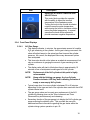
1
AtriCure Cryo Module
(ACM)
USER’S MANUAL
Model ACM1 – 115 VAC
Model ACM2 – 230 VAC
AtriCure, Inc.
6217 Centre Park Drive
West Chester, Ohio
45069
USA
P000669 Rev. D
European Representative:
Herbert Köntges
Köntges SPRL
Avenue Hellevelt 35
B-1180 Brussels Belgium
Tel: +32 2 375 51 63
FAX: +32 2 375 89 06
email: [email protected]
1
Table of Contents
1.
GETTING STARTED......................................................................................................... 4
1.1.
1.2.
1.3.
1.4.
1.5.
2.
THE ATRICURE CRYO MODULE (ACM) ..................................................................... 12
2.1.
2.2.
2.3.
3.
Transporting of ACM .......................................................................................... 22
Preparing the ACM For Use ............................................................................... 22
Installing Power Cord ......................................................................................... 22
Installing the Footswitch ..................................................................................... 22
Installing Cylinder Heater Band .......................................................................... 23
Installing N2O Gas Line Hose............................................................................. 24
Installing N2O Exhaust Hose .............................................................................. 26
Connecting and Disconnecting the Handpiece .................................................. 26
INSTRUCTIONS FOR USE ............................................................................................ 28
4.1.
4.2.
4.3.
4.4.
5.
Device Description ............................................................................................. 12
ACM Front Panel – Illustration and Nomenclature ............................................. 13
ACM Rear Panel – Illustration and Nomenclature .............................................. 19
INSTALLING THE ACM.................................................................................................. 22
3.1.
3.2.
3.3.
3.4.
3.5.
3.6.
3.7.
3.8.
4.
System Description .............................................................................................. 5
Unpacking ............................................................................................................ 6
Warnings and Precautions ................................................................................... 6
EMC Guidance and Manufacturer’s Declaration .................................................. 7
Responsibility of the Manufacturer ..................................................................... 11
Powering Up the ACM........................................................................................ 28
Operating Modes................................................................................................ 29
Delivering Cryo Energy ...................................................................................... 31
Parameter Entry Mode / Adjusting the System Default Parameter Values ......... 34
TROUBLESHOOTING .................................................................................................... 36
5.1.
5.2.
5.3.
5.4.
No ACM Power / Display Function ..................................................................... 36
ACM Fault Codes ............................................................................................... 36
ACM Error Codes ............................................................................................... 37
Handpiece Error Codes ...................................................................................... 38
6.
SYMBOLS USED ............................................................................................................ 39
7.
TECHNICAL SPECIFICATIONS .................................................................................... 42
7.1.
7.2.
7.3.
7.4.
7.5.
7.6.
8.
Mechanical Specifications .................................................................................. 42
Environmental Specifications ............................................................................. 42
Electrical Specifications ..................................................................................... 42
Fuses ................................................................................................................. 42
Footswitch Specifications ................................................................................... 42
Equipment Type / Classification ......................................................................... 42
PREVENTIVE MAINTENANCE AND CLEANING OF ACM ......................................... 43
8.1.
8.2.
Preventive Maintenance ..................................................................................... 43
Cleaning and Disinfecting .................................................................................. 44
2
9.
SERVICING OF ACM UNIT ............................................................................................ 45
9.1.
9.2.
9.3.
9.4.
9.5.
Replacement of AC Line Fuses ......................................................................... 45
Replacement of System Controller Board Fuses ............................................... 46
Replacement of In-Line N2O Filter ..................................................................... 47
Replacement of Gas Line Desiccant Filter ......................................................... 48
Other Replacement Components ....................................................................... 50
10. ACCESSORIES............................................................................................................... 51
10.1. CMH15, Cryo Module Cylinder Heater Band ..................................................... 51
10.2. CMH22, Cryo Module Cylinder Heater Band ..................................................... 51
10.3. CMF1, Cryo Module Footswitch ......................................................................... 51
11. DISPOSAL ....................................................................................................................... 51
3
1.
Getting Started
This manual and the equipment it describes are for use only by qualified medical
professionals trained in the particular technique and surgical procedure to be performed.
Caution: Federal (USA) law restricts this device to sale by or on the order of a
physician.
Please read all information carefully. Failure to properly follow the instructions may lead
to serious surgical consequences.
Important: This manual is designed to provide instructions for use of the AtriCure
Cryo Module (ACM) with the AtriCure Cryo Handpiece (CRYO1 and cryoICE) and
AtriCure Accessory Devices (CMF1, CMH15, CMH22). This manual is not a reference
to surgical technique.
The AtriCure Cryo Module (ACM) unit is an electro-mechanical and pneumatic cryogenic
surgical system that delivers a cryogenic energy source, namely Nitrous Oxide, to create
lines of ablation through cardiac tissue. The ACM is part of a system which includes the
nitrous oxide gas, N2O gas line hose, N2O exhaust hose, cylinder heater band, a
footswitch, and single-use cryo handpiece with integrated electronics cable / gas hoses.
The system provides controlled lesion forming temperature that is below -40°C, with
typical operating ranges between -50°C to -70°C. The system is also equipped with the
ability to tune or set the terminal handpiece temperature.
The ACM is designed to operate only with AtriCure designed and developed handpieces.
Along with the Ablation Activation Switch on the front panel of the ACM, a footswitch can
also be used to activate the ablation cycle. Refer to the handpiece Instruction for Use for
a complete description of the indications and uses of these devices.
For the user’s convenience, the AtriCure Cryo Module will be referred to in this User’s
Manual as the “ACM”. The AtriCure Cryo Handpiece will be referred in this User’s
Manual as the “Handpiece”.
This User’s Manual provides a description of the ACM, its controls, displays,
indicators, and a sequence for its operation with the Handpiece. This User’s Manual
also supplies other information of importance to the user. This manual is intended as a
User’s Manual only. Do not operate the ACM before thoroughly reading this manual.
4
1.1.
System Description
As shown in Figure 1, the system is comprised of the following:
•
A:
AtriCure Cryo Module Cylinder Heater Band (CMH15 or CMH22)
•
B:
AtriCure Cryo Footswitch
•
C:
ACM N2O Exhaust Hose
•
D:
ACM N2O Gas Line Hose
•
E:
AtriCure Cryo Module (ACM)
•
ACM Power Cord (not shown)
•
AtriCure Cryo Handpiece with integral cable (not shown)
Accessory devices are described in Section 10.
Figure 1 – ACM, Footswitch, N2O Gas Line Hose, N2O Exhaust
Hose, and Cylinder Heater Band
5
1.2.
Unpacking
1.2.1. ACM Unit
Lift the ACM unit from the box and remove the protective wrapping and side caps.
Note: The ACM unit is packed upside down for transit purpose.
Note: Take precautions when lifting the unit as it weighs approx 45 lbs (20 kg).
1.2.2. Accessories
ACM accessories are shipped separately from the ACM unit. The accessory box
contains the following items:
•
ACM Power Cord
•
N2O Gas Line Hose
•
N2O Exhaust Hose
•
ACM Cylinder Heater Band
•
ACM Footswitch
•
ACM User’s Manual
It is recommended that the original shipping box and protective wrapping be saved for
future storing and/or transporting of the device.
1.3.
Warnings and Precautions
The safe and effective use of the cryo device and equipment is highly dependent
upon factors under the control of the operator. There is no substitute for a properly
trained operating room staff. It is important that the operating instructions supplied
with the ACM unit be read, understood, and followed before use.
1.3.1. WARNINGS
•
Do not operate the ACM unit before thoroughly reading this manual.
•
Do not use cryo surgical equipment unless properly trained in the specific
procedure being undertaken. This manual and the equipment it describes are for
use only by qualified medical professionals trained in the particular technique and
surgical procedure to be performed.
•
Fire Hazard: Do not use extension cords.
•
Trip Hazard: Standard care should be used to reduce the risk of tripping on the
Footswitch cable, as well as the N2O exhaust hose.
The voltage selector is factory set and should not be changed by the user. The
voltage setting and the fuse rating must be appropriate as identified to prevent ACM
malfunction and potential instrument damage.
Electric Shock Hazard: Connect the ACM Power Cord to a properly grounded
receptacle. Do not use power plug adapters.
6
Electric Shock Hazard: Do not connect wet accessories to the generator.
Electric Shock Hazard: Ensure that the Handpiece is correctly connected to the
ACM and that no thermocouple wires are exposed from the cable, connector, or the
Handpiece.
1.3.2. PRECAUTIONS
•
Use only with the AtriCure Handpieces intended for use with the ACM.
•
Do not activate the ACM unit until the Handpiece is properly positioned at the
ablation site.
•
The system status indicators and displays are important safety features. Do not
obstruct either the ablation or the system status indicators.
Do not remove the ACM cover, except for the in-line gas filter access port, as
there is a potential for electrical shock. Refer to authorized personnel for service.
1.4.
•
Use only the Footswitch provided with the ACM.
•
The Power Cord of the ACM must be connected to a properly grounded
receptacle. Extension cords and/or adapter plugs must not be used.
EMC Guidance and Manufacturer’s Declaration
1.4.1. Electromagnetic Requirements
1.4.1.1.
The AtriCure Cryo Module (ACM) has been tested and found to comply
with the limits for medical devices in IEC 60601-1-2:2007. These limits are
designed to provide reasonable protection against harmful interference in a
typical medical installation.
1.4.1.2.
The ACM can radiate radio frequency energy and, if not installed and used
in accordance with the instructions, may cause harmful interference to
other devices in the vicinity.
1.4.1.3.
Portable and mobile RF communications equipment can also affect ACM
performance and care should be taken to minimize such interference.
However, there is no guarantee that interference will not occur in a
particular installation.
7
1.4.1.4.
If the ACM does cause harmful interference to other devices, which can be
determined by turning the ACM off and on, the user is encouraged to try to
correct the interference by one or more of the following measures:
•
Reorient or relocate the receiving device.
•
Increase the separation between the ACM and the other devices.
•
Connect the ACM into an outlet on a circuit different from that to which
the other device(s) are connected.
•
Contact the AtriCure service representative for help.
1.4.2. Electromagnetic Emissions
Guidance and manufacturer’s declaration – electromagnetic emissions
The AtriCure Cryo Module (ACM) is intended for use in the electromagnetic environment specified below.
The customer or the user of the ACM unit should assure that it is used in such an environment.
Emissions test
RF emissions CISPR 11
Compliance
Electromagnetic environment – guidance
Group 1
The ACM unit uses RF energy only for its internal
function. Therefore, its RF emissions are very low and
are not likely to cause any interference in nearby
electronic equipment.
RF emissions
CISPR 11
Class A
Harmonic emissions IEC
61000-3-2
Class A
Voltage fluctuations/
flicker emissions IEC
61000-3-3
The ACM unit is suitable for use in all establishments
other than domestic and those directly connected to
the public low-voltage power supply network that
supplies buildings used for domestic purposes.
Complies
8
1.4.3. Electromagnetic Immunity
Guidance and manufacturer’s declaration – electromagnetic immunity
The AtriCure Cryo Module (ACM) is intended for use in the electromagnetic environment specified below.
The customer or the user of the ACM unit should assure that it is used in such an environment.
IMMUNITY test
Electrostatic
discharge (ESD)
IEC 61000-4-2
Electrical fast
transient/burst
IEC 61000-4-4
IEC 60601 test level
± 6 kV contact
± 6 kV contact
± 8 kV air
± 8 kV air
± 2 kV for power
supply lines
± 2 kV for power
supply
Lines
± 1 kV for
input/output lines
Surge
IEC 61000-4-5
± 1 kV line(s) to
line(s)
Power frequency
(50/60 Hz)
magnetic field
IEC 61000-4-8
NOTE:
± 1 kV for
input/output
lines
± 1 kV differential
mode
<5 % UT
(>95 % dip in UT)
for 0,5 cycle
± 2 kV common
mode
<5 % UT
(>95 % dip in UT)
for 0,5 cycle
40 % UT
(60 % dip in UT)
for 5 cycles
40 % UT
(60 % dip in UT)
for 5 cycles
70 % UT
(30 % dip in UT)
for 25 cycles
70 % UT
(30 % dip in UT)
for 25 cycles
<5 % UT
(>95 % dip in UT)
for 5 s
3 A/m
<5 % UT
(>95 % dip in UT)
for 5 s
3 A/m
± 2 kV line(s) to earth
Voltage dips, short
interruptions and
voltage variations
on power supply
input lines
IEC 61000-4-11
Compliance level
Electromagnetic environment –
guidance
Floors should be wood, concrete,
or ceramic tile. If floors are
covered with synthetic material,
the relative humidity should be at
least 30 %.
Mains power quality should be that
of a typical commercial or hospital
environment.
Mains power quality should be that
of a typical commercial or hospital
environment.
Mains power quality should be that
of a typical commercial or hospital
environment. If the user of the
ACM unit requires continued
operation during power mains
interruptions, it is recommended
that the ACM unit be powered from
an uninterruptible power supply or
a battery.
Power frequency magnetic fields
should be at levels characteristic
of a typical location in a typical
commercial or hospital
environment.
UT is the a.c. mains voltage prior to application of the test level.
9
1.4.4. EMC Guidance and Manufacturer’s Declaration
Guidance and manufacturer’s declaration – electromagnetic immunity
The AtriCure Cryo Module (ACM) is intended for use in the electromagnetic environment specified below.
The customer or the user of the ACM should assure that it is used in such an environment.
IMMUNITY
test
IEC 60601 TEST
LEVEL
Compliance
level
Electromagnetic environment – guidance
Portable and mobile RF communications
equipment should be used no closer to any part of
the ACM, including cables, than the
recommended separation distance calculated
from the equation applicable to the frequency of
the transmitter.
Conducted RF
IEC 61000-4-6
3 Vrms
150 kHz to 80 MHz
Radiated RF
IEC 61000-4-3
3 V/m
80 MHz to 2.5 GHz
Recommended separation distance
3 Vrms
d = 1.2 √P
d = 1.2 √P 80 MHz to 800 MHz
3 V/m
d = 2.3 √P 800 MHz to 2.5 GHz
where P is the maximum output power rating of
the transmitter in watts (W) according to the
transmitter manufacturer and d is the
recommended separation distance in meters (m).
Field strengths from fixed RF transmitters, as
determined by an electromagnetic site survey,a
should be less than the compliance level in each
frequency range.b
Interference may occur in the vicinity of
equipment marked with the following symbol:
NOTE 1:
At 80 MHz and 800 MHz, the higher frequency range applies.
NOTE 2:
a
b
These guidelines may not apply in all situations. Electromagnetic propagation is affected by
absorption and reflection from structures, objects, and people.
Field strengths from fixed transmitters, such as base stations for radio (cellular/cordless) telephones
and land mobile radios, amateur radio, AM and FM radio broadcast and TV broadcast cannot be
predicted theoretically with accuracy. To assess the electromagnetic environment due to fixed RF
transmitters, an electromagnetic site survey should be considered. If the measured field strength in the
location in which the ACM is used exceeds the applicable RF compliance level above, the ACM
should be observed to verify normal operation. If abnormal performance is observed, additional
measures may be necessary, such as re-orienting or relocating the ACM.
Over the frequency range 150 kHz to 80 MHz, field strengths should be less than 3 V/m.
10
1.4.5. Recommended Separation Distance
Recommended separation distances between portable and mobile RF communications
equipment and the AtriCure Cryo Module
The AtriCure Cryo Module (ACM) is intended for use in an electromagnetic environment in which radiated
RF disturbances are controlled. The customer or the user of the ACM can help prevent electromagnetic
interference by maintaining a minimum distance between portable and mobile RF communications
equipment (transmitters) and the ACM as recommended below, according to the maximum output power of
the communications equipment.
Rated maximum
output power of
transmitter W
Separation distance according to frequency of transmitter m
150 kHz to 80 MHz
d = 1.2 √P
80 MHz to 800 MHz
d = 1.2 √P
800 MHz to 2.5 GHz
d = 2.3 √P
0.01
0.12
0.12
0.23
0.1
0.38
0.38
0.73
1
1.2
1.2
2.3
10
3.8
3.8
7.3
100
12
12
23
For transmitters rated at a maximum output power not listed above, the recommended separation distance
d in meters (m) can be estimated using the equation applicable to the frequency of the transmitter, where P
is the maximum output power rating of the transmitter in watts (W) according to the transmitter
manufacturer.
1.5.
NOTE 1:
At 80 MHz and 800 MHz, the separation distance for the higher frequency range applies.
NOTE 2:
These guidelines may not apply in all situations. Electromagnetic propagation is affected by
absorption and reflection from structures, objects, and people.
Responsibility of the Manufacturer
AtriCure is responsible for safety, reliability, and performance of the equipment only if:
• Installation procedures in this manual are followed.
•
Persons authorized by AtriCure carry out modifications or repairs.
•
The electrical installation of the relevant room complies with local codes and
regulatory requirements such as IEC and BSI.
•
The equipment is used in accordance with the AtriCure User’s Manual.
11
2.
The AtriCure Cryo Module (ACM)
This section provides a detailed description of the ACM including its function and
operating features.
2.1.
Device Description
• The AtriCure Cryo Module (ACM) unit is an electro-mechanical and pneumatic
cryogenic surgical system that delivers a cryogenic source, Nitrous Oxide, to
create lines of ablation through cardiac tissue.
• The ACM is part of a system which includes the nitrous oxide gas and its cylinder,
N2O gas line hose, N2O exhaust hose, cylinder heater band, a footswitch, system
power cord, and single-use cryo handpiece with integrated electronics cable / gas
hoses.
• The system provides a controlled lesion forming temperature that is below -40°C,
with typical operating ranges between -50°C to -70°C for the treatment of cardiac
arrhythmias, creating an inflammatory response (cryonecrosis) that blocks the
cardiac electrical conduction pathway.
• The system is also equipped with the ability to tune or set the terminal handpiece
temperature.
• Along with the Ablation Activation Switch on the front panel of the ACM, the ACM
Footswitch can also be used as the input device to activate and terminate the cryo
ablation cycle.
• The presence of the ACM Footswitch is not a requirement for the ACM unit to
operate and is made available as a secondary means of interfacing with the ACM
unit, and to provide control of the ablation cycle to the surgeon.
• The ACM is designed to operate only with AtriCure designed and developed
handpieces.
• Refer to the Handpiece Instruction for Use for complete description of the
indications and uses of these devices.
12
2.2.
ACM Front Panel – Illustration and Nomenclature
An illustration of the ACM front panel is shown in Figure 2, below.
Figure 2 – ACM Front Panel
1.
Ablation Activation Switch
7.
Ablation Timer Increment
2.
Ablation Status Indicator
8.
Handpiece Probe Temperature
3.
N2O Gas Gauge Display
9.
Handpiece Thermocouple Port
4.
System Status Indicator
10. Handpiece Electronic Interface Port
5.
Ablation Timer Decrement
11. Handpiece Gas Connection Port
6.
Ablation Timer Display
12. Handpiece Probe Temperature Control
2.2.1. Ablation Status Indicators
There are three indicators on the front panel of the ACM: READY, FREEZE,
and DEFROST. These indicators are described below.
1
2
3
13
Figure 3 – ACM Ablation Status Indicators
Indicator
Symbol
Description
READY – Green LED
1
This status indicates the ACM is in
stand-by mode and is ready to start the
cryo ablation cycle.
FREEZE – Blue LED
2
This status indicates the ACM is in cryo
freeze state and the N2O gas is allowed
to flow through the Handpiece causing
drop in probe temperature.
DEFROST – Amber LED
3
This status indicates the ACM is in
defrost state, N2O gas flow is ceased,
Handpiece is back pressurized, and the
Handpiece probe is warming back up to
the ambient temperature.
14
2.2.2. System Status Indicators
There are six system status indicators on the front panel of the ACM: SYSTEM
POWER, SYSTEM FAULT, MAINTENANCE NEEDED, LOW CYLINDER
PRESSURE, CYLINDER HEATER BAND ACTIVE, and FOOTSWITCH
ACTIVE. These indicators are described below.
2
1
3
4
5
6
Figure 4 – ACM Status Indicators
Indicator
Symbol
Description
SYSTEM POWER – Green LED
1
This status indicates system logic power
for the ACM is available.
SYSTEM FAULT – Red LED
2
This status indicates ACM has
encountered a system fault condition and
has halted all operation. The ACM unit will
not operate until the fault condition has
been addressed.
MAINTENANCE NEEDED – Amber LED
3
This status indicates the ACM system is still
in normal, functional, and safe operating
mode. However, maintenance is being
requested to address such items as
replacing in-line N2O gas filter to optimize
system performance.
15
Indicator
Symbol
Description
LOW CYLINDER PRESSURE – Amber
LED
This status indicates the N2O cylinder gas
pressure into the ACM unit is below (initial
system power up) or is dropping below
(during usage) the optimal operating level.
4
Two LED indication modes are available.
Initial Power Up:
Constant:
Indicates the cylinder pressure is still
below the optimal operating level.
Blinking:
Indicates cylinder valve is closed, or if
the valve is open, the cylinder
pressure is well below the operating
level or is empty of N2O gas.
• In both of these cases, the cylinder
heater band will be active to raise the
cylinder pressure to its recommended
operating level as long as the cylinder
valve is in the open position.
• The cylinder heater band will not be
active if the cylinder valve is in the
CLOSED position.
• The indicator LED will extinguish when
the cylinder pressure has reached its
optimal operating level.
During Usage:
Constant:
Indicates the cylinder pressure has
dropped below the optimal operating
level, and the cylinder heater band will
be activated. The indicator LED will
extinguish when the cylinder pressure
has risen back to the optimal
operating level.
Blinking:
Indicates the cylinder pressure is well
below the recommended operating
level, and the cylinder has less than
10 minutes of functional gas left.
16
Indicator
Symbol
Description
CYLINDER HEATER BAND ACTIVE –
Amber LED
This status indicates ACM unit has
energized the N2O cylinder heater band
and it is active. The indicator LED will
extinguish when the cylinder heater band
is turned off by the ACM unit.
5
FOOTSWITCH ACTIVE – Blue LED
This status indicates the ACM footswitch
pedal is depressed and is in activate state.
The indicator LED will extinguish when the
footswitch pedal is released.
6
2.2.3. Front Panel Functions
Item
Description
HANDPIECE THERMOCOUPLE
Receptacle
This 2-pin receptacle accepts the AtriCure
Handpiece thermocouple connectors. This
connection is patient-isolated.
HANDPIECE ELECTRONIC
INTERFACE Receptacle
This 14-pin receptacle is reserved for
future release of AtriCure Handpiece. This
connection is patient-isolated.
HANDPIECE PNEUMATIC Receptacle
This 2 port pneumatic receptacle provides
the N2O interface with the AtriCure
Handpiece. The ports are polarized to
prevent cross-coupling of the nozzles.
17
Item
Description
HANDPIECE PROBE TEMPERATURE
ADJUST Knob
This control knob provides the operator
with the ability to adjust the terminal
temperature of the handpiece probe.
Turning the knob in the counter-clockwise
rotation lowers the probe temperature,
while turning the knob in clockwise rotation
raises the probe temperature. In normal
operation the knob will be adjusted to
provide maximum negative temperature.
2.2.4. Front Panel Displays
2.2.4.1.
N2O Gas Gauge
•
This display indicates, in minutes, the approximate amount of useable
N2O gas remaining in the cylinder. As the gas is being consumed, this
value will adjust based on the actual gas flow time and the cylinder
pressure. As a result, the displayed value many decrement quicker
than anticipated.
•
This time value should not be taken as an absolute measurement, but
only as a reference in gauging the amount of gas remaining in the
cylinder.
•
The display value will start to blink when there is approximately 10
minutes or less of anticipated useable gas left in the cylinder.
NOTE:
Replacement of the N2O cylinder at this point is highly
recommended.
NOTE:
Along with the blinking gas gauge, the Low Cylinder
Pressure indicator LED may also be blinking indicative of
empty or near empty N2O cylinder.
•
Typical usage time for a new cylinder is between 30 to 40 minutes
depending on the type and size of the cylinder when used with the ACM
cylinder heater band.
•
The gas gauge value can be reset upon replacement of the N2O
cylinder by pressing down on the Timer Increment and Timer
Decrement key simultaneously and releasing.
•
Secondary function of the gas gauge is to display the N2O cylinder gas
pressure during the ablation cycle. This provides the user with
additional real-time information regarding the gas status within the
cylinder during system operation in psi x10.
18
2.2.4.2.
2.2.4.3.
2.3.
Ablation Timer
•
This display indicates the desired ablation duration in units of seconds.
•
The default duration time is 120 seconds per ablation run.
•
This timer value can be adjusted prior to, or during the ablation cycle,
by using either the Timer Increment or Timer Decrement key pad.
•
Each key press of the Timer Increment or Timer Decrement will modify
the target ablation time value by 10 seconds; either adding or
subtracting from its present value.
•
At the termination of the freeze cycle (Defrost mode), the display will
show total time in freeze state. A full 120 second run will result in the
display showing 120 as an example. An aborted freeze cycle will show
the number of seconds the system operated in the Freeze mode.
Handpiece Probe Temperature
This display indicates the current handpiece probe temperature in Celsius,
and is continuously updated each second.
ACM Rear Panel – Illustration and Nomenclature
An illustration of the ACM rear panel is shown in Figure 5, below.
Figure 5 – ACM Rear Panel
1. N2O Exhaust Port
5. Equipotential Terminal
2. System Pressure Relief Knob
6. Cylinder Heater Band Receptacle
3. N2O Inlet Port
7. AC Power Entry Module
4. Footswitch Receptacle
8. Input Voltage Selector Switch
Note: Input Voltage Level Switch is factory set and is covered by unit model label. The
switch and the label should not be tampered with or changed except by an authorized
AtriCure personnel.
19
2.3.1. Rear Panel Functions
Item
Description
Power Entry Module –
This module contains both the ON/OFF
switch and the fuses.
Fuse Box –
The Fuse Box contains fuses selected for
the input voltage. See Technical
Specifications in Section 7 of this manual.
Cylinder Heater Band Receptacle –
This receptacle accepts the ACM Cylinder
Heater Band connector. It provides power
for the heating element embedded in the
heater band, as well as transmitting back
to the ACM unit the N2O cylinder wall
temperature.
Footswitch Receptacle –
This receptacle accepts the ACM
Footswitch connector. The single
momentary actuation pedal provides for
the activation and termination of the cryo
ablation cycle.
N2O Inlet Receptacle –
This receptacle accepts the N2O gas line
hose with the quick connect / disconnect
interface used to transfer gas from the
N2O gas cylinder to the ACM unit to be
utilized by the Handpiece.
20
Item
Description
N2O Exhaust Receptacle –
This ½ inch (1.25cm) receptacle accepts
the 50 ft (15 m) flexible tubing to direct the
expelled N2O gas in a manner appropriate
with local and hospital regulation.
System Pressure Relief Knob –
This knob, when pulled, will depressurize
and expel any trapped N2O gas within the
ACM unit at any time.
Be sure the N2O cylinder valve is
CLOSED prior to performing this task.
Equipotential Terminal –
This terminal provides a means of
securely linking the earth ground of the
AtriCure ACM unit to other grounded
equipment.
21
3.
Installing the ACM
Inspect the ACM system for any signs of physical damage to the front and rear panel,
N2O gas couplers, connector receptacles, chassis or cover.
NOTE: If any physical damage is found, DO NOT USE THE UNIT. Contact
AtriCure for a replacement.
All returns must be approved by AtriCure.
3.1.
Transporting of ACM
The use of handles is highly recommended in lifting, carrying, or moving of the ACM unit.
The ACM weighs approximately 45 lbs (20 kg) so care should be taken when
transporting the ACM unit.
3.2.
Preparing the ACM For Use
3.2.1. The ACM unit may be placed on a cart or on any sturdy table or platform. It is
recommended that carts have conductive wheels. Refer to hospital procedures or
local codes for detailed information.
3.2.2. The ACM unit may be placed together or stacked with other AtriCure capital
equipment such as the ASU, ASB, and the ORLab. However, care must be taken
when stacking or placing the ACM unit adjacent to other medical equipment and
unit performance should be observed to verify normal operation in the
configuration in which it will be used.
3.2.3. Provide at least four to six inches of space around the sides of the ACM for
convection cooling. Under continuous use for extended periods of time, it is
normal for the top panel to be warm to the touch.
3.3.
Installing Power Cord
The ACM unit is shipped with an approved hospital grade power cord.
Insert the power cord into the power entry module of the ACM unit as shown in Figure 7,
and then into a grounded hospital AC power receptacle.
NOTE: ACM power cord is shipped with the accessories and found in the accessory
package.
NOTE: Do not use extension cords or three-prong to two-prong adapters. The Power
Cord assembly should be periodically checked for damaged insulation or
connectors.
3.4.
Installing the Footswitch
3.4.1. Inspect the Footswitch
Inspect the Footswitch for any signs of physical damage to the cable and
connector. If physical damage is found or the Footswitch does not perform within
specification, contact AtriCure for replacement.
22
3.4.2. Connecting and Disconnecting the Footswitch
With the connector alignment arrow in the 12 o’clock position, push the Footswitch
Connector into the Footswitch Receptacle on the rear panel of the ACM as shown
in Figure 7. To disconnect, firmly grasp the connector body and pull out from the
Footswitch Receptacle.
NOTE: Typically, you will connect the Footswitch to the ACM prior to powering up the
unit. However, the Footswitch may be connected to the ACM when the unit is
powered up and is in READY operating mode (see Section 4 regarding the
READY mode).
3.4.3. Preparing the Footswitch for Use
The Footswitch should be placed on a flat floor. It is recommended that the area
near the Footswitch be kept dry to reduce the risk of slippage.
Appropriate precautions should be taken to ensure that the cable connecting the
Footswitch to the ACM does not create a hazard in the operating room.
3.5.
Installing Cylinder Heater Band
3.5.1. Inspect the Cylinder Heater Band
Inspect the Cylinder Heater Band for any signs of physical damage to the cable
and connector. If physical damage is found or the Cylinder Heater Band does not
perform within specification, contact AtriCure for replacement.
3.5.2. Wrapping the Cylinder Heater Band
Place the Cylinder Heater Band around the N2O cylinder, and secure all 6
tensioning spring retainers as shown in Figure 6. Start with the top and bottom
spring retainers.
NOTE: Cylinder Heater Band should be positioned approximately 2.0 inch (5.0 cm)
from the cylinder bottom for optimal performance.
Figure 6 – Cylinder Heater Band Installation
23
3.5.3. Connecting and Disconnecting the Cylinder Heater Band
With the connector alignment arrow in the 12 o’clock position, push the Cylinder
Heater Band Connector into the Cylinder Heater Band Receptacle on the rear
panel of the ACM as shown in Figure 7. To disconnect, firmly grasp the connector
body, push down on the locking latch, and pull out from the Cylinder Heater Band
Receptacle.
NOTE: Cylinder Heater Band must be connected to the ACM prior to powering up the
unit. However, the ACM unit can operate without the Cylinder Heater Band in
place but the system performance will not be optimal.
NOTE: It is highly recommended that the ACM unit and the cylinder heater band be
activated at least 15 minutes prior to first use to allow for the cylinder pressure to
reach optimal operating level.
Figure 7 – Connecting the Footswitch, Cylinder Heater Band, and Power Cord to ACM
3.6.
Installing N2O Gas Line Hose
3.6.1. Inspect the N2O Gas Line Hose
Inspect the N2O Gas Line Hose for any signs of physical damage to the hose and
pneumatic connectors on both ends, including pressure gauge and the desiccant
filter assembly. If physical damage is found do not use the N2O Gas Line Hose
and contact AtriCure for replacement.
3.6.2. Connecting and Disconnecting the N2O Gas Line Hose with ACM unit
• Align the quick-connect gas connector from the gas hose line with the ACM
N2O inlet port.
• Insert and push in the connector until you hear it “click” in place and the
connection is fully seated and secured from unlatching.
• To disconnect the N2O gas line connector from the ACM, slide back on the
N2O inlet port connector sleeve and remove. See Figure 8.
24
NOTE: The N2O cylinder valve should be in the CLOSED position during
connection and disconnection from the ACM unit.
Figure 8 – Aligning the N2O gas line quick connect to the ACM N2O inlet port
3.6.3. Connecting and Disconnecting the N2O Gas Line Hose with Gas Cylinder
• Align the CGA326 hand knob (or equivalent coupler) from the gas hose line
with the gas cylinder’s threaded connection port, and screw in place by turning
the hand knob in clockwise rotation.
NOTE:
•
The desiccant filter should be positioned vertically in-line with the N2O
gas cylinder as shown below.
Hand tighten the connection and verify there is no leak when cylinder valve is
opened.
25
•
•
•
3.7.
If a leak is detected, tighten the hand knob connection further. A wrench may
be needed to tighten the connection.
If the leak cannot be eliminated, either the N2O gas line hose or the N2O gas
cylinder may need to be replaced.
To disconnect from the gas cylinder, turn the hand knob in a counter-clockwise
rotation until the connection is disengaged.
Installing N2O Exhaust Hose
• Align the 50 ft (15m) exhaust hose with the N2O Exhaust port of the ACM and push
in place.
• Run the exhaust hose to an appropriate venting mechanism that meets the hospital
and local regulation.
• To remove the exhaust hose from the ACM unit, simply pull back on the tubing until it
releases. See Figure 9.
NOTE: It is not necessary or required for the N2O Exhaust Hose to be removed from
the ACM unit at the end of the procedure. The hose may be left in place.
Figure 9 – Connecting the N2O gas line hose and N2O exhaust hose to the ACM
3.8.
Connecting and Disconnecting the Handpiece
• Connect the Handpiece directly to the ACM.
• Insert the Handpiece pneumatic interface connectors into the pneumatic
receptacles on the front panel of the ACM, ensuring that each pneumatic inlet and
exhaust connection is fully seated and secured.
• Insert the thermocouple connectors into their respective color coded connection
ports on the front panel of the ACM. See Figure 10.
26
NOTE: Typically, you will connect the Handpiece to the ACM when the ACM has
been powered up and is in READY operating mode (see Section 4.2
regarding the READY mode). However, the Handpiece may be connected
when powered up, or prior to powering up the ACM.
NOTE: Once the Handpiece has been connected, it cannot be disconnected from the
ACM by pulling on the cable. To disconnect the Handpiece, slide back on the
pneumatic connector sleeve and remove it from the ACM pneumatic
receptacle.
NOTE: Connection and disconnection of the Handpiece with the ACM unit should
take place with the ACM unit in the READY state and the N2O cylinder valve
in the CLOSED position.
NOTE: Refer to the Handpiece instruction sheet for more detailed information about
connecting the Handpiece to the ACM in a sterile environment.
Figure 10 – Connecting the Handpiece to the ACM
27
4.
Instructions For Use
4.1.
Powering Up the ACM
1. Ensure that the ACM has been plugged into a proper hospital power receptacle.
NOTE: Do not use extension cords or three-prong to two-prong adapters where
applicable. The power cord assembly should be periodically checked for
damaged insulation or connectors.
2. Apply power to the ACM unit by flipping the ON/OFF power switch located on the
power entry module at the rear panel. The GREEN LED on the power switch should
energize if power is being applied to the system.
3. The ACM unit will go through a system Power On Self Test (POST). If POST
passes, the system transitions to the READY mode. If any portion of the POST fails,
the system transitions to the FAULT mode.
NOTE: Refer to Section 4.2., below, for a full description of the READY and FAULT
modes, as well as all the other operating modes.
4. It is highly recommended that the ACM system be prepared and powered up well in
advance of start of the procedure to verify its operational readiness as well as
preheating of N2O cylinder gas pressure to raise it to its optimal performance level.
NOTE: N2O cylinder valve must be open for the system to detect its presence and to
start the preheating cycle.
28
4.2.
Operating Modes
The ACM operates in one of five modes: READY, FREEZE, DEFROST, ERROR and
FAULT modes. These modes are identified by the system status indicator LEDs and the
ablation status indicator LEDs located on the front of the ACM unit. See Figure 11,
below.
4.2.1.
READY Mode – This mode is entered automatically upon successful
execution of Power On Self Test when the unit is first turned on, or
following DEFROST Mode upon venting of the Handpiece by depressing
the Ablation Activation Switch or the Footswitch. This indicates that the
system is ready for the next cryo ablation run.
4.2.2.
FREEZE Mode – This Mode is entered from the READY Mode when the
user initiates the cryo ablation cycle by pressing the Ablation Activation
Switch or depressing and releasing the Footswitch. In this mode the N2O
gas is allowed to cycle through the handpiece causing a temperature drop
to take place at the handpiece probe.
4.2.3.
DEFROST Mode – This Mode is entered automatically from FREEZE
Mode upon expiration of the ablation timer, or manually by the operator
when the Ablation Activation Switch or the Footswitch is depressed while in
the FREEZE Mode. In this mode the handpiece probe temperature is
actively forced towards the ambient temperature.
Once the handpiece temperature has reached 10°C or higher, the
DEFROST status LED start to blink to indicate to the user the ACM unit is
ready to transition back to the READY Mode or return to the FREEZE
Mode to start the next ablation cycle.
The ACM unit can be returned to the FREEZE Mode by pressing and
releasing the Ablation Activation Switch or depressing and releasing the
Footswitch, which causes the handpiece to vent and start the freeze cycle
again.
The ACM unit can be returned to the READY Mode by pressing the
Ablation Activation Switch or depressing the Footswitch and holding it in
place for 2 seconds or longer. The ACM unit will automatically vent and
depressurize the handpiece. Once depressurized, the Ablation Activation
Switch or the Footswitch can be released.
NOTE: Handpiece probe temperature may drop temporarily during
depressurization phase (transition from Defrost to Ready state).
29
4.2.4.
ERROR Mode – This Mode is entered upon detection of any recoverable
error conditions during any Mode excluding the FAULT Mode. The ACM
unit will display the corresponding error message when in READY Mode,
and may halt operation temporarily upon detection of the error condition.
These are non-fatal self remedying errors and does not impact continue
use of the system. System Maintenance LED will be active to alert the
user that an error condition has occurred.
To reset the Maintenance LED hold down both the Timer Increment and
Timer Decrement button and power cycling the unit. The system will
undergo power-on self test for system functionality confirmation and return
to the operating state if appropriate.
4.2.5.
FAULT Mode – This Mode is entered upon detection of any unrecoverable
error condition during any Mode. The system is inoperable in this Mode
until the power is cycled off, then on, and only if the fault condition no
longer exists or has been remedied.
To reset the Fault LED hold down both the Timer Increment and Timer
Decrement button and power cycling the unit. The system will undergo
power-on self test for system functionality confirmation and return to the
operating state if appropriate.
30
4.3.
Delivering Cryo Energy
4.3.1. Connect the Handpiece, Pneumatics, Cylinder Heater Band, and Footswitch
Connect the Handpiece, N2O Gas Line Hose, N2O Exhaust Hose, Cylinder Heater
Band, and Footswitch as described in Sections 3.4. through 3.8., and note no
errors are indicated by the ACM unit. The ACM should indicate that the system is
in the READY mode, and the display showing ablation parameters. See Figure
11.
If a Handpiece or the Handpiece thermocouple is not connected, the ACM unit will
indicate such by displaying an error message in the probe temperature display
window with “E-H”. See Figures 12A and 12B.
Figure 11 – ACM Indicating READY Mode
Figure 12A – ACM Indicating Missing Handpiece Thermocouple
31
Figure 12B – ACM Indicating Missing Handpiece
4.3.2. Position the Handpiece
To position the Handpiece, follow the Instructions for Use provided with the
Handpiece.
4.3.3. Delivery of Cryo Energy
1. To start the cryo ablation cycle, simply press the Ablation Activation Switch
or depress and release the Footswitch. The ACM unit’s Ablation Status
Indicator LED will transition from Ready to Freeze.
2. N2O starts to flow through the ACM pneumatics and into the cryo ablation
handpiece, and the probe temperature starts to drop.
3. Upon probe temperature dropping below the set threshold (value is
programmable with default value of -40°C) the ablation timer starts its
decrement from a preset value (this value is also programmable with default
value of 120 s).
NOTE: The Freeze Mode can be manually terminated at any moment by
pressing the Ablation Activation Switch or depressing and releasing
the Footswitch, causing the ACM unit to transition into Defrost
Mode.
NOTE: The Ablation Timer value can be manually adjusted from its start
value either prior to the start of the ablation cycle or during the
freeze cycle using the Timer Increment and Timer Decrement key
pad. Each key press increments or decrements the timer value by
10 seconds.
NOTE: The factory default values of 120 seconds for ablation duration and
-40°C for the probe temperature threshold value can be altered by
the operator, and set as a site default values, following the
parameter entry procedure as defined in Section 4.4.
4. When the ablation timer reaches zero, the ACM unit automatically
transitions into Defrost Mode. As it transitions into the Defrost Mode, the
Ablation Timer display will now show the actual total ablation run time. The
ACM unit’s Ablation Status Indicator LED will transition from Freeze to
Defrost.
32
5. At this point, the ACM unit can be made to transition into one of two modes:
Freeze Mode or Ready Mode.
Defrost to Freeze:
Press and release the Ablation Activation Switch or depress and release
the Footswitch.
The ACM unit’s Ablation Status Indicator LED will transition from Defrost
back to Freeze and the ablation cycle starts again. As it transitions back
to the Freeze Mode, the Ablation Timer display also resets to the target
ablation time value.
Defrost to Ready:
Press and hold the Ablation Activation Switch or depress and hold the
Footswitch until the ACM unit vents and depressurizes the handpiece.
The ACM unit’s Ablation Status Indicator LED will transition from Defrost
back to Ready. As it transitions back to the Ready Mode, the Ablation
Timer display also resets to the target ablation time value.
Once the Handpiece has been depressurized, it is ready for the next
ablation run, which may take place immediately thereafter.
NOTE: The transition from Defrost to either Freeze Mode or Ready Mode
will not occur until the probe temperature has reached above 10°C.
Actuation of the Ablation Activation Switch or the Footswitch when
the probe temperature is below 10°C is simply ignored by the ACM
unit.
NOTE: The Defrost status LED will start to blink indicating to the operator
when the ACM unit is ready to transition back to either the Freeze
Mode or the Ready Mode.
NOTE: Handpiece probe temperature may drop temporarily during
depressurization phase (transition from Defrost to either Freeze
Mode or Ready Mode).
4.3.4. Powering down the ACM
Upon completion of the procedure, the ACM unit can be powered down.
NOTE: Verify that the ACM unit is in the Ready Mode prior to powering down
the unit.
If the unit is not in the Ready Mode, cycle the ACM by continuously
pressing the Ablation Activation Switch or depressing the Footswitch
until the unit returns to the Ready Mode.
CAUTION:
Do not remove cryo handpiece from the the ACM unit if the ACM
has been powered down prior to the system being in the Ready
Mode as N2O gas may be trapped within the cryo handpiece
interface and the handpiece couplers may still be under pressure.
33
To remove any trapped N2O gas, turn the ACM unit back ON.
As the unit cycles through the Power On Self Test (POST), it will
purge any trapped N2O gas within the cryo handpiece interface.
Upon completion of POST, and the ACM unit enters the Ready
Mode, the unit may now be powered down, and the cryo
handpiece removed from the ACM unit safely.
1. Close the N2O gas cylinder valve.
2. Depressurize the ACM unit by pulling on the Pressure Relief Valve Knob
located in the rear of the unit. This will remove any excess N2O that may be
trapped within the ACM pneumatic system.
3. Unplug the power cord from the hospital mains outlet, and disconnect from
the ACM unit.
4. Disconnect cryo handpiece from the ACM unit and dispose properly.
5. Disconnect N2O gas line hose from the ACM unit and N2O cylinder.
6. Loosen all 6 cylinder heater band tensioning springs and remove from the
N2O cylinder. Disconnect the cylinder heater band connector from the ACM
unit.
7. Disconnect the footswitch from the ACM unit.
8. Return ACM unit, its accessories, and N2O cylinder back to proper storage.
4.4.
Parameter Entry Mode / Adjusting the System Default Parameter Values
1. Power up the ACM unit. The system will go through its Power On Self Test (POST)
routine.
2. Upon completion of POST, press and hold down the Ablation Activation Switch for
approximately three seconds and release.
3. The User Display will start to blink indicating entry into the parameter entry mode.
4. There are two parameters that can be modified by the operator:
•
Ablation Timer / Duration: Freeze duration value in seconds
•
Probe Temperature Threshold: Temperature value at which the ablation timer
starts its countdown sequence
5. Ablation Timer / Duration Adjustment
•
Using the Timer Increment and the Timer Decrement key pad adjust the timer
value until the desired time value is shown. The displayed value corresponds to
the desired length of freeze time in units of seconds. Valid range is from 010 to
300 seconds in 10 second increments.
•
Once the desired time value is displayed, press the Ablation Activation Switch
to accept the value.
34
•
The system will now start blinking the display of the probe temperature
threshold parameter.
6. Probe Temperature Threshold
•
This value is used by the system to start the ablation timer countdown when the
probe temperature has dropped below the set threshold value.
•
Using the Timer Increment and the Timer Decrement key pad adjust the probe
temperature threshold value until the desired temperature value is shown. The
displayed value corresponds to the desired probe temperature threshold value
in units of degrees Celsius. Valid range is from -10°C down to -70°C in 5°C
increments.
•
Once the desired temperature value is displayed, press the Ablation Activation
Switch to accept the value.
7. The entry of the parameter value is now complete, and the system exits the
parameter entry mode and returns to the operating mode with the new set of
parameters.
8. Factory Default
•
The ACM unit can have its parameter values reset to its factory default setting
at any time.
•
To restore the factory default parameter values, power down the ACM unit.
•
Hold down the Ablation Activation Switch and power up the ACM unit.
•
A letter “P” will be displayed in the N2O Gas Gauge display. Release the
Ablation Activation Switch and the system will now go through its Power On Self
Test (POST) routine.
•
Upon completion of system POST, the unit returns to its normal operational
state and the system has restored all of the parameters back to the original
factory default values.
9. Factory default values are:
•
Ablation Timer / Duration = 120 seconds
•
Probe Temperature Threshold = -40°C
35
5.
Troubleshooting
Use the following sections to help troubleshoot possible problems with the ACM.
5.1.
No ACM Power / Display Function
If there is no ACM power or display function, attempt to correct this problem using the
following checklist.
Possible Cause
5.2.
Solution
ACM not turned on
Turn power on
ACM not plugged in
Confirm electrical connections and then turn power on
Blown fuse
Replace fuse, confirm electrical connections and turn power on.
Internal ACM failure
Contact AtriCure Customer Service
ACM Fault Codes
If a fault condition should occur, the N2O Gas Gauge display on the front panel will
display the following fault code. Use the table below to attempt to resolve the errors.
DISPLAY
MESSAGE
P1
DESCRIPTION
SOLUTION
System 24V out of range
Replace Fuse, or
System Controller Board – Fuse F2 blown
Contact AtriCure Customer
Service for support
N2O cylinder temperature high
Wait for N2O gas cylinder to cool
down, or
N2O gas cylinder likely empty.
Replace with new N2O gas
cylinder
Replace In-line N2O gas filter, or
P2
In-line N2O gas filter clogged
P3
Contact AtriCure Customer
Service for support
Cold junction temperature out of range
System Controller Board
requires service.
P4
Contact AtriCure Customer
Service for support
36
5.3.
ACM Error Codes
If an error condition should occur, the N2O Gas Gauge display on the front panel will
display the following error code while the ACM unit is in the READY Mode. System
Maintenance Needed indicator LED will also be lit. Use the table below to attempt to
resolve the following application errors.
DISPLAY
MESSAGE
E1
DESCRIPTION
No 230VAC to the cylinder heater band
Replace Fuse, or
System Controller Board – Fuse F1 blown
Contact AtriCure Customer
Service for support
System Controller Board
requires service.
No cylinder heater band voltage
E2
SOLUTION
System Controller Board – Triac
inoperative
Handpiece pressure regulator out of
range
Contact AtriCure Customer
Service for support
Handpiece Pressure Regulator
requires service.
E3
In-line N2O gas filter dirty
Contact AtriCure Customer
Service for support
Replace In-line N2O Gas Filter,
or
E4
No cylinder heater band current
Cylinder heater band
E5
•
•
Heating element malfunction, or
Thermal cutoff switch was activated
(heater band reached 65°C)
Caution: cylinder heater band may be hot
to the touch.
Contact AtriCure Customer
Service for support
Verify Cylinder Heater Band is
wrapped around the N2O gas
cylinder, or
Replace Cylinder Heater Band if
defective heating element is
determined, or
Contact AtriCure Customer
Service for support
37
5.4.
Handpiece Error Codes
If Handpiece related error condition should occur, the Probe Temperature display on the
front panel will display the following error code. Use the table below to attempt to resolve
the following application errors.
DISPLAY
MESSAGE
E-H
E-L
HI
LO
DESCRIPTION
SOLUTION
READY Mode Only
Handpiece Not Connected.
Connect Handpiece
Thermocouple Connection
READY Mode Only
Defective Thermocouple.
Replace Handpiece.
READY Mode Only
Defective Thermocouple.
Replace Handpiece.
DEFROST Mode Only
Probe temperature has risen above the
operating limit.
Replace Handpiece.
If Problem Repeats, Contact
AtriCure Customer Service.
FREEZE Mode Only
Probe temperature has dropped below
operating limit.
Replace Handpiece.
If Problem Repeats, Contact
AtriCure Customer Service.
38
6.
Symbols Used
Attention: consult accompanying
documents
Dangerous Voltage
Power OFF
Power ON
Alternating Current
~
Fuses
Equipotential Terminal
Type CF Applied Part
Start
READY
FREEZE
DEFROST
Gas Gauge (Time Remaining)
Timer
39
Timer Decrement
Timer Increment
Probe Temperature
Connector
Gas Inlet
Gas Outlet
Temperature Adjust
Gas Exhaust
Power
Maintenance Needed
Low Gas Pressure
40
Cylinder Heater Band
Footswitch
41
7.
Technical Specifications
7.1.
Mechanical Specifications
• Size:
17.5 in (W) × 27.0 in (D) × 4.5 in (H) maximum
44.5 cm (W) × 68.6 cm (D) × 11.4 cm (H) maximum
•
7.2.
7.3.
50 lb. (23 kg) absolute maximum.
Environmental Specifications
• Operational temperature:
+10°C to +40°C
•
Storage and Transit temperature:
–35°C to +54°C
•
Humidity:
15 to 90% relative humidity
Electrical Specifications
• ACM1: 100-120VAC, (115 VAC nominal), 50/60 Hz
•
7.4.
Weight:
ACM2:
220-240VAC, (230 VAC nominal), 50/60 Hz
Fuses
• 100 -120VAC, 50 / 60 Hz,: Replace fuses as marked:
4.0A/250V, T-lag, 5 × 20 mm, UL Recognized, IEC Approved
•
220-240VAC, 50 / 60 Hz,: Replace fuses as marked:
2.0A/250V, T-lag, 5 × 20 mm, UL Recognized, IEC Approved
7.5.
Footswitch Specifications
• Moisture protection rating: IPX8
7.6.
Equipment Type / Classification
• Class 1 Equipment
42
8.
Preventive Maintenance and Cleaning of ACM
8.1.
Preventive Maintenance
Perform annual preventative maintenance procedures to ensure all ACM components
are functioning as defined within this manual. Pay particular attention to operational and
safety features, including but not limited to:
•
Electrical power cords for fraying, damage, and proper grounding
•
AC power switch
•
Indicator damage (Power On, Fault, Maintenance Needed, Low Cylinder Pressure,
Cylinder Heater Band Active, Footswitch Active, Ready, Freeze, Defrost)
•
N2O Gas Gauge display damage or loss of information
•
Ablation Timer display damage or loss of information
•
Temperature display damage or loss of information
•
Handpiece electronic interface connector damage, cracking or inability to insert and
latch Handpiece connector
•
Handpiece pneumatic interface connector damage or inability to insert and latch
Handpiece pneumatic connector
•
Carrying handle damage or inability to fold
•
Rubber feet damage, cracking or inability for the ACM to remain stable on a flat
surface.
•
Rubber alignment cup damage, cracking or inability for the ASB/ASU to remain stable
atop ACM and within the alignment cup.
•
Footswitch cord fraying or damage
•
Footswitch connector damage cracking or inability to insert and latch footswitch plug
•
Footswitch pedal damage, check activation by pressing and releasing the pedal
Other medical equipment that may be used simultaneously with the ACM should also be
inspected for damage. Specifically, check for insulation damage of electrical cables and
associated connectors.
Visually inspect the footswitch for fluids or other infectious hazards. Clean as necessary
using the instructions in Section 8.2.
The ACM does not have any customer serviceable parts aside from fuses and gas filter.
For servicing issues, contact AtriCure, Inc. at:
6217 Centre Park Drive
West Chester, Ohio 45069
USA
Telephone: 513-755-4100
866-349-2342 Toll Free
43
8.2.
Cleaning and Disinfecting
8.2.1. ACM Cleaning and Disinfection Instructions
Use a mild detergent and damp cloth to clean the ACM enclosure, front and rear
panel, N2O exhaust tube, N2O gas line hose, and power cable. The ACM and
associated accessories cannot be sterilized. Do not allow fluids to enter the
enclosure. The ACM and associated accessories may be disinfected using a
standard hospital alcohol solution applied with a cloth.
NOTE: Do not spray or pour liquids directly on the unit.
8.2.2. Footswitch Cleaning and Disinfection Instructions
Use a mild detergent (prepared to its specifications) and a damp cloth to clean the
exterior of the Footswitch and cord. Do not allow fluids to enter the chassis. Take
care not to wet the electrical connector on the cable. Do not use caustic,
corrosive, or abrasive cleaning materials. The Footswitch cannot be sterilized.
The Footswitch may be disinfected using a standard hospital alcohol solution
applied with a cloth.
8.2.3. Cylinder Heater Band Cleaning and Disinfecting Instructions
Use a mild detergent (prepared to its specifications) and a damp cloth to clean the
exterior of the Cylinder Heater Band and its device cord. Take care not to wet the
electrical connector on the cable. Do not use caustic, corrosive, or abrasive
cleaning materials. The Cylinder Heater Band and its device cable cannot be
sterilized. The Cylinder Heater Band may be disinfected using a standard hospital
alcohol solution applied with a cloth.
44
9.
Servicing of ACM Unit
The ACM unit does not have any customer serviceable parts aside from fuses and gas
filter. The manufacturer does not require or recommend routine calibration / output
verification.
As stated in Section 4, the ACM performs its own maintenance check every time it is
powered ON. The check is called the Power On Self Test (POST). No calibration is
needed for the system and the unit will generate an error if further maintenance is
required.
Following identifies servicing that can be performed on the ACM unit based on Section 5,
Troubleshooting guide.
9.1.
Replacement of AC Line Fuses
9.1.1. Tools and Parts
•
•
Needle Nose Pliers
Fuses:
ACM Model
Fuse Type
ACM1
T 4A L 250V
ACM2
T 2A L 250V
Manufacturer
Schurter
Schurter
Part Number
0034.5049
0034.5046
9.1.2. Procedure
The ACM unit has been pre-set at the factory to either 110V – 120V (ACM1) or
220V – 240V (ACM2). The Rating Label below the Power Entry Module on the
back panel of the ACM indicates the selected Input Voltage for this unit. This
setting should only be adjusted by the manufacturer or by an authorized AtriCure
technical service representative.
NOTE:
ACM unit should be powered off and unplugged before continuing with
the fuse replacement procedure.
1. Determine the fuse type by looking at the ACM Model Number or the ACM Rating
Label.
2. Using the needle nose pliers, carefully extract the fuse box from the power entry
module by squeezing down on the fuse box tabs in the slots as shown.
45
3. Replace the (2) two fuses located in the fuse box. Make sure the fuses are lined
up straight.
4. Line up the fuse cartridge so the guide tab is towards the power entry side as
shown.
5. Slide the fuse box back into the power entry module and seat it firmly.
6. Confirm operational status by plugging in the ACM and powering it up. Check to
see that the self-test is completed without errors.
9.2.
Replacement of System Controller Board Fuses
9.2.1. Tools and Parts
• Fuse Extractor
• 3/32 inch Allen Wrench
• Fuses:
System Controller
Fuse Type
F1
T 1.6A 250V
F2
T 1.6A 250V
F3
T 1.6A 250V
Manufacturer
Littlefuse
Littlefuse
Littlefuse
Part Number
021801.6HXP
021801.6HXP
021801.6HXP
9.2.2. Procedure
NOTE:
ACM unit should be powered off and unplugged before continuing with
the fuse replacement procedure.
1. Turn over the ACM unit so that the bottom side is up.
2. Remove the 6 screws holding the bottom cover in its place using the 3/32 inch
Allen wrench.
3. Using the fuse extracting tool, remove the appropriate fuse and replace.
4. Re-secure the bottom cover.
5. Confirm operational status by plugging in the ACM and powering it up. Check to
see that the self-test is completed without errors.
46
9.3.
Replacement of In-Line N2O Filter
9.3.1. Tools and Parts
• 3/32 inch Allen Wrench
• Snap Ring Pliers
• 1.0 inch Socket
• Socket Wrench
• Filter:
In-Line N2O Filter
Type
Filter
TF Series
Filter Bonnet Nut
TF Series
Snap Ring
TF Series
Manufacturer
Swagelok
Swagelok
Swagelok
Part Number
SS-4F-K4-60
SS-4TF-K5
157-4TF-K6
9.3.2. Procedure
NOTE:
ACM unit should be powered off and unplugged before continuing with
the fuse replacement procedure.
1. Turn over the ACM unit so that the bottom side is up.
2. Remove the 4 screws holding the filter service cover in its place using the 3/32
inch Allen wrench.
3. Using the 1 inch (25 mm) Socket, loosen the filter bonnet nut.
47
4. Remove the old filter, and replace with new one. Breakdown of each component
is shown below for reference.
1.
Snap Ring
2.
Filter Bonnet Nut
3.
Filter
5. Reassemble the filter housing.
6. Replace the filter service cover.
7. Confirm operational status by plugging in the ACM and powering it up. Check to
see that the self-test is completed without errors.
9.4.
Replacement of Gas Line Desiccant Filter
9.4.1. Tools and Parts
•
•
9/16 Open end wrench
Replacement parts:
Item
Filter Cartridge
Filter O-ring
Pressure Gauge Assembly
Tip Washer
Teflon Tape
Supplied By
AtriCure
AtriCure
AtriCure
AtriCure
AtriCure
Part Number
F021720
F010924
F051875
F021837
F010297
48
A.
Desiccant Filter Cartridge
B.
Filter Housing
C. Tip Washer
9.4.2. Procedure
1. Unscrew the filter cartridge housing by rotating it counter-clockwise. Refer to the
figure below.
2. Remove the desiccant filter cartridge by rotating it counter-clockwise. Refer to the
figure below.
49
3. Replace the desiccant filter cartridge with a new one.
4. Replace the filter housing.
9.5.
Other Replacement Components
9.5.1. USA Only
Item
ACM Footswitch
N2O Gas Line Assembly (10ft / 3.3m)
N2O Gas Line Assembly (2.5ft / 0.75m)
N2O Exhaust Hose
Cylinder Heater Band (CMH15)
Cylinder Heater Band (CMH22)
AC Power Cord – 10 ft (USA)
Supplied By
AtriCure
AtriCure
AtriCure
AtriCure
AtriCure
AtriCure
AtriCure
Part Number
A000708
S000434
S000436
C002051
A000728
A000727
C000262
Supplied By
AtriCure
AtriCure
AtriCure
AtriCure
AtriCure
AtriCure
AtriCure
Part Number
A000708
S000435
S000437
C002051
A000728
A000727
C002090
9.5.2. International
Item
ACM Footswitch
N2O Gas Line Assembly (10ft / 3.3m)
N2O Gas Line Assembly (2.5ft / 0.75m)
N2O Exhaust Hose
Cylinder Heater Band (CMH15)
Cylinder Heater Band (CMH22)
AC Power Cord – 3.5 m (Europe)
9.5.3. Electromagnetic Compatibility
Use of accessories other than identified in Section 9.5.1 and 9.5.2 may result in
increased EMISSIONS or decreased IMMUNITY of the AtriCure Cryo Module.
50
10.
Accessories
10.1. CMH15, Cryo Module Cylinder Heater Band
Cylinder heater band with dimensions of 12 inch x 15 inch (30.5 cm x 38.1 cm).
10.2. CMH22, Cryo Module Cylinder Heater Band
Cylinder heater band with dimensions of 12 inch x 22 inch (30.5 cm x 55.9 cm).
10.3. CMF1, Cryo Module Footswitch
Momentary contact, pedal switch with 15 feet signal cord which can be used in place
of the Ablation Activation Switch at the ACM front panel.
11.
Disposal
Follow local governing ordinances and recycling plans regarding disposal or recycling of
device components.
51
Warranties
Limitation on Liability
This warranty and the rights and obligations hereunder shall be construed under and governed by the laws of
the State of Ohio, U.S.A.
AtriCure, Inc. warrants this product to be free from defects in material and workmanship under normal use and
preventive maintenance for the respective warranty period shown below. AtriCure’s obligation under this
warranty is limited to the repair or replacement, at its option, of any product, or part thereof, which has been
returned to AtriCure, Inc. or its Distributor within the applicable time period shown below and which examination
disclosed, to AtriCure’s satisfaction, to be defective. This warranty does not apply to any product, or part thereof,
that has been: (1) adversely affected due to use with devices manufactured or distributed by parties not
authorized by AtriCure, Inc. (2) repaired or altered outside AtriCure’s factory in a way so as to, in AtriCure’s
judgment, affect its stability or reliability, (3) subjected to improper use, negligence or accident, or (4) used other
than in accordance with the design and use parameters, instructions and guidelines for the product or with
functional, operational or environmental standards for similar products generally accepted in the industry.
AtriCure has no control over the operation, inspection, maintenance or use of its products after sale,
lease or transfer, and has no control of the selection of Customer’s patients.
AtriCure’s products are warranted for the following periods after shipment to the original purchaser:
AtriCure Cryo Module Unit ................................................................................ One (1) Year
AtriCure Cylinder Heater Band ......................................................................... One (1) Year
AtriCure Gas Line Hose …………………………………………………………… One (1) Year
AtriCure Cryo Footswitch .................................................................................. One (1) Year
Grounded Electrical Cord .................................................................................. One (1) Year
THIS WARRANTY IS IN LIEU OF ALL OTHER WARRANTIES, EXPRESS OR IMPLIED, INCLUDING THE
WARRANTIES OR MERCHANTABILITY AND FITNESS FOR A PARTICULAR PURPOSE, AND OF ALL
OTHER OBLIGATIONS OR LIABILITIES ON THE PART OF ATRICURE, INC. AND IS A PURCHASER’S
EXCLUSIVE REMEDY. IN NO EVENT SHALL ATRICURE, INC. BE LIABLE FOR SPECIAL, INCIDENTAL OR
CONSEQUENTIAL DAMAGES INCLUDING, WITHOUT LIMITATION, DAMAGES RESULTING FROM LOSS
OF USE, PROFITS, BUSINESS OR GOODWILL.
AtriCure, Inc. neither assumes nor authorizes any other person to assume for it any other liability in connection
with the sale or use of any of AtriCure Inc. products. There are no warranties that extend beyond the terms
presented unless an extended warranty is purchased before the original warranty expires. No agent, employee
or representative of AtriCure has any authority to change any of the foregoing or assume or bind
AtriCure to any additional liability or responsibility. AtriCure, Inc. reserves the right to make changes to
products built and/or sold by them at any time without incurring any obligation to make the same or similar
changes on products previously built and/or sold by them.
52