1
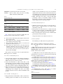
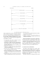
Microprocessors and Microsystems 26 (2002) 281–289
www.elsevier.com/locate/micpro
Bluetooth based home automation system
N. Sriskanthan*, F. Tan, A. Karande
School of Computer Engineering, Nanyang Technological University, Nanyang Avenue, Singapore, Singapore 639798
Received 17 September 2001; revised 8 May 2002; accepted 10 May 2002
Abstract
The past decade has seen significant advancement in the field of consumer electronics. Various ‘intelligent’ appliances such as cellular
phones, air-conditioners, home security devices, home theatres, etc. are set to realize the concept of a smart home. They have given rise to a
Personal Area Network in home environment, where all these appliances can be interconnected and monitored using a single controller. Busy
families and individuals with physical limitation represent an attractive market for home automation and networking. A wireless home
network that does not incur additional costs of wiring would be desirable. Bluetooth technology, which has emerged in late 1990s, is an ideal
solution for this purpose. This paper describes an application of Bluetooth technology in home automation and networking environment. It
proposes a network, which contains a remote, mobile host controller and several client modules (home appliances). The client modules
communicate with the host controller through Bluetooth devices. q 2002 Elsevier Science B.V. All rights reserved.
Keywords: Bluetooth technology; Microcontroller; Home automation; Wireless network
1. Introduction
The Bluetooth wireless technology is set to revolutionize
the way people perceive digital devices in our homes and
office environment. Now they are no longer just the
individual devices; instead, with the embedded Bluetooth
technology, they form a network in which appliances can
communicate with each other. This wireless technology is
especially useful in home environment, where there exists
hardly any infrastructure to interconnect intelligent appliances. It could be suitably used for home automation in a
cost-effective manner. Operating over unlicensed, universally available frequency of 2.4 GHz, it can link digital
devices within a range of 10 m (expandable to 100 m, by
increasing the transmitted power) at the speed of 1 Mbps.
Building upon this theme; we propose a home automation
system based on Bluetooth technology [1,2].
There are certain issues involved in the design of a home
automation system. The system should be scalable, so that
new device can easily be integrated into it. It should provide
a user-friendly interface on the host side, so that the devices
can be setup, monitored and controlled. The interface should
also provide some diagnostic services so those problems
* Corresponding author.
E-mail addresses: [email protected] (N. Sriskanthan), [email protected].
sg (F. Tan), [email protected] (A. Karande).
with the system, if any, can be tracked down. The overall
system should be fast enough to realize the true power of
wireless technology. It should also be cost effective in order
to justify its application in home automation.
The system developed during the course of this research
consists of a Host Controller (HC) implemented on a
Personal Computer (PC), and a microcontroller based
temperature-sensor/fan-controller, that is able to communicate with the host through the Bluetooth link. The system
is based on Home Automation Protocol (HAP), developed
by the authors in order to facilitate the master– slave
communication in a home automation network [3]. This
protocol ensures a prioritized, interlocked exchange of data.
It also supports dynamic addition and removal of devices on
the network. A user interface on the PC offers device
registration, control as well as diagnostic utilities. Bluetooth
development kit from Ericsson was used for the development [4]. A microcontroller was used as a device controller
for client modules [5,6].
The paper has been structured as follows. Section 2 of
this paper explains the HAP. Section 3 describes the salient
features of the user interface and PC to Bluetooth interface
for the host system. In Section 4, we present the temperature
sensor– fan controller circuitry and its interface to the
microcontroller through I2C lines. Section 5 discusses the
microcontroller to Bluetooth interface and the development
of a firmware for the microcontroller. Finally some
0141-933/02/$ - see front matter q 2002 Elsevier Science B.V. All rights reserved.
PII: S 0 1 4 1 - 9 3 3 1 ( 0 2 ) 0 0 0 3 9 - X
282
N. Sriskanthan et al. / Microprocessors and Microsystems 26 (2002) 281–289
Fig. 1. Bluetooth based home automation system. (a) Host and client modules in a Bluetooth piconet. (b) An individual client module.
recommendations regarding further research in this area are
discussed.
2. Home Automation Protocol
The Home Automation Protocol (HAP) facilitates the
communication among the host and client modules in a
home automation system. The communication covers the
device initialization process and the data transaction
process.
The protocol is constructed above Bluetooth software
stack [7]. It follows the layer model proposed by Bluetooth
Special Interest group (SIG). Considering the requirements
of home automation environment, the HAP has been based
on the core of the Bluetooth protocol architecture that
comprises of three stacks:
† Logical Link Control and Adaptation Protocol (L2CAP)
† Service Discovery Protocol (SDP)
† RFCOMM (serial cable emulation protocol) protocol.
HAP device initialization process uses the enhanced SDP
functionality to query device information and services.
L2CAP provides data services to the HAP with protocol
multiplexing capability, segmentation and reassembly oper-
ations. RFCOMM facilitates wireless communication and
provides transport capabilities for home automation services.
A typical Bluetooth based home automation system
includes a host and several client modules. Considering the
entrance price of the Bluetooth, it will be more cost effective
to have multiple Device Controllers (DC) connected to a
Bluetooth device. Each DC, in turn, monitors multiple
Attached Devices (AD) as shown in Fig. 1.
2.1. Home automation descriptor table
The host needs to store information regarding all the
active devices in the network. Similarly a DC needs to store
information pertaining to the devices directly attached to it.
The information is stored in the form of descriptors. The
formats of descriptors on the DC and the host are shown in
Tables 1 and 2, respectively.
Descriptor table terms explanation:
AD
the ID of the attached device
TOD
the type of Attached Device (I2C address)
I_SIZE
the instruction size in bytes for given device
D_SIZE
the data size in bytes for given device
D_NAME the device name, a NULL terminated string (32
bytes)
RW
the read and write access: Read Only ($00),
Write Only ($01), Read & Write ($02)
N. Sriskanthan et al. / Microprocessors and Microsystems 26 (2002) 281–289
PRIORITY the priority between the various ADs
STATUS there are three states for devices: Pending
($00), ACK ($01), NACK ($02)
Table 1
DC-side descriptor table
AD
Status
7-Bits
2-Bits
283
added or removed. If HC does not receive an acknowledgment from the DC, the host assumes that the DC is
not working properly or has been removed. The HC will
stop transferring any information to the AD of that DC.
2. When a DC finds a new AD or a removed AD while
performing a DCP, it sends DDP or DRP to the HC.
Depending on whether the HC acknowledges it or not,
the DC updates the local descriptor table.
2.2.3. Data transaction process
Table 2
Host-side descriptor table
TOD
I_SIZE þ D_SIZE
D_NAME
RW
Priority
7-Bits
2-Bits þ 3-bits
32-Bytes
2-Bits
7-Bits
2.2. Protocol description
Fig. 2 shows the process diagram for HAP. The four
indexed activities in the diagram are as follows:
(1) DC searches for all existing ADs and places them in the
DC descriptor table.
(2) HC searches for device information in DC database
and constructs the descriptor table.
(3) HC periodically checks the status of each DC and
requests it to check its devices.
(4) DC searches for all the devices and sends back the
feedback information. If new device is found, DC
sends the Device Detection Packet (DDP). If a device
is not found (removed), the DC sends the Device
Removal Packet (DRP).
The sequence of operations can be categorized into three
different processes as follows.
2.2.1. Device initialization process
1. On reset, the HC sends Device Checking Packet (DCP) to
each DC. A DC performs a scan on its ADs and sends a
DDP to the host for each device found.
2. If the AD information is found on the HC, it will
automatically pop up the window for device control. If
user acknowledges the device found, an ACKP would be
sent back to the DC, otherwise NACKP would be sent.
3. If the new AD is not stored in the HC, HC will pop up
window to request user to configure the new AD. If user
acknowledges and configures the device, the ACKP
would be sent back to the DC, otherwise NACKP would
be sent.
1. CMDP (Command packet) will be sent from the HC to a
DC in order to control the AD or to retrieve status
information of the AD.
2. If the packet received by the DC is to control an AD and
no data is required in return, an ACKP will be sent back
to the HC, after executing the necessary commands.
3. If the command packet requests for data, a DATAP (Data
packet) will be sent back to HC.
All packet formats are described in Section 2.3.
2.3. Packet formats
The following are abbreviations for packet format.
PIT packet type identifier to indicate the packet type
DC þ AD define the Device Controller and the Attached
Device
I_SIZE define the instruction size in bytes for given device
D_SIZE define the data size in bytes for given device
INSTRUCTION define the instruction contents
DATA define the data contents.
(1) DDP (Device Detection Packet). This packet is to
inform the host a new device is attached to the network and
need to be configured (Table 3).
(2) DRP (Device Removal Packet). This packet is to
inform the host that a device has been removed (Table 4).
(3) DCP (Device Checking Packet). This packet is to
inform a DC to send back an acknowledgement to the HC
and check the status of an AD (Table 5).
(4) ACK (Acknowledgement Packet) (Table 6).
(5) NACK (Non-Acknowledgement Packet) (Table 7).
(6) CMDP (Command packet). This packet is sent by the
HC to control the AD or request for AD status information
(Table 8).
(7) DATAP (Data packet). This packet is to transfer
device information back to the host (Table 9).
Table 3
Device detection packet
2.2.2. Periodic checking process
1. Host periodically sends the DCP to a DC to check if it is
working properly and whether any new AD has been
PIT
DC þ AD
$00
3-Bits þ 7-bits
284
N. Sriskanthan et al. / Microprocessors and Microsystems 26 (2002) 281–289
Fig. 2. Transformation process diagram of home automation system.
Table 4
Device removal packet
Table 7
Non-acknowledge packet
PIT
DC þ AD
PIT
DC
$01
3-Bits þ 7-bits
$B0
3-Bits þ 7-bits
Table 5
Device checking packet
Table 8
Command packet
PIT
DC
PIT
DC þ AD
I_SIZE þ D_SIZE
$10
3-Bits
$A0
3-Bits þ 7-bits
2-Bits þ 3-bits
Table 6
Acknowledgement packet
Instruction
Data
Table 9
Data packet
PIT
DC þ AD
PIT
DC þ AD
D_SIZE
$B1
3-Bits þ 7-bits
$A1
3-Bits þ 7-bits
3-Bits
Data
N. Sriskanthan et al. / Microprocessors and Microsystems 26 (2002) 281–289
285
to enter a set of new information and register as a new
device.
3. Bluetooth home automation PC software
The Bluetooth home automation PC software module is
the main Host Control Application (HCA) for other DCs.
The HCA provides three main services to the users, namely:
1. Device Registration
2. Diagnostics utility
3. Device Status and Control.
3.1. Device registration
The home automation system supports a Plug and Play
(PNP) methodology, which means a new device, can be
added readily to the system [8]. In order to handle dynamic
addition of new devices and to reduce the complexity of the
client software, a device database is stored on the HCA [9].
This device database holds information about each type
of device that is supported, similar to printer drivers in PC.
If a new device needs to be added, it could be registered
using the device registration utility. The database can be
considered as a driver for each of the client modules.
The information required to identify each device is the
following (Table 10).
The entire database is stored in the initialization file
located in the system’s Windows directory. The initialization file also contains other user settings required to
configure the serial port for communicating with the
Bluetooth Toolkit. The menu includes an Open File option,
which allows an initialization file to be loaded from disk.
Similarly, a Save File option would allow this file to be
saved in disk for backup purposes.
Upon startup of the program, a graphical user interface
(GUI) will be presented. The information of each registered
device would be added to a device list. When the user
selects the Registration Tab, this device list and information
on each selected registered device will be presented to the
user for selection.
After each device’s information is displayed, the user can
choose to edit the device information of the selected device
or to add a new device. If either of these options is chosen, a
new interface would be displayed in the same type which
allows the user to change the existing device information or
3.2. Diagnostics utility
The diagnostics utility provides the HC a means to test
essential Bluetooth communications with the DC connected
to it at the application level. It allows the user to connect the
HCA to the DC and send data to it. This utility is useful
during the development phase and also essential for
troubleshooting purposes. The access to the utility functions
are provided through a user friendly GUI.
Upon start up, the correct serial port as indicated in the
user setting menu would be connected at the specified baud
rate. The user settings menu will be saved in the
initialization file upon termination of the application.
After a connection to the specified serial port is made, the
user can perform diagnostic Bluetooth functions. The
Bluetooth functions provided on the HCA are the Reset,
Connect ACL (Asynchronous Connection-Less link) or
SCO (Synchronous Connection Oriented link), Disconnect,
Inquiry, Board Address and Send Data.
The sequence of operations for a normal data connection
from the HCA is highlighted in the sequence below:
1. Perform a Reset operation to initialize the Bluetooth.
2. Perform an Inquiry operation to search for all the
Bluetooth devices present on the piconet.
3. After obtaining a client Bluetooth address, a Connect
ACL operation to this address is required to setup the
connection for data transfer.
4. After the ACL connection is successful, data could be
entered in the data entry textbox and sent to the client
through the Send operation.
5. After all data are transferred, a Disconnect operation is
performed to terminate the Bluetooth connection.
3.3. Device Status and Control
The Device Status and Control application is the main
application to control and monitor ADs. In contrast to the
Diagnostics utility, which can also be used to obtain status
information about an AD and to control the device, the
Table 10
Device information stored in device database
Field name
Description
Device Type ID
Device Name
Read/Write Type
Priority
Instruction Size
Data Size
Uniquely define each type of device. Current system supports 128 devices. (7-bit AD)
Name of the device
Specifies whether the device is Read Only, Write Only or both
Specifies the priority level of the device
Specifies the size of each instruction
Specifies the size of the data
286
N. Sriskanthan et al. / Microprocessors and Microsystems 26 (2002) 281–289
Device Status And Control application does the same
functions at a hidden layer.
Using the GUI a list of ADs would be displayed for
Registration. When an AD is selected, the related device
information will be obtained from the connected device at a
hidden layer, which consists of ACL connections, data transfers
and disconnect operations. The data transfers and connection
operations are compliant with the protocol to synchronize the
transfer between the HC and a DC. In addition, the protocol
provides different packets to be sent for different purposes and
all these operations are performed at a hidden layer.
At this level the user is not concerned with the packet
formats and the protocol between HC and DC. Besides
obtaining the AD status, the user can also choose to control
the AD. When the user selects the AD and the control option
is selected, control values can be sent to the AD and
depending on the type of device, the DC will be able to use
these values to control the AD.
4. Hardware design and development
A temperature-sensor/fan-controller circuitry has been
developed to demonstrate the feasibility and effectiveness of
the application. The hardware interface component of the
Bluetooth based home automation system consists of a
Microcontroller –Transducer interface through I2C bus and
an RS232 link between the microcontroller and the Bluetooth. Thus the microcontroller acts as a DC and the
temperature-sensor/fan-controller IC act as ADs.
4.1. Microcontroller –Transducer interface
In order to minimize the cost of the overall system, it is
desirable to have multiple appliances connected to a single
Bluetooth, with one or more microcontrollers monitoring
them. I2C bus is a suitable choice for such a network of
appliances. I2C is the acronym for Inter-IC Connect bus,
which is a synchronous serial bus, developed primarily by
Philips Semiconductors [10,11]. Currently there are over
1000 devices that are registered as licensed components
with assigned addresses and various enhanced versions of
the I2C bus protocols have been introduced.
4.2. I2C protocol
The I2C bus is implemented using 2-wires to communicate data serially among devices. One line is called SCL
(Synchronous Clock) while the other one is known as SDA
(Synchronous data). Devices on the bus can either be in a
multi-master, single-master environment or in slave mode.
The master device generates the clock signals and initiates
the data transfer on the bus. Fig. 3 shows a typical operating
environment of the I2C bus where microcontroller A and B
can operate as master or slave while other peripherals
operate in slave mode only [12].
4.3. Room temperature control system
The system consists of a temperature sensing circuit,
which is used to track the room temperature and a fan
control circuit that is used to regulate the room temperature
as shown in Fig. 4.
The controller IC chosen incorporates a precise digital
thermometer to measure the temperature from a remote
sensor along with an on board fan controller [13,14].
The controller IC, from a programmer’s perspective,
looks like a set of byte-wide registers that contain
temperature data, alarm threshold values or control bits.
The WHI register determines the highest temperature limit
(THigh) that the temperature sensor can sense, while the
WLOW register give the lower temperature limit (TLow).
These values then can be adjusted easily to measure the
room temperature thereby increasing the resolution of the
measured temperature. The WCRIT register specifies
the critical over-temperature (TCrit) value for the system.
The RTEMP contains the latest temperature value provided
by the ADC after sensing the remote diode.
The ALERT interrupt is asserted when the value in the
RTEMP register exceeds the user-defined temperature range
specified by the values of THigh and TLow registers. In
response to this the microcontroller can be programmed to
instruct the Controller IC to do specific tasks viz. start the
fan. The OVERT interrupt is activated when the values in
the RTEMP register equals to or exceeds the TCrit value.
When this OVERT interrupt is asserted, the microcontroller
can be programmed to raise an alarm. The chip also has a
Fig. 3. Example of multi-master operating environment for the I2C bus [2].
N. Sriskanthan et al. / Microprocessors and Microsystems 26 (2002) 281–289
287
Fig. 4. Room temperature control circuit [14].
continuity fault detector which detects whether the remote
diode has an open-circuit condition or short-circuit
condition to GND. This diode fault will also assert the
ALERT interrupt.
This system simulates a room environment where the
user sets the range of temperature values for the room.
These values are then communicated to the DC after the
Bluetooth connection takes place. The DC then generates
the necessary commands via the I2C serial bus.
The DC continuously tracks the room temperature. If the
room temperature exceeds the THigh value, the DC will
instructs the Controller IC to start the fan in order to reduce
the temperature of the room. If TLow is less than or equal to
the preset value, the temperature can be raised using a
heater, which is currently out of the scope for this report. If
the room temperature exceeds the critical temperature, for
example when there is a fire in the room and the room
temperature raises, the DC raises an alarm, which is a safety
measure, provided by the system.
5. Software development
The firmware for the microcontroller was developed
using assembly and C language. The software module
controlling the Bluetooth includes: a set of instructions
necessary to initialize the Bluetooth device after power-onreset, configure it to identify itself on Bluetooth piconet,
accept the connection request from the host, establish the
connection, and handle the subsequent exchange of data.
The exact sequence of events after power-on-reset is given
in Fig. 5 [15].
Each of these processes involves sending/accepting a series
of bytes to/from the Bluetooth module through RS232
interface. These bytes are defined according to Bluetooth
L2CAP (Logical Link Control and Adaptation Protocol) packet
format; for example, L2CAP instructions start with byte 0 £ 01,
L2CAP data packets begin with byte 0 £ 02, etc. [4].
The significance of the processes shown in Fig. 5 is
explained below:
† Reset. It is an L2CAP instruction. This command resets
the Bluetooth module and is usually used after power-onreset.
† Scan. This L2CAP instruction sets the module in standby
scan mode. In this mode, a Bluetooth module waiting to
join the piconet can identify itself.
† Auto Accept. This instruction sets the module in auto
accept mode, in which it can readily accept the
connection request from the master as soon as it arrives.
After receiving each of these commands, the Bluetooth
module sends back an acknowledgment. Finally, after the
ACL (or SCO) connection is established, it sends a data
packet to the microcontroller. The packet contains the
information like the connection handle, board address of the
Master, etc.
Once the connection is established, it remains valid until
either the HC or the DC drops out. The DC then waits for a
command from the HC side. When DC receives a command
from its Bluetooth module, it extracts the actual HAP
instruction from the L2CAP envelope, identifies it, executes
it and sends either acknowledge or a data packet to
Bluetooth module for transmission.
Software based I2C bus controller module was developed
for microcontroller. It manipulates two I/O pins of the
microcontroller so that I2C protocol based communications
are carried out via the two of its pins.
The home automation, HCA software was run on the PC
acting as a host. The microcontroller programmed in the
288
N. Sriskanthan et al. / Microprocessors and Microsystems 26 (2002) 281–289
Fig. 5. Transformation diagram to establish ACL connection.
manner explained above acted as a DC. The system was
tested to ensure its conformance to the Home Automation
Protocol. A communication link was established between a
PC and the microcontroller through Bluetooth devices. The
host successfully controlled the temperature-sensor and fancontroller to a preset value. The steps used to implement and
test the HAP are as follows:
† The temperature sensor and fan controller is registered
on the PC and an AD address is provided
† Functionality to interpret and respond to the instruction
from the host is added to the microcontroller program.
This includes functions to read the temperature from the
AD and control the fan speed according to the
instructions from the host.
† Both the host and the DC are reset. After the ACL
connection is established, the HC requests the DC to
check for registered devices.
† The DC receives acknowledge from the temperature
sensor and responds positively to the host.
† Now, each time the DC receives a command, it checks
whether it is intended for it, and if it is, then it checks
which AD is to be handled from specific bit-fields in the
command.
† The host sends requests for temperature data. The DC
interprets the HAP instruction and executes the function
to access the sensor and read the temperature. It sends the
temperature data to the host.
† Similarly, it responds to the periodic checking commands from the host by accessing the AD (sensor) and
checking for acknowledge.
Thus, the functionality of the protocol is verified for a
network, which consists of a single DC. The HAP consists
of specific bit-fields to identify different DCs and the
corresponding ADs, therefore the system can be easily
extended to accommodate multiple DCs. Such system can
be tested, if multiple Bluetooth devices are available. The
HAP is independent of the lower level Bluetooth protocols,
is designed to work in a piconet of Bluetooth devices.
6. Conclusions and recommendations
The objective of this proposal was to develop a home
automation system based on Bluetooth wireless technology.
The result is the HAP, which allows the user to monitor and
control different appliances connected over a Bluetooth
network in home environment. The system has been
demonstrated to be functioning by developing a room
temperature control system.
The nature of this project is such that it provides a great
N. Sriskanthan et al. / Microprocessors and Microsystems 26 (2002) 281–289
scope for further developments. In this system, the error
detection and correction facility is only handled at the
Bluetooth level. Similar facility can be developed at the
application level. Also, some security measures to avoid
interference of neighboring home automation systems can
also be incorporated into the application. The functionality
of the HAP can be tested for a larger network, using multiple
Bluetooth devices. For this project, we have used I2C
interface between the DC and the ADs. One can explore the
possibility of a parallel interface for faster appliances, or
power line interface, etc. In our application one Bluetooth
module is associated with only one DC. However, one can
assess the viability of a multi-drop RS232 interface between
a Bluetooth module and DCs. Of course, in ideal situation,
each appliance will have its own Bluetooth module.
With the explosion Internet and related technologies, the
home system looks set to enter this arena. The home-office
concept that enables consumers to control their home
appliances via the Internet is also possible. With our home
system, which consists of the HC that usually takes a form of
PC, Internet connectivity can easily be established and control
be made available. Efforts in such direction will help realize a
truly wireless, fully automated home automation system.
289
[12] I2C Serial Bus Analyzer, N. Sriskanthan, Tan Sue Lim, IWNA’01,
Singapore, 2001, p. 106–114.
[13] Maxim Integrated Products, Max233 12V Line Driver Chip
Datasheet, 2000.
[14] Maxim Integrated Products, MAX1669 Fan controller and Remote
Temperature Sensor Datasheet, 2000.
[15] W. Stalling, Data and Computer Communications, Prentice Hall,
Englewood Cliffs, NJ, 1997.
Nadarajah Sriskanthan, Associate Professor, School of Computer Engineering,
Nanyang Technological University, Singapore. He received the BSc degree in
Electrical Engineering from the University
of London and the MSc degree in
Electronic Equipment Design from Cranfield Institute of Technology, UK. He
worked in various electronic industries in
UK from 1972–1978. From 1982–1984,
he was at Cranfield Institute of Technology as Research Officer. Since 1985, he
has been teaching Microprocessors and Computer Interfacing Techniques, Digital TV and Multimedia Systems Design at the Nanyang
Technological University. His research interests are in developing
computer interface hardware and software, particularly for the
application of Computer Graphics, Digital Video Broadcasting,
Multimedia Technology, Internet Based Training Systems, Bluetooth
and Multiprocessors
Acknowledgments
Authors like to acknowledge the contribution, to the
project by the following under graduate students: Miss He
Yuxiong, Mr Ranadive Rohan Suresh, Mr Teo Chee Beng,
from the School of Computer Engineering, Nanyang
Technological University.
References
[1] The official Bluetooth website from Bluetooth SIG www.Bluetooth.
com, Date viewed: March 21, 2001, Bluetooth Specification Version
1.1.
[2] Bluetooth Committee, Specifications of the Bluetooth System (Core),
December 1999, V1.0B.
[3] Home System Specification, EHS, 1997.
[4] Ericsson Mobile Communications AB, User Manual—Bluetooth PC
Reference Stack, 1543 VNX 2/901 184 Uen Version R1a, April 2000.
[5] I.S. McKenzie, The 8051 Microcontroller, Prentice Hall, Upper
Saddler River, NJ, 1999.
[6] Phillips Semiconductors, 87C51 8-bit Microcontroller Data Sheet,
1999.
[7] Bluetooth Committee, Profiles of the Bluetooth System (Profiles),
December 1999, V1.0B.
[8] J. Kelsey, Programming Plug and Play, Sam’s Publication, 1995.
[9] USB Design By Example, A Practical Guide of Building I/O Devices,
John Hyde, Wiley, New York, 1999.
[10] Philips Semiconductors, The I2C Bus Specification, Version 2.1,
January 2000.
[11] Philips Semiconductors, The I2C Bus and How to Use It (Including
Specification, Version 1.0), Technical Manual, 1997.
Forest Tan Su Lim is a Senior Tutor with the School of Computer
Engineering at the Nanyang Technological University (NTU),
Singapore. He received the B.A.Sc. degree in Computer Engineering
from NTU and his Diploma in Electronic and Computer Engineering
from Ngee Ann Polytechnic, Singapore. He has been lecturing in the
area of digital circuit and system, and computer peripherals. He worked
as a software engineer at Philips Singapore to implement a tuner test
system at the Tuner R&D laboratory during industrial attachment and a
software engineering in the Defence Science and Technological Agent
(DSTA) System and Computer Organisation (SCO) arm. His research
interest includes system integration design and application, digital
television decoding and home automation implementation.
Karande Advait is a third year honours
year student in Computer Engineering
course in the School of Computer Engineering, Nanyang Technological University. His interests are Microprocessors,
Bluetooth and Electronic Design.