1
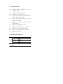
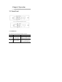
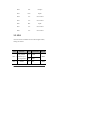
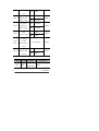
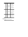
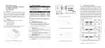
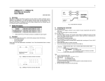
Media Converter
User Manual
Version: V4.1.2
Distance: MM: Multimode SM: Single-mode
□ 0~2km MM
□ 0~5km MM
□ 0~20km SM
□ 0~25km SM
□ 0~40km SM
□ 0~60km SM
□ 0~80km SM
□ 0~120km SM
Optical Port:
□ SC
□ FC
□ ST
Fiber:
□ Dual Fiber
□ Single Fiber
Converter type:
□InsidePower
□OutsidePower
□Module
Wavelength:
□ 850nm
□ 1300nm
□ 1310nm
□ 1550nm
Management:
□Yes
□ No
User Manual
2-16
Contents
Chapter 1 Introduction.......................... 4
1.1 Descriptions ........................................ 4
1.2 Characteristics ................................... 5
1.3 Technical Parameters ........................ 5
Chapter 2 Operation.............................. 9
2.1 Front Panel ......................................... 9
2.1.1 Indicators .................................. 9
2.1.2 Optical Port............................. 10
2.1.3 Ethernet port (NODE / HUB) . 10
2.2 SW1 ................................................... 11
Chapter 3 Installation.......................... 14
3.1 Installation........................................ 14
3.2 Troubleshooting................................ 15
User Manual
3-16
Chapter 1 Introduction
1.1 Descriptions
Media converter transmits IP over fiber, applied in
many places where need long distance transmission.
Enlarge the TP network range by MM or SM fiber. Low
consumption and high resistance to electromagnetic
interference of the optical fiber make the transmitting
distance spread from 100m to several decades KM or
hundred KM, improve the communication quality as well.
And make the server, repeaters, switch, terminal PC
connect easily. The user manual introduces Media
Converter characteristic, function, use and maintenance.
Please read the user manual carefully before installation.
User Manual
4-16
1.2 Characteristics
Supports
SNMP
management
(only
for
management device)
Selectable optical link-loss alarm
Selectable four transmitting modes
Comply with IEEE 802.3µ 100BASE-FX/TX,
IEEE802.3 10BASE-T, Standard
Comply with
IEEE
802.1Q VLAN
TAG,
full/half
duplex
Spanning Tree standard
Supports
10/100M,
auto-negotiation
Supports auto MDI/MDIX crossover
Supports transmission distance up to 120km
Same card on rack mounted and desktop
Supports over-sized packets up to 1600Bytes
Supports hot-swappable
1.3 Technical Parameters
Mechanical
Parameters
Size
21mm x 125mm x 165mm
Package
78mm x 170mm x 226mm
Work
-30~50
Storage
℃
-40~70℃
User Manual
5-16
220V AC /110V AC
Power
-48V DC/+24V DC
MM 2km OR MM 5km
Fiber
Output optical
power
Receiving
sensitivity
62.5/125, 50/125,100/140µm
>-18dBm
<-31dB
Distance
0~2km or 0~5km
Connector
SC, ST, FC
Wavelength
850nm/1300nm/1310nm
Optical Parameters
SM
Fiber
9/125, 8.3/125, 8.7/125 or
10/125µm
SM 20km
Distance
Output optical
power
Receiving
sensitivity
0~20km
>-15Bm
< -32dB
Connector
SC, ST, FC
Wavelength
1310nm
SM 25km
Distance
0~25km
User Manual
6-16
Output optical
power
Receiving
sensitivity
>-13dBm
< -32dB
Connector
SC, ST, FC
Wavelength
1310nm
SM 40km
Distance
Output optical
power
Receiving
sensitivity
0~40km
>-12dBm
< -33dB
Connector
SC, ST, FC
Wavelength
1310nm 1550nm
,
SM 60km
Distance
Output optical
power
Receiving
sensitivity
0~60km (when less than 15km,
use attenuator)
>-8dBm
< -34dB
Connector
SC, ST, FC
Wavelength
1310nm,1550nm
SM 80KM
User Manual
7-16
Distance
Output optical
power
Receiving
sensitivity
0~80km (when less than 15km,
use attenuator)
>-5dBm
< -36dB
Connector
SC, ST, FC
Wavelength
1550nm
SM 120KM
Distance
Output optical
power
Receiving
sensitivity
0~120km
(when
less
than
15km, use attenuator)
>-3dBm
< -38dB
Connector
SC, ST, FC
Wavelength
1550nm
User Manual
8-16
Chapter 2 Operation
2.1 Front Panel
Fig 1. Front panel of dual-fiber converter
Fig 2. Front panel of single-fiber converter
2.1.1 Indicators
Six indicators in the front panel of the converter:
Name
Definition
POW
Indicator of
power supply
FRX
optical interface
status indicator
Specification
ON when the power
supply is turned on and
in normal working status
Bright when optic fiber
cable is connected well,
but no data transmission
TRX
Ethernet
interface status
indicator
10/100
rate indicator
Blinking when receiving
data
Bright when twisted pair
is connected well, but no
data transmission
Blinking, when
receiving data
ON, 100M
OFF, 10M
FPL
Optical interface
signal detect
indicator
TPL
Ethernet
interface mode
indicator
ON, when detects the
optical signal
OFF, when no optical
signal detects
ON, Full duplex
OFF, Half duplex
2.1.2 Optical Port
RX: Optical signal output
TX: Optical signal input.
2.1.3 Ethernet port (NODE / HUB)
Supports auto MDI/MDIX crossover, the pin
definition of RJ-45:
Pin1
TX+
Output +
User Manual
10-16
Pin2
TX-
Output -
Pin3
RX+
Input +
Pin4
NC
Not connect
Pin5
NC
Not connect
Pin6
RX-
Input -
Pin7
NC
Not connect
Pin8
NC
Not connect
2.2 SW1
An 8 bits switch on Media Converter PCB signed “SW1”,
settings as follows:
NO.
Function
TP_FORCE
SW1-1
Status Specification
Default
ON Disable
OFF
Ethernet port
OFF Enable
auto-negotiation
SW1-2
SPEED
ON 10M
OFF
User Manual
11-16
Ethernet port
OFF 100M
rate
DUPLEX
SW1-3
SW1-4
ON Half duplex
OFF
Ethernet port
duplex mode
OFF Full duplex
FX_FULL
ON Half duplex
OFF
Optical port
OFF Full duplex
duplex mode
LFP
ON Enable
Link-loss detect
OFF Disable
SW1-5
OFF
D_WIRE
SW1-6
F_FWD
SW1-7
Transmission
See appendix
OFF
mode
X_EN
SW1-8
ON Nonsupport
OFF
Support IEEE
802.3X
OFF Support
Appendix:
D_WIRE F_FWD
OFF
OFF
Function
Storing and
transmitting
Description
Default
User Manual
12-16
mode
Determine the frontal
64K bytes of the
Modifying
OFF
ON
cut-through
mode
receiving data packet
whether to be stored
and transmitted.
Ethernet port should be
forced 100M at this
mode.
The receiving data
packet is not stored but
ON
OFF
cut-through
mode
directly transmitted.
Ethernet port should be
forced 100M, and the
packet delay is
minimum at this mode.
Adjust the transmitting
mode automatically
ON
ON
Auto mode
according to the rate of
the Ethernet port and
optical port.
NOTE:
Keeping SW1 default settings is suggested.
User Manual
13-16
Chapter 3 Installation
3.1 Installation
1)
After you received the devices, firstly you should
check whether the packing is well, otherwise,
please contact with our company or the local agent
in time so as to solve the problem.
2)
Turn on the power supply of the converter.
3)
Connect local RX to remote TX via optical fiber,
when local FPL indicator should be bright. And
connect local TX to remote RX, when both local
and remote FRX, FPL indicators should be bright.
If they are single-fiber converters, connect the
optical fiber, and it is OK.
4)
Turn on the power supply of the connected
Ethernet devices.
5)
Installation is completed.
NOTE:
Single-fiber bi-directional Media Converter has two
types:
Type A: Transmitting wavelength 1310nm, receiving
wavelength 1550nm.
Type B: Transmitting wavelength 1550nm, receiving
wavelength 1310nm.
Type A and Type B must be used in pair (i.e. if one
end is Type A, then the other end must be Type B)
3.2 Troubleshooting
Failure
Reasons
POW
Power
OFF
supply
Check
Troubleshooting
※Check whether
※Examine the
there is power
external power
input.
supply or
※Check whether
the power switch
turn on the
power switch
is turned on
FPL
OFF
Optical
port
fault
※Check whether
※Examine the
the fiber link is
fiber link
broken
※Check whether
※Correct the
connection
the optical
consumption is
over-size
※Check whether
User Manual
15-16
the connection is
correct
TRX
TP port
OFF
fault
※Check whether
※Examine the
the UTP is broken
UTP
the connection
rate
※Check whether
※Correct the
type is matched
※Check whether
the rate is matched
User Manual
16-16