1
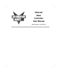
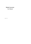
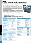
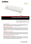
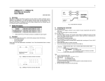
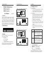
1 Overview, Checklist 2 IEEE802.3 10Mbps Ethernet TP-Fiber Converter TP-BNC Converter User's Manual Front and Rear Panel 10Mbps TP-to-Fiber Converter Front and Side Panel Et hernet Conv ert er 10B ase -T/FL (620-0012-000) IEEE802.3 10Mbps Ethernet supports various type media for network connection such as 10Base-2, 10Base-T and 10BaseFL. The media converter is used to convert one type media signal to other type equivalent that allows multiple type segments connect easily and inexpensively. The converters can be used as a standalone unit or as a slide-in module to the 19" converter rack(up to 10 units) for use at a central wiring closet. 2. Model Description Model Connector Type RJ-45 ↔ RJ-45 ↔ 820nm ST multi-mode BNC Installation 4. Installing the Converter 1. Overview TP-FL TP-BNC 3 10Mbps TP-to-BNC Converter Front and Side Panel E the rnet C onv erter 10B ase-T/ 2 For as a standalone unit: ⇒ Verify the AC-DC adapter conforms to your country AC power requirement and insert the power plug ⇒ Connect the media cable for network connection For as a slide-in unit: ⇒ The slide-in Media Converter and Converter Rack should be supplied only from the same source, both Media Converter and Rack are built to match on dimensions, DC jack, receptacle and power safety ⇒ Turn off the 19" converter rack power ⇒ Ensure that there is no activity in the network ⇒ Locate +5VDC power jack on converter back, carefully slide in and plug to 19" rack +5VDC power receptacle ⇒ Connect the media cable for network connection ⇒ Turn on the converter rack power, the Power LED will light up Fiber Port: TP Port: 3. Checklist Before you start installing the Converter, verify that the package contains the following: The Converter AC-DC Power Adapter This User's Manual T-Connector(for TP-BNC Converter model only) Please notify your sales representative immediately if any of the aforementioned items is missing or damaged. BNC BNC Port: Attach the fiber cable. The Tx, Rx fiber cable must be paired at both ends Attach UTP Cat. 3 or 5 cable to TP port MPR: To a Hub or Repeater DTE : To a workstation or NIC Slide switch "DTE" / "MPR" is on the side panel. Default: MPR Attach T-Connector to BNC port and connect the RG-58 coaxial network. Ensure the coaxial cable/segment is terminated at both ends properly Note: a. Use the straight-through cable. Cable pin-outs for RJ-45 jack 1, 2, 3, 6 to 1, 2, 3, 6 b. MPR(Default) : To a Hub or Repeater DTE : To a workstation or NIC (DTE pin-outs are crossover on board already) Configure the MPR-DTE slide switch on the side panel for cable connection to a Hub or NIC(Network interface Card). 4 NWay Device connection, LED Description 5. Connecting to 10/100Mbps NWay Device Converter Model TP-Fiber Converter TP-BNC Converter 10/100 NWay Inter-operating 10/100Mbps is auto-sensing and comes to 10Mbps Half-duplex 10/100Mbps is auto-sensing and comes to 10Mbps Half-duplex 6. LED Description TP-Fiber Converter: LED Color FL Green Link/Act TP Green Link/Act Collision Amber Power Green TP-BNC Converter: LED Color BNC Act Green TP Green Link/Act Collision Amber Power Green Function Lit when Fiber connection is good Blinks when any FL traffic is present Lit when TP cable connection is good Blinks when any TP traffic is present Blinks when any collision is present Lit when +5V power is coming up Function Blinks when BNC traffic is present Lit when TP connection is good Blinks when TP traffic is present Blinks when any collision is present Lit when +5V power is coming up 5 TP-Fiber Technical Specifications 6 7. TP-Fiber Technical Specifications • Standards : IEEE802.3 10Base-T/10Base-FL • TP Port : RJ-45 jack with a slide switch for "MPR" or "DTE" selection Fiber Port : The 10Mbps Fiber Transceiver: ST multi-mode 820nm Default • UTP Cable : Cat. 3 or 5 cable up to 100m Fiber Cable : 50/125, 62.5/125, or 100/140µm multi-mode 10Mbps Fiber Cable Limitations: Fiber Multi-mode: 2Km • Data Transfer Rate: 10Mbps at half-duplex • LED Indicators : FL Link/Act, TP Link/Act, Col, Power • Power Requirement : 1A@+5VDC • Ambient Temperature : 0° to 50°C • Humidity : 5% to 90% • Dimensions : 26.2(H) × 70.3(W) × 94(D) mm Note: Connecting to Router, Bridge, or Switch, please refer to the device's Technical Manual. TP-Fiber Technical Specifications 8. TP-BNC Technical Specifications • Standards : IEEE802.3 10Base-T/10Base-2 • TP Port : RJ-45 jack with a slide switch for "MPR" or "DTE" selection BNC Port : BNC connector • Cable and Distance : Cat. 3/5 unshielded or shielded twisted pair (UTP/STP) wire, maximum length 100 meters (328ft) 0.2 inch diameter RG-58A/U, 50Ω(ohm) coaxial cable, maximum length 185 meters(607ft) • Data Transfer Rate: 10Mbps at Half-duplex mode • LED Indicators : BNC/Act, TP Link/Act, Col, Power • Power Requirement : 1A@+5V • Ambient Temperature : 0° to 50°C • Humidity : 5% to 90% • Dimensions : 26.2(H) × 70.3(W) × 94 mm(D) 9. DC Power Jack and AC-DC Power Adapter The DC jack's central post is 2.5mm wide, it conforms to the DC receptacle(2.5mm) on the 19-inch Converter Rack slot. DC Jack 2.5mm DC Input: 1A@+5V Keep the AC-DC adapter as spare parts when Media converter is installed in a 19-inch Media Converter Rack. AC-DC power adapter AC Input : 100∼240VAC 50/60Hz DC Output: 1A@+5VDC