1
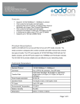
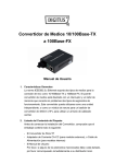
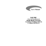
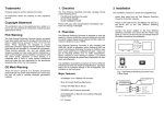
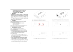
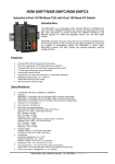
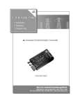
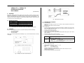
1
100Base-FX <> 100Base-TX
Fast Ethernet Converter
User’s Manual
(620-0062-000)
1.
Overview
2.
Model Description
IEEE 802.3u 100Mbps Fast Ethernet supports two types media for network connection such as
100Base-TX and 100Base-FX. The media converter is used to convert one type media signal to
other type equivalent that allows two type segments connect easily and inexpensively. The
converter can be used as a standalone unit or as a slide-in module to the 19” converter rack (up
to 10 units) for use at a central wiring closet.
Model
CFM3000
CFM3200
CFM3800C20/C40/C60
CFM3800C80/C100
*:
3.
Connector Type
Multi-Mode 1310nm Duplex-SC ↔ RJ-45
Multi-Mode 1310nm Duplex-ST ↔ RJ-45
Single-Mode 1310nm Duplex-SC ↔ RJ-45
Single-Mode 1550nm Duplex-SC ↔ RJ-45
Models with MT-RJ or VF-45 fiber connector are available only upon request!
Checklist
Before you start installing the Converter, verify that the package contains the following:
—
The TP-Fiber Converter
—
AC-DC Power Adapter
—
This User’s Manual
Please notify your sales representative immediately if any of the aforementioned items is missing
or damaged.
Fig. 3 Basic Network Connection
4.
Installing the Converter
For as a standalone unit:
⇒
Verify the AC-DC adapter conforms to your country AC power requirement and insert the
power plug
⇒
Connect the media cable for network connection
For as a slide-in unit:
⇒
The slide-in Media Converter and Converter Rack should be supplied only from the same
source, both Media Converter and Rack are built to match each other at dimensions, DC
jack, DC receptacle and power safety
⇒
Turn off the 19” converter rack power
⇒
Ensure that there is no activity in the network
⇒
Locate +5V DC power jack on converter back, carefully slide in and plug to 19” rack +5V DC
power receptacle
⇒
Connect the media cable for network connection
⇒
Turn on the converter rack power, the Power LED will light up
Fiber Port
TP Port
Fig. 1 100Mbps TP-to-Fiber Converter Front Panel
Fig. 2 100Mbps TP-to-Fiber Converter Side Panel
Attach the fiber cable. The Tx, Rx fiber cable must be paired at both
ends.
Attach TP Cat. 5 cable to TP port
MPR (Default) : To a Switch or Hub
DTE
: To a workstation or Network Interface Card (NIC)
“DTE”/”MPR” slide switch is on the side panel
Note:
a. Use the straight-through cable.
Cable pin-outs for RJ-45 jack 1, 2, 3, 6 to 1, 2, 3, 6
b. MPR (Default)
: To a Switch or Hub
DTE
: To a workstation or NIC
(DTE pin-outs is crossover on board already)
Configure the MPR-DTE slide switch on the side panel for cable connection to hub or
Network Interface Card (NIC)
c. Be sure the proper wiring and the Link LED status
2
5.
Connecting to 10/100Mbps N-Way Device
Converter
TP Port
Converter
Fiber Port
Default: 100Mbps auto-duplex-negotiation
a. Full-duplex for 10/100 N-Way partner
b. Half-duplex for non N-Way TP partner or Class II Hub
100Mbps and comes to:
a. Full-duplex for 100Fdx fiber link partner
b. Half-duplex for 100Hdx fiber link partner
8.
Keep the AC-DC adapter as spare parts
when Media Converter is installed in a
19-inch Media Converter Rack.
Note:
—
TP Partner must be set at 10/100 N-Way Auto-Negotiation for full duplex operation. When
connecting to non N-Way TP partner, it will come to 100/half-duplex operation
—
Fiber Link Partner should be set at full duplex mode
6.
LED Description
9.
•
•
LED
FX Tx
7.
Color
Green
FX Link
Green
TX Tx
Green
TX Link
Green
FDX
PWR
Green
Green
Function
Blink when fiber data is transmitting
Lit when fiber connection is good
Blink when fiber data is receiving
Blink when TP data is transmitting
Lit when TP connection is good
Blink when TP data is receiving
Lit when full-duplex mode is active
Lit when +5V power is coming up
Cable Connection Parameter
100Base-X network allows 512-bit time delay between any two node-stations in a collision domain.
The overall bit-time of TP/Fiber wires and devices must be within 512-bit in a segment. You may
use a switch to break up collision domain and extend the cabling distance.
•
TP Cable Limitations: Cat. 5 100m
•
Multi-Mode Converters Fiber Cable Limitations:
2km in Full-Duplex mode and 412m in Half-Duplex mode
•
Single-Mode Converters Fiber Cable Limitations (Full-Duplex ONLY):
CFM3800 Single-Mode Converter:
C20
:
20km
C40
:
40km
C60
:
60km
C80
:
80km
C100
:
100km
DC Jack and AC-DC Power Adapter
The DC jack’s central post is 2.5mm wide; it conforms to the DC receptacle (2.5mm) on the 19inch Converter Rack slot.
Technical Specifications
Standards: IEEE 802.3u 100Base-TX/FX
Models:
Model
Connector Type
Multi-Mode 1310nm Duplex-SC ↔ RJ-45
CFM3000
Multi-Mode 1310nm Duplex-ST ↔ RJ-45
CFM3200
Single-Mode 1310nm Duplex-SC ↔ RJ-45
CFM3800C20/C40/C60
Single-Mode 1550nm Duplex-SC ↔ RJ-45
CFM3800C80/C100
*:
Models with MT-RJ or VF-45 fiber connector are available only upon request!
•
UTP Cable: Category 5, up to 100m
•
Fiber Cable:
50/125, 62.5/125, or 100/140µm multi-mode, up to 2km
8.3/125, 8.7/125, 9/125, or 10/125µm single-mode, up to 20~100km (models depended)
•
LED Indicators: POWER, FX LNK, FX Tx, TX LNK, TX Tx, FDX
•
Data Transfer Rate:
100Mbps auto-duplex-negotiation
100Mbps for half-duplex mode
200Mbps for full-duplex mode
•
Power Requirement: 1A@+5V DC
•
Ambient Temperature: 0° to 50° C
•
Humidity: 5% to 90%
•
Dimensions: 26.2 x 70.3 x 94 mm (H x W x D)
•
Complies with FCC Part 15 Class A and CE Mark
Note: Connecting to Router, Bridge, or switch, please refer to the device’s Technical Manual.