1
i re
dsh
UNIVERSITY OF HERTFORDSHIRE
fo r
Faculty of Engineering & Information Science
ert
BACHELOR OF SCIENCE DEGREE IN
MULTIMEDIA TECHNOLOGY
fH
Project Report
Un
ive
rsit
yo
Big Dave’s Little Trains (A Virtual Control System for
a Model Railway)
David Herridge
April 2004
i re
dsh
Abstract
Currently, the Model Railway industry is a rather backward type of cottage
industry that needs bringing up to date. This project outlines a new method of
controlling a model railway that will bring this outdated industry a step closer
fo r
to working effectively in the 21st Century.
The experts consulted about this project (The Old Barn Model Craftsmen)
consider the output to be a useful tool in modelling and are keen to add it to
Un
ive
rsit
yo
fH
ert
their catalogue.
i re
Acknowledgement
There are a lot of people who contributed to this project in some way. First
dsh
and foremost I would like to thank my father for his tireless aid in helping me
i.
Obtain cheap parts for construction of the layout.
ii.
Being my main consultant at the Old Barn Model Craftsmen.
iii.
His tireless work in helping me both with the tedious and
fo r
troublesome electronics and his work on the scenery of the layout on which I
couldn’t have done without him.
Without his help this project would have been a complete failure.
ert
Secondly I would like to mention the other expert involved. These experts are
members of the Old Barn Model Craftsmen and are mentioned throughout the
project. The other member consulted was Mr. Brian Taylor, head of the
fH
company. He was also a valuable aid.
Next in line for a great deal of thanks is my project tutor, Professor Talib
Alukaidey. I would have had great difficulty with a lot of the software if it
hadn’t been for his help and timely emails. Whenever I had a problem, an
yo
email suggesting something always seemed to appear before I even asked
him. Finally, the man who wrote the original copy of the “lprout.exe” program
used in this project. I do not know who he is but without the program, the
Un
ive
rsit
project would not function.
Page
Section
1
i
i re
dsh
Contents
Abstract and Thanks
2
Contents
1
Information and Background
4
2
Aims and Objectives
6
3
7
4
9
5
13
6
15
7
17
8
18
9
23
10
27
11
ert
Design
Implementation
Time Plan
fH
Risk Assessment
Un
ive
Block Diagram
User manual
Costing
Further Work
12
Testing
13
Evaluation and Conclusion
rsit
29
Research
yo
28
fo r
3
i re
1. Introduction and background
dsh
This project was conceived to control a model railway from a computer,
something that had never been done before. This meant offering an easy and
effective way of controlling a physical layout through the computer.
To understand all the concepts used, first it is a good idea to know a little
fo r
about the background of the involved devices.
ert
The model railway
Railways themselves have been around for a long time and the nostalgia of
the steam railway has become widespread since its decline. There are full
fH
size railways in operation dedicated to the preservation of steam railway.
However, it is not practical to own one of these and have in the home unless
you are a billionaire. To this end, model railways appeared and flourished.
Today, large companies exist to offer toys for children and detailed replicas of
yo
all kinds of railways, not just steam engines. However, companies that build
model railway layouts tend to be still orientated around the classic style of
cottage industry. Although electronics are used in the layouts, the controls
rsit
are simple knobs and buttons. This can cause very complicated control
panels, especially for the bigger layouts. The layouts themselves tend to be
very detailed and very expensive, thus only enthusiasts or rich clients tend to
buy them. However, this does not stop the common man from having his own
Un
ive
layout. Companies such as Hornby offer affordable products to build your
own layout. They now also offer computer software to design it and tell you
everything you need to make it, which they can then supply.
There are several scales of railway used in the U.K. “N” gauge is the smallest
and it operates on a 9mm track. The scale of the engines is 1:148 (British) or
1:160 on the continent. This is approximately 2mm per foot in real life.
“Double O” gauge is next with a scale of 4mm per foot and a track gauge of
16.5mm. “O” gauge is getting bigger still with a scale of 7mm per foot. G
scale is the biggest used widely and this is mainly for garden railways.
i re
The Computer
dsh
This will not be a history lesson on the origins of the computer. This section
will explain a little about how computers have been used in a similar way to
this project.
The computer has many ports for sending and receiving information. The
fo r
keyboard plugs in to the computer and allows it to receive an input from the
outside world. The printer plugs in and acts as an output through either the
parallel port or the universal serial bus. The terms are computer jargon for
ert
defining what type of port to use. Input/output (or I/O) cards have been
around for a long time now and are used widely in industry as a conduit to
control machinery from the computer. There are many examples of this.
fH
Precision engineering uses computers to control machinery, the design is put
in and the computer then tells the machine how to make it. For the purposes
of this project, nothing so extravagant is required but the general principle is
yo
the same.
2. Aims and Objectives
rsit
Basic Aims and Objectives
This final year project is aimed to create a control system for a model railway
layout. It will enable the end user to set up and plan all of the routes of a train
Un
ive
both entering and leaving a station with a minimum of user input. The system
should also allow for control and movement of different trains with sections of
the track isolated. This would allow for changing the engine to pull the train or
for storing extra engines in sidings.
i re
dsh
Detailed Overview
To create this virtual model railway control system, first a physical layout
would be needed, primarily for testing and finally for demonstration of the
working project. This must be of a suitable size to balance cost, size and
fo r
complexity. This will be the first objective to complete. Once this is
completed, all electrical connections must be wired. The main elements used
will be relays and solenoids to change the points (known as point motors) and
ert
power for the locomotives that would actually run on the layout. This will most
likely consist of a mains powered transformer and rectifier to change the
mains voltage to a 12V dc variable output. Next comes the computer
fH
interface. The first problem to deal with is deciding which port to enter
through. Two way signals may be required – one from the physical track
telling the computer where trains are and how points are currently set, and,
one from the virtual railway inside the computer to the track to control the
yo
trains and to set the points correctly. The next problem is how to write the
software to perform the actual control. This is the greatest problem so far and
will have to be looked into to find the ideal method for control. Macromedia
rsit
Flash or Director would seem the most likely choice using the keyboard
interface as the link between the two devices. Key presses can tell the
computer everything that it needs to know about the layout and the L.E.D.s on
the keyboard show that the computer is capable of sending signals as well as
Un
ive
receiving. It may also be feasible to use the parallel (lpt) port of the computer.
This should be left open to consideration as well. With expansion on this and
research into keyboard architecture, a new device could be made to interface
the railway to the computer, using one of the previously mentioned programs
to control it.
i re
dsh
3. Research
To complete this project, a lot of research would have to be undertaken to
fo r
learn about the principles of the system.
ert
Physical Layout
The first place to look was in books that were borrowed from the experts. A
list of these can be found in the appendix (see appendix B 1.1). The second
fH
area of research would be consulting the experts at The Old Barn Model
Craftsmen.
yo
Virtual Layout
Due to the fact that this was a new idea, my experts were unable to provide
any assistance with this part of the project. This meant that the best source of
knowledge being the Internet. There was one book that was unavailable and
rsit
may have proved very useful in this project. It comes highly rated by many
people and may prove useful in further development of this project. It is
entitled “Controlling the Parallel Port” by Jan Axelson. However, as this was
Un
ive
not available, it was not used. Please see appendix B 1.2 for the list of
websites visited.
i re
dsh
4. Design
Physical model railway
It was necessary to create a small layout for use in the demonstration of this
fo r
project. To this end several considerations must be made. The layout
should be
i.
Realistic
ert
The layout should conform to standards used in real life so that it was an
accurate model representation rather than a toy.
ii.
Portable
fH
The layout must be of a suitable size and be robust enough to be transported
around. This is so that it can be brought in to university for use in the
demonstration.
iii.
Attractive to look at
yo
In order to make a good impression with all those looking at it, it must be
suitably decorated. First impressions are everything when presenting a
project.
iv.
Functional
rsit
There must be enough on the layout to demonstrate that the computer is
indeed capable of running it and also bigger layouts.
v.
Cost effective
Un
ive
A usual railway layout of the size required would cost around £1000 ready
built. Obviously labour would be a large part of this and as this was a project,
I would undertake the work. The parts would still amount to around £200 so
the best way to do it would be to sift through a professional companies thrown
out bits.
To this end the experts were contacted to find a realistic, suitable design. In
conjunction with them the design used was reached (see appendix fig. 1.1).
i re
dsh
Virtual model railway
After due consideration and research of what had been used as a control
interface previously with model railways, a graphical user interface based
upon a plan of the physical layout was decided on. This meant drawing out
fo r
the layout on the computer and then positioning buttons accordingly.
The first thing to do now this has been decided is to choose the package to
use. The two obvious choices that were available were Macromedia Flash
ert
and Macromedia Director. For this project Flash was chosen, but Director
would probably do just as well. A separate drawing package would be
needed to draw out the GUI and then the controls would be added in Flash.
fH
A separate piece of code would control the parallel port, activated by Flash’s
Action Script.
yo
Electronics
This is an extra part now that had to be considered. This project will not only
require a virtual and physical layout to be created, but also they would need to
be linked together by an electronic interface. The majority of this section was
rsit
taken out of a book. This is mentioned in Appendix A and it was probably the
most useful book used. It is “Wiring the Layout” by Jeff Geary. This book
offers circuit diagrams of everything needed for a layout to be controlled by a
Un
ive
discrete output from a device. This is something that the parallel port of a
computer can readily supply. This meant that the parallel port was the best
choice for the control of the system. This meant that the majority of the
design work was done for me in this book. The final drawings and the initial
ones taken out of the book can be located in Appendix D.1.1 and 1.2.
i re
dsh
5. Implementation
Physical Layout
The first thing to do was to build the physical layout. To do this, a baseboard
fo r
is needed. Fortunately, there was a spare one available already made. It had
been constructed by the experts for a job that never took place and was now
cluttering up their workshop. It soon disappeared into the workshop used for
ert
this project. A few modifications were made to make it the right size and a
join made in the middle to make it more portable (see Appendix C Fig1.1).
Now a baseboard was ready, it was time to lay the track. It is a good time to
fH
mention that the track plan was mainly designed around the size of the
available baseboard. Usually, a plan is made and the baseboard designed
around it. If money were no object then this project had unlimited monitory
resources then it would have been done in this way. However, as this was
yo
not the case the baseboard available dictated the design. Thus, track was
laid on the baseboard and the design used fitted the best (see Appendix C
Fig1.2).
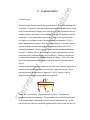
Once the track had been laid properly and pinned down, the next stage was to
rsit
add the “point motors” (basically 2 solenoids) to change the points. These
can also be seen at the bottom of Appendix C fig1.2. Below is FigA, a
Un
ive
diagram of how they are wired and how they operate.
FigA
There are 3 connections. The middle is the common. The other two
terminals are the live connection. They are either on or off and are switched
by the power supply, depending on which way the point has to fire. All the
points have the common connected together and the other wires are fed in to
i re
the control box. There a very large capacitor is used to “fire” the points. This
dsh
is called the capacitor discharge unit (CD or CDU).
Before moving on to the technical electronics side, it is good to talk about
what is seen on the layout. This was all added right at the end of the project
as time allowed. Appendix C fig1.3 to 1.6 shows a brief pictorial view of the
fo r
scenery and decoration being added. This is mainly artistic work and this
was mainly done either under instruction or by a third party, as it would be
very time consuming to an inexperienced artist.
ert
Back to the technical side now. With the majority of the layout done now,
there was the electronics to consider. As mentioned in the design work, the
drawings shown in Appendix D were taken straight out of the book. These
fH
were not quite what was needed for this project as they only offered 4 outputs
instead of the 16 needed. Also, the circuit could not be doubled up
completely as there was a limited availability of some of the expensive chips.
There were only binary decoders available with 4 inputs and outputs, not 8.
yo
This meant that 2 had to be used. As they are not aware where they are put
in the circuit, only certain higher numbers could be used. For example, 17
could not be used as pin 5 would be on and pin 1 would be on. These pins
are on different chips; thus the circuit would think there were 2 inputs. The
rsit
final circuit plan can be found in Appendix E. Appendix F shows all the
components needed to create the circuit, together with the price and RS
Un
ive
catalogue number.
The circuits were soldered by hand onto “veroboard” instead of proper printed
circuit boards (PCBs). This was because of the time and expense of
producing proper PCBs (There was no acid available). Once this was
completed, the power supply was mounted in a proper metal case to keep in
line with regulations when dealing with mains power and the rest of the
circuitry mounted in a convenient box.
Now would be a good time to mention the opto-isolators used in the circuit for
the computer output. These are special sealed chips that transfer the
information as light so as not to expose delicate equipment such as the
computer to high voltages should there be a problem with the circuit. These
i re
contain L.E.D.s (light emitting diodes) and a light receiver (not sure what,
dsh
probably an L.D.R. (light dependent resistor)).
The circuits used to control the layout from the computer are fairly complex
and take a lot of time to build, thus, in the mean time a small display unit is
useful to check outputs from the computer whilst constructing the software.
fo r
This can be made easily with 8 L.E.D.s and some wire. The one used in this
project was mounted in a box for convenience and this would be
recommended to ensure no short circuits. The L.E.D.s are connected via a D-
ert
type connector to the parallel port of the computer. The other pole is
connected to the ground output of the computer. This unit displays the binary
fH
output of the computer visually and can be used to test software.
Virtual Layout
There are two parts to the creation of the virtual layout. Basically, they are the
yo
easy part and the hard part. The easy part will be dealt with first. This is
creating the graphical user interface. The first thing to do here is to create a
scale drawing of the layout, preferably including all the scenery so the user
has an aesthetically pleasing but accurate view of what the physical layout
rsit
looks like. Any good design package is good for this, but for this project an
old program called “Designworks” was used. Macromedia Freehand or any
such program may be better as it is more up to date. Experience in the
Un
ive
program really dictates the choice of software to use and because of this,
Designworks was appropriate. Once this is done, the image must be
imported into flash to be used as a background. The next step is to insert
appropriate buttons. The minimum needed is 2 buttons for each point. As
well as this buttons to control the train are needed. “Go” and “stop” are
needed both in forward and reverse directions, meaning that another four
buttons are needed. Once these are in place they need to be configured
using ActionScript to perform the desired tasks. The ActionScript needed
sends the program to the frame u need as following:
i re
On(press) { gotoAndStop(2)}
dsh
This will send the movie to frame 2 and stop it when the button is pressed.
Now comes the second part of the virtual layout. This is the hard part. Firstly,
it is not possible to send or receive information from the parallel port in
JavaScript or VBScript, which are the 2 languages recognised by
fo r
ActionScript. It is necessary to run an external program. This can be done in
ActionScript as follows:
On(press) { fscommand(exec,”prrogram to run.exe”) }
ert
This is also not too tricky. The tricky part is to either find or write a program
that controls the parallel port. After extensive research in C, Java and C++, a
program was found written in Pascal that would suffice. It was a simple DOS
fH
based program that required a parameter in the command line. It is called
“LPTOUT.exe”. To send “1” to the parallel port “lptout 1” should be typed at
the command prompt. This meant that in the Windows operating system
several versions of the program must be made and the command line edited
yo
on each one to send a different signal to the port. This proved very tricky in
later operating systems and in the end Windows 95 or Windows 98 First
Edition proved to be ideal operating systems for running this project. These
older systems make a shortcut to the program that is run instead of the
rsit
original program through Windows. This means that it is possible to have
different programs sending different signals to the parallel port. The address
for downloading “LPTOUT” can be found in Appendix A, but is included here,
Un
ive
as it was such a vital piece of getting this project to work.
http://splat.foo.is/electronics/parallel_output.htm
http://splat.foo
Not only does this site have a ready to use compiled version of the program,
but it also has the code in Pascal, C, Assembler and Basic. These other
languages would work just as well, but then there is the problem of compiling.
Now all that is left to do is set up the shortcuts to the numbers required to
operate the physical layout (0 to 255).
i re
6. Time Plan
Time management is important to keep the work on schedule and meeting
dsh
deadlines. The plan below shows guidelines that should be met in order to
keep the project running smoothly without any of it being rushed.
fo r
Breakdown of Time plan
Due to several problems with the time plan, it could not be entirely stuck to.
This was mainly for 2 reasons. Firstly the problems with the software in
ert
getting the computer to send a signal to the parallel port and secondly with the
electronics as they didn’t quite work as predicted. The electronics will not be
mentioned in too much detail as the final schematic shows a working circuit
fH
after all the problems had been ironed out. However, the other problem was
that of finding the program for controlling the parallel port. The time plan did
not allow enough time for this and thus everything following the interface (after
week 26) was considerably put back. Most of the testing, in fact, was
yo
completed the day before the project demonstration. Fortunately, it all went
as planned and there were no problems then. However, it could have gone
completely the other way and the project would have been a failure. Perhaps
Un
ive
rsit
more research into the system would have been useful.
i re
Week 1 to week 3
Arrange title of project and sort out
dsh
formalities and details.
Week 4
Complete feasibility study
Week 5 and 6
Design plans for construction of
physical layout.
Start construction of layout, keeping
fo r
Week 7 and 8
well-documented reports of
progress for use in final report and
ert
seminar presentation.
Weeks 9 and 10
Start design of user interface for the
virtual layout in relation to the
fH
physical one.
Week 11
Prepare and present Seminar.
Week 11 to 18
Complete physical layout and begin
rsit
yo
work on interfacing the virtual and
Week 19 to 20
Un
ive
Week 21 to 26
Week 26 to demonstration deadline
After demonstration
physical layouts together.
Complete the virtual layout so that it
is a good representation of the
physical one.
Keep working on the interface,
prepare and present report to
external examiners.
Complete interface from virtual to
physical layout.
Testing and finishing touches,
user’s manual (scenery for layout –
aesthetics and preparation for
transport of layout for
demonstration)
Compile report from all information
gathered over the building of the
project.
i re
dsh
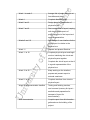
7. Risk Assessment
The main risk for this project is the bare rails of the physical layout of track.
When an engine is running, these rails will be live with a maximum 12V direct
fo r
current across them. Touching a rail whilst a train is in motion could result in
a small electric shock. There will also be moving parts in that the trains
themselves will move and the motors inside them will turn as well. These are
ert
ready built models that have passed a standard of safety. The electronics
were tested to ensure both functionality and safety. The final moving
component is the solenoid contained in the point motors. This is of minimum
fH
risk. Lastly, the risk of plugging the layout into a computer, there is little to no
risk here, as the device was fully tested prior to demonstration and was
Un
ive
rsit
yo
optically isolated from the computer.
Value of
Precautions
7
No one must touch
Acceptable as
current across
the physical layout
long as
physical train
except the project
precautions are
tracks.
demonstrator who
abided by.
fo r
12V direct
Acceptability
dsh
Risk (/10)
i re
Risk
has knowledge of
safe parts of the
Moving Trains
ert
track.
2
and other
Acceptable as
a safe distance
long as
from the physical
everyone
fH
moving parts.
Keep everyone at
Electronics and
connections to
3
Un
ive
rsit
the computer.
yo
layout.
stands back (or
stays seated).
Point motors
are negligible
risk.
This will initially be
Acceptable as
a risk to the test
long as all
computers,
testing is
however it will only
successful.
be tested on my
personal computer
to ensure the
safety of all
university systems.
When the project
is demonstrated
there will be little
to no risk.
i re
The highest level of risk is the voltage across the rails of the track. As long as
it is not touched by anyone other than the project demonstrator there is no
dsh
risk. There is no virtual risk with the software to be used.
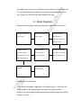
8. Block Diagram
fo r
Below is a block diagram showing the stages of construction of the layout.
Building of physical
track layout
track layout
fH
ert
Design of physical
operation of the
physical layout from
rsit
the virtual layout
physical computer
interface and
Design of computer
virtual and the
software for creating
physical layouts
the “virtual layout”
Documentation and
users manual
Un
ive
Debugging and
testing
and design for
Interfacing the
yo
Coding to allow
Circuit diagrams
Breakdown of Block Diagram
This is the block diagram suggested in the feasibility study. It was given as
rough guidelines, but these guidelines proved to be mostly accurate.
However, they were flexible in that sometimes more than one part was being
worked on at once.
i re
dsh
9. User Manual
The next 4 pages contain a standard user manual issued by the experts at the
Old Barn Model Craftsmen to all clients. It has been modified to
accommodate the layout used in this project and to use the unique control
fo r
system. There is technical information in there as well as just operating
instructions as it is important that the client is aware they have got what they
Un
ive
rsit
yo
fH
ert
paid for. This includes a specification of all that has been made.
i re
dsh
10. Costing
This project is not a cheap one to undertake, even doing everything “on the
cheap”, more money was spent than anticipated. The following few pages
offer a detailed pricing of:
How much the layout would have cost if built by the professionals
fo r
i.
using their system of pricing (Excel spreadsheet).
A sheet detailing the actual costs in building this, including all
second hand parts used.
iii.
ert
ii.
A components list of all the electronics and, where applicable, the
RS part codes and prices.
fH
It is clearly visible that if the project was to be undertaken again by another
Un
ive
rsit
yo
person that the costs would really mount up to well over £1000.
i re
dsh
11. Further Work
This project, although it fulfils all of the aims, is not entirely complete. Further
work would be to include sensing equipment on the track to:
i.
Relay back to the computer the position of the points, this will
fo r
show whether they have changed or not when they are supposed to and allow
for animation of them on screen in the virtual layout.
ii.
Show the position of the train. With well placed sensors the virtual
ert
layout could show the train going around the track just as it is on the physical
one. This will take a lot of coding and a lot of more complicated electronics,
but the results will really enhance the user’s experience.
fH
Finally, it would be nice to have route settings on the virtual layout. This was
originally the plan for this project, but, unfortunately, due to problems with
getting the computer to wait for the CDU to recharge, it was not possible to
accomplish. Route settings would get the points change one after the other to
yo
select a route automatically for the user. This would be very useful for bigger
Un
ive
rsit
layouts with lots of points.
i re
dsh
12. Testing
To ensure a stable system it must be tested. There were 2 stages of testing
used in this project. The first was to test the software and this used the box
with L.E.D.s to show the output from the parallel port in binary. This tests the
fo r
outputs from the program created in flash. When a button is pressed on the
GUI, this piece of apparatus displays the outputted result.
The second part of testing was with the entire project complete. This was to
ert
test that the layout responded properly to the incoming signals from the
computer. There were a few problems with this to be rectified. The first was
a simple one in that the trains were not running properly because the track
fH
was dirty (and second hand). This meant that the trains could not pick up
power from the rails effectively. This was resolved with a very fine grade of
sandpaper being gently rubbed over the rails.
The next problem was that the power was not really enough to get the trains
yo
moving at a decent speed. However, there is a pot in the speed control circuit
that can be used to adjust the top speed. This was turned up and this
resolved the problem.
Once these issues were resolved, the project worked as it should with no
Un
ive
rsit
problems.
i re
dsh
13. Evaluation and Conclusion
In all, this project was a success. It was a worthwhile undertaking as the end
result is a useful product rather than a useless piece of software that would
never be used again (a personal aim). There is room for further development,
fo r
but as a prototype it functions more than adequately. The software was not
quite what had been planned as it used stand alone programs to send the
signal to the parallel port. This meant that it was not as robust as it could
ert
have been. There was a lot more work on the electronics than previously
expected as well, meaning that a lot of time had to be spent both making the
circuits and debugging them once they were constructed. This was mainly
fH
due to a limited knowledge of electronics and not being able to find the exact
specification of the needed circuitry.
If this project were to be done again, then more time should have been
devoted to it. This may prove difficult as a final year project as many other
yo
subjects had to suffer when this was made due to the sheer mass of work.
However, the end results are well worth the hassle and work in undertaking it.
It is possible to conclude that the project was a complete success as it fulfilled
Un
ive
rsit
all of the aims and objectives.
Bibliography
The websites and books used are contained in Appendices A and B.