1
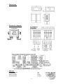
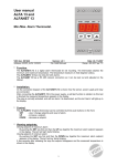
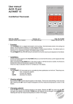
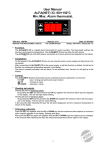
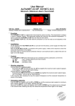
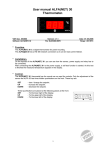
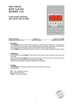
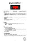
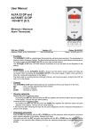
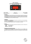
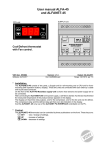
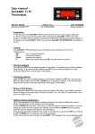
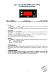
User manual ALFA(NET) 31 DP -10/+90OC Cool/Heat Thermostat. VDH doc. 091112 Software: ALFA(NET)31DP -10/+90C Version: v1.0 File: Do053809.wpd Date: 16-11-2009 Range: -10/+90C per 0,1C * Function. The ALFA(NET) 31 DP is a digital thermostat for panel mounting. The function from the thermostat can be programmed for cooling or heating. The ALFANET 31 DP has a RS 485 network connection so it can be read out and adjusted on the Alfanet. * Installation. On the topside of the ALFA(NET) 31 DP you can see how the sensor, power supply and relay have to be connected. After connecting the ALFA(NET) 31 DP to the power supply, a self test function is started. As this test is finished, the measured temperature appears in the display. When the relay is activated, the led 'on' will light-up in the display. * Control. The ALFA(NET) 31 DP thermostat can be controlled by three pushbuttons on the front. These keys are; SET - view / change the setpoint. UP - increase the setpoint. DOWN - decrease the setpoint. * Viewing setpoint. By pushing the SET key the setpoint appears in the display. The led 'set' starts blinking. A few seconds after releasing the SET key the setpoint disappears and the measured temperature is shown in the display. * Changing setpoint. Push the SET key and the setpoint appears in the display. Release the SET key. Now push the SET key again and together with the UP or DOWN keys the setpoint can be changed. A few seconds after releasing the keys the measured temperature shows again in the display. 1 * Setting internal parameters. Next to the adjustment of the setpoint, some internal settings are possible like differential, sensoroffset, setpoint range and the function cooling or heating. By pushing the DOWN key for more than 10 seconds, you enter the 'internal programming menu'. In the left display the upper and lower segment, are blinking. With the UP and DOWN keys the required parameter can be selected (see the parameter table). If the required parameter is selected, the value can be read-out by pushing the SET key. Pushing the UP or DOWN keys, together with the SET key allows you to change the value of this parameter. If no key is pushed for 20 seconds, the ALFA(NET) 31 DP changes to its normal operation mode. * Adjustment sensor. The sensor can be adjusted by using the Sensor Offset (parameter 04). Indicates the ALFA(NET) 31 DP e.g. 2C too much, the Sensor Offset has to de decreased by 2C. * Error messages. In the display of the ALFA(NET) 31 DP the following error messages can appear: Er - Sensor broken. Solution: - Check if the sensor is connected correctly. - Check the sensor (1000 at 25C). - Replace the sensor. EE - Settings are lost. Solution: - Reprogram the settings. * Technical details. Model : ALFA(NET) 31 DP Range : -10/+40C, readout per 0,1C Supply : 230Vac 50/60Hz (or else see productsticker), 3VA Relay : SPDT 250V/16A(C-NO), 8A(C-NC) (cos phi=1) Communication: RS 485 Network (2xtwisted pair shielded) only at ALFANET model. Control : by pushbuttons on the front. Front : Polycarbonate IP65 Sensor : SM 811/2m (1000 at 25C) Sizes : 35 x 77 x 71,5mm (hwd) Panel hole : 28 x 70mm (hw) - Provided with memory protection during power failure. - Connection with screw terminals on the back side. - Equipped with self test function and sensor failure detection. - Special versions are available upon request. 2 * Parameters ALFA(NET) 31 DP. PARAMETER DESCRIPTION PARAMETER RANGE 01 02 03 04 Switching differential Minimum setpoint Maximum setpoint Offset temperature sensor 1..15C -10..+40C -10..+40C -15..+15C 10 11 Startup delay after power failure Relays on at sensor failure 0..99 Minutes 0 = No 1 = Yes 0 0 15 Function cooling or heating 0 16 17 18 Switch on delay relays Switch off delay relays Parameter 16/17 in seconds or minutes 19 20 Minimum on-time relays Minimum off-time relays 0 = Cool 1 = Heat 0..99 0..99 0 = Seconds 1 = Minutes 0..99 Minutes 0..99 Minutes 90 95 96 97 98 99 Network number Software version Production year Production week Serial number (x1000) Serial number (units) 1..250 0..255 00..99 1..52 0..255 0..999 1 - 1) On active delay led 'on' blinks. * Function Diagram. 3 1) 1) STANDARD VALUE 3 -10 +40 0 0 0 0 0 0 * Dimensions. * Connection diagram. If applicable * Address. VDH Products BV Produktieweg 1 9301 ZS Roden The Netherlands Tel: Fax: Email: Internet: 4 +31 (0)50 - 30 28 900 +31 (0)50 - 30 28 980 [email protected] www.vdhproducts.nl