1
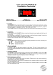
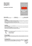
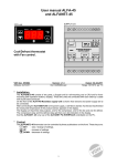
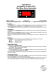
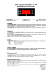
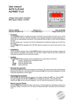
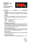
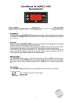
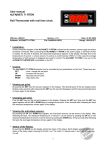
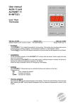
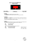
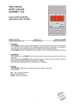
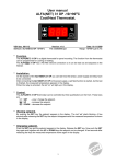
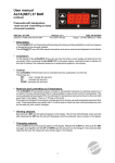
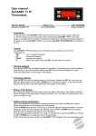
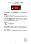
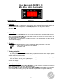
User Manual ALFA(NET) 33
Min./Max. Alarm thermostat.
VDH doc. 053810
Software: ALFA(NET) 33
Version: v1.3
File: Do053810.wpd
Date: 19-06-2012
Range: -50/+50/C, readout per 1/C
* Function.
The ALFA(NET) 33 is a digital alarm thermostat for panel mounting. The thermostat watches the
minimum and maximum temperature. The ALFA(NET) 33 has one relay for both alarms.
The ALFANET 33 has a RS 485 network connection so it can be read out and adjusted on the
ALFANET.
* Installation.
On the topside of the ALFA(NET) 33 you can see how the sensor, power supply and relay have to be
connected.
After connecting the ALFA(NET) 33 to the power supply,, it takes a few seconds to show the
measured temperature in the display.
The alarm relay is a multi functional combined minimum- and maximum-alarm, at alarm the LED
‘alarm’ is lit in the display.
* Control.
The ALFA(NET) 33 alarm thermostat can be controlled by three pushbuttons on the front;
SET
- view / change setpoints and reset of alarm.
UP
- increase a value.
DOWN - decrease a value.
* Viewing setpoints.
Viewing setpoint of maximum alarm:
By pushing the SET key first and then the UP key together the maximum alarm setpoint appears
in the display. The led 'set high' starts blinking.
Viewing setpoint of minimum alarm:
By pushing the SET key first and then the DOWN key together the maximum alarm setpoint appears in the display. The led 'set low' starts blinking.
A few seconds after releasing the keys the setpoint disappears and the measured temperature is
shown in the display.
* Changing setpoints.
Push the SET key together with the UP or DOWN key and the maximum alarm setpoint or minimum
alarm setpoint appears in the display. Release both keys.
Now push the SET key again and together with the UP or DOWN keys the setpoint can be changed.
A few seconds after releasing the keys the measured temperature shows again in the display.
1
* Actions of the alarm functions.
This alarm thermostat has two adjustable alarms namely, a minimum and a maximum alarm. Whereby
can be chosen from watch or control alarms (Parameter 27):
- Watch Alarm:
The relay is normally activated and LED ‘alarm’ is off. At alarm the relay is
deactivated and the LED ‘alarm’ is lit. This is also the case at power failure.
- Control Alarm: The relay is normally deactivated and the LED ‘alarm’ is off. At alarm the relay is
activated and the LED ‘alarm’ is lit.
Furthermore, an alarm can be hold or reset automatically (parameter 28).
- If alarms are hold (default), the alarms must be confirmed by pressing the SET button. Only when
the alarm cause is solved and the alarm is confirmed, the relay is set to its normal position.
- If alarms are not hold and the alarm cause is solved, the alarm will automatically reset and the relay
is set to its normal position.
Also, an offset (zone) and the differential for each alarm can be set. See the function diagram.
Furthermore, a delay time (Parameter 23 and 24) for each alarm can be set, during the delay time the
led ‘alarm’ flashes. If after ending the delay-time the alarm is still present, an alarm is given and the
relay is set into the alarm position. If the temperature is recovered within the delay time, than there will
be no alarm.
In the display is continuously shown H at maximum alarm and L at minimum alarm. Once the alarms
are confirmed, the measured temperature is shown again alternating with any outstanding actual alarm
indications.
* Sensor adjustment.
The sensor can be adjusted by using the Sensor Offset (parameter 04). Indicates the ALFA(NET) 33
e.g. 2/C too much, the Sensor Offset has to de decreased by 2/C.
* Error messages.
In the display of the ALFA(NET) 33 the following error messages can appear:
Er
- Sensor broken. Solution:
- Check if the sensor is connected correctly.
- Check the sensor (1000S at 25/C).
- Replace the sensor.
EE
- Settings are lost. Solution:
- Re programme the settings.
* Setting internal parameters.
Next to the adjustment of the setpoints, some internal settings are possible like differentials, sensoroffset, setpoint range and alarm settings.
By pushing the DOWN key more than 10 seconds, you enter the 'internal programming menu'. In the
left display the upper- and lower-segment are blinking. With the UP and DOWN keys the required
parameter can be selected (see the parameter table).
If the required parameter is selected, the value can be read-out by pushing the SET key. Pushing the
UP or DOWN keys, allows you to change the value of this parameter.
If no key is pushed for 20 seconds, the ALFA(NET) 33 changes to it's normal operation mode.
2
* Parameters ALFA(NET) 33.
PARAMETER
DESCRIPTION PARAMETER
RANGE
02
03
04
Minimum setpoint
Maximum setpoint
Offset temperature sensor
-50..+50/C
-50..+50/C
-15..+15/C
10
11
Startup delay after power failure
Relay on at sensor failure
0..99 Minutes
0 = No, 1 = Yes
0
0
21
22
23
24
25
26
Differential maximum alarm
Differential minimum alarm
Time delay maximum alarm
Time delay minimum alarm
Offset maximum alarm
Offset minimum alarm
1..15/C
1..15/C
0..99 Minutes
0..99 Minutes
0..+20/C
-20..0/C
1
1
0
0
0
0
27
Relay alarm function
(0=watchdog alarm 1=regulated alarm)
Auto reset alarm after temp. recovering
(0=hold alarm, 1=don’t hold alarm)
0..1
0
0 = No, 1 = Yes
0
90
Network number
1..250
1
95
96
97
98
99
Software version
Production year
Production week
Serial number (x1000)
Serial number (units)
0..255
00..99
1..52
0..255
0..999
-
28
(sensor calibration)
(only at ALFANET)
DEFAULT
VALUE
-50
+50
0
* Function diagram.
* Technical data.
Type
Range
Supply
Relay
Communication
Control
Front
Sensor
Dimensions
Panel cut-out
: ALFA(NET) 33 alarm thermostat
: -50/+50/C, readout per 1/C
: 230 Vac 50/60Hz 1,1VA
(or else see product sticker)
: 1x SPDT contact
Max. 250V/16A(C-NO), 8A(C-NC) at cos phi=1
: RS 485 Network (2x twisted-pair shielded) only at ALFANET model.
: thru pushbuttons on front.
: Polycarbonate IP65
: SM 811 2-wire PTC sensor (1000S at 25/C)
: 35 x 77 x 71,5mm (hwd)
: 28 x 70mm (hw)
- Provided with memory protection during power failure.
- Connection with screw terminals on the backside.
- Equipped with self test function and sensor failure detection.
- Special version are available upon request.
3
* Dimensions.
* Connection diagram.
If applicable
* Address.
VDH Products BV
Produktieweg 1
9301 ZS Roden
The Netherlands
Tel:
Fax:
Email:
Internet:
4
+31 (0)50 - 30 28 900
+31 (0)50 - 30 28 980
[email protected]
www.vdhproducts.nl