1
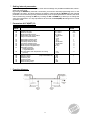
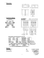
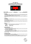
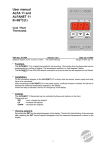
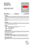
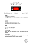
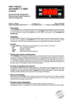
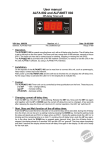
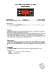
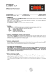
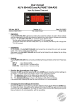
User Manual ALFA(NET) 33 -50/+150C Min./Max. Alarm thermostat. VDH doc. 100794 Software: 072760 ALFA(NET) 13/23/33 Version: v1.0 File: Do100794.wpd Date: 27-09-2010 Range: -50/+150C, readout per 1C * Function. The ALFA(NET) 33 is a digital alarm thermostat for panel mounting. The thermostat watches the minimum and maximum temperature. The ALFA(NET) 33 has one relay for both alarms. The ALFANET 33 has a RS 485 network connection so it can be read out and adjusted on the Alfanet. * Installation. On the topside of the ALFA(NET) 33 you can see how the sensor, power supply and relay have to be connected. After connecting the ALFA(NET) 33 to the power supply, a self test function is started. As this test is finished, the measured temperature appears in the display. The relay is normally activated, with an alarm it’s not activated, then the led 'on' will light-up in the display. * Control. The ALFA(NET) 33 alarm thermostat can be controlled by three pushbuttons on the front; SET - view / change set points and reset of alarm. UP - increase a value. DOWN - decrease a value. * Viewing set points. Viewing set point of maximum alarm: By pushing the SET key first and then the UP key together the maximum alarm set point appears in the display. The led 'set high' starts blinking. Viewing set point of minimum alarm: By pushing the SET key first and then the DOWN key together the maximum alarm set point appears in the display. The led 'set low' starts blinking. A few seconds after releasing the keys the set point disappears and the measured temperature is shown in the display. * Changing setpoints. Push the SET key together with the UP or DOWN key and the maximum alarm setpoint or minimum alarm setpoint appears in the display. Release both keys. Now push the SET key again and together with the UP or DOWN keys the setpoint can be changed. A few seconds after releasing the keys the measured temperature shows again in the display. 1 * Actions of the alarm functions. The ALFA(NET) 33 alarm thermostat has a minimum alarm and a maximum alarm both with there own setpoint. We can choose two different kinds of alarms (PARAMETER 27) namely: watchdog alarm relay normally activated, with alarm it falls off and the led 'alarm' burns. So on power failure the alarm relay also falls off. or a regulated alarm relay normally not activated, with alarm the relay will be activated and the led 'alarm' will burn. With PARAMETER 28 we can choose auto reset alarm or a hold alarm, after temperature recovering. Also it is possible to give both set points their own offset and differential see function diagram. Each alarm can be set at an alarm-delay time (PARAMETER 23 and 24) when the temperature will give an alarm the led 'alarm' first starts to blink. If the temperature will recover within the delay time, no alarm occurs. If an alarm will come through after the delay time the led 'alarm' burns continuously and the display alternates between the temperature and 'H' for high-alarm (max.) or 'L' for low-alarm (min.) to indicate the alarm. To reset an alarm, press the SET key. * Sensor adjustment. The sensor can be adjusted by using the Sensor Offset (parameter 04). Indicates the ALFA(NET) 33 e.g. 2C too much, the Sensor Offset has to de decreased by 2C. * Error messages. In the display of the ALFA(NET) 33 the following error messages can appear: E1 - Sensor broken. Solution: - Check if the sensor is connected correctly. - Check the sensor (1000 at 25C). - Replace the sensor. EE - Settings are lost. Solution: - Re programme the settings. -L- In case of sensor short-circuit the display alternates between error-code E1 and -L-, as indication for a short-circuit sensor. -H- In case of open-circuit sensor the display alternates between error-code E1 and -H-, as indication for a open circuit sensor. * Technical data. Type : ALFA(NET) 33 alarm thermostat Range : -50/+150C, readout per 1C Supply : 230 Vac 50/60Hz (3VA) or else see product sticker Relay : SPDT 250V/16A(C-NO), 8A(C-NC) (cos phi=1) Communication: RS 485 Network (2xtwisted pair shielded) only at ALFANET model. Control : thru pushbuttons on front. Front : Polycarbonate IP65 Sensor : SM 811 (2-wire PTC 1KOhm at 25C) Dimensions : 35 x 77 x 71,5mm (hwd) Panel cut-out : 28 x 70mm (hw) - Provided with memory protection during power failure. - Connection with screw terminals on the backside. - Equipped with self test function and sensor failure detection. - Special version are available upon request. 2 * Setting internal parameters. Next to the adjustment of the set point, some internal settings are possible like differential, sensoroffset, set point range. By pushing the DOWN key more than 10 seconds, you enter the 'internal programming menu'. In the left display the upper- and lower-segment are blinking. With the UP and DOWN keys the required parameter can be selected (see the parameter table). If the required parameter is selected, the value can be read-out by pushing the SET key. Pushing the UP or DOWN keys, allows you to change the value of this parameter. If no key is pushed for 20 seconds, the ALFA(NET) 33 changes to it's normal operation mode. * Parameters ALFA(NET) 33. PARAMETER DESCRIPTION PARAMETER RANGE 02 03 04 10 11 Minimum set point Maximum set point Offset temperature sensor Startup delay after power failure Relay on at sensor failure 21 22 23 24 25 26 27 Differential maximum alarm Differential minimum alarm Time delay maximum alarm Time delay minimum alarm Offset set point High (Maximum) Offset set point Low (Minimum) Relay alarm function 0=watchdog alarm 1=regulated alarm Auto reset alarm after temperature recovering (0=hold) -50..+150C -50..+150C -15..+15C 0..99 Minutes 0 = No 1 = Yes 1..15C 1..15C 0..99 Minutes 0..99 Minutes 0..+20C -20..0C 0..1 28 90 95 96 97 98 99 Network number Software version Production year Production week Serial number (x1000) Serial number (units) (only at ALFANET 33) * Function diagram. 3 DEFAULT VALUE -50 +150 0 0 0 1 1 0 0 0 0 0 0 = No 1 = Yes 0 1..250 0..255 00..99 1..52 0..255 0..999 1 - * Dimensions. * Connection diagram. If applicable * Address. VDH Products BV Produktieweg 1 9301 ZS Roden The Netherlands Tel: Fax: Email: Internet: 4 +31 (0)50 - 30 28 900 +31 (0)50 - 30 28 980 [email protected] www.vdhproducts.nl