1
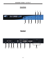
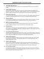
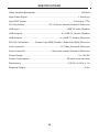
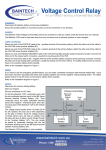
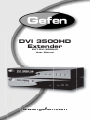
DVI 3500HD
Extender
EXT-DVI-3500HD
User Manual
www.gefen.com
f
ASKING FOR ASSISTANCE
Technical Support:
Telephone
Fax
(818) 772-9100
(800) 545-6900
(818) 772-9120
Technical Support Hours:
8:00 AM to 5:00 PM Monday thru Friday.
Write To:
Gefen Inc.
c/o Customer Service
20600 Nordhoff St
Chatsworth, CA 91311
www.gefen.com
[email protected]
Notice
Gefen Inc. reserves the right to make changes in the hardware, packaging and
any accompanying documentation without prior written notice.
DVI 3500HD is a trademark of Gefen Inc.
© 2009 Gefen Inc., All Rights Reserved
All trademarks are the property of their respective companies
Rev A
CONTENTS
1
Introduction
2
Operation Notes
3
Features
4
Sender Panel Layout
5
Sender Panel Descriptions
6
Sender Panel Descriptions
8
Receiver Panel Layout
9
Receiver Panel Descriptions
10 Receiver Panel Descriptions
11 Connecting And Operating The DVI 3500HD
12 Connecting And Operating The DVI 3500HD
13 Local And Virtual DDC Modes
14 Switching Active USB Control
15 Specifications
16 Warranty
INTRODUCTION
Congratulations on your purchase of the DVI 3500HD. Your complete satisfaction
is very important to us.
Gefen
Gefen delivers innovative, progressive computer and electronics add-on solutions
that harness integration, extension, distribution and conversion technologies.
Gefen’s reliable, plug-and-play products supplement cross-platform computer
systems, professional audio/video environments and HDTV systems of all sizes
with hard-working solutions that are easy to implement and simple to operate.
The Gefen DVI 3500HD
The DVI 3500HD allows you to operate a single DVI-compliant computer at two
physical locations. DVI, USB, analog audio, and RS-232 are extended from the
local computer to the remote workstation. USB peripherals can be operated by
the computer at either location exclusively.
How It Works
The DVI 3500HD system consists of a Sender and a Receiver unit. The Sender
connects to the computer’s DVI-compliant video card output, analog audio jack,
RS-232 port, and USB port. The DVI 3500HD Receiver connects to the remote
display and peripherals. Four strands of LC fiber optic cable connect the Sender
and Receiver together.
The DVI 3500HD has two modes of USB operation. When in local mode, the
computer sees USB devices connected to the Sender. When in remote mode,
the computer sees USB devices connected to the Receiver. Modes are switched
using a switch on the front panel of the Sender.
1
OPERATION NOTES
READ THESE NOTES BEFORE INSTALLING OR
OPERATING THE DVI 3500HD
•
LC terminated fiber optic cables (2 pairs) are required for operation of the
DVI 3500HD system.
•
The DVI 3500HD relies on either Virtual DDC or a locally connected display
(on the sender unit) for display information (EDID). In Virtual DDC mode
the sender unit will store the remotely connected display’s EDID. This
EDID will need to be recorded onto the sender unit. Please see page 13 for
instructions on using the Virtual DDC feature.
•
When using a local display please ensure that the remote display can
display common resolutions and timings that are in the EDID of the local
display. The reverse applies when using the Virtual DDC mode. The local
display in Virtual DDC mode must be able to accept common resolutions and
timings that are in the EDID of the remote display.
•
This device will accept both Single-Mode and Multi-Mode fiber optic cables.
•
This device will accept both 50μ and 62.5μ multi-mode fiber optic cable
types.
•
Maximum extension with Single-Mode fiber optic cable is 6,560 feet (2
kilometers) at a maximum resolution of WUXGA (1920x1200/60Hz)
•
Maximum extension with Multi-Mode fiber optic cable is 1,640 feet (500
meters) at a maximum resolution of WUXGA (1920x1200/60Hz)
•
WARNING: Do not look directly into LC receptacles of the sending unit. This
device, however, does operate under the Laser Class I specification for eye
safety.
2
FEATURES
Features
•
Extends any DVI compliant computer up to 6,600 feet (2 km)
•
Uses 4-strand multimode LC fiber cable
•
Supports computer resolutions up to 1920x1200@60 Hz
•
Supports DDWG standards for DVI compliant monitors
•
Supports Virtual DDC and DDC2B protocols
Package Includes
(1) DVI 3500HD Sender
(1) DVI 3500HD Receiver
(2) 12V Power Supply
(1) 6 ft USB Cable (A-B)
(1) 6 ft DVI-DL Cable (M-M)
(1) 6 ft DB-9 RS-232 Cable (M-F)
(1) User’s Manual
3
SENDER PANEL LAYOUT
Front Panel
4
5
6
1
2
3
7
8
9
Back Panel
10
11
12 13
14
15
16
4
17
18
SENDER PANEL DESCRIPTIONS
1
Self-EDID LED Indicator
This LED indicator will be used when recording the EDID for the Virtual DDC
mode.
2
Optic B LED Indicator
This LED will indicate the status of the connection between the sender and
receiver’s 2 pair of LC fiber optic cables labeled Optic B. This LED will be active
when a valid link between the sender and receiver has been established.
3
Power LED Indicator
This LED will become active once the included 12V DC power supply has been
properly connected between this unit and an available wall power socket.
4
Control Switch
This switch will allow the user to select which location (local or remote, console
is not used) has USB control. Please see page 14 for more information.
5
EDID Programming Button
This button will begin the EDID recording process for use of the Virtual DDC
mode. Please see page 13 for information on Virtual DDC mode.
6
Reset Button
This button is used to cycle the power off and on. In most cases this will force
the source to re-establish a link with the endpoint device. This will also force the
source to re-read the EDID.
7
Local Control LED Indicator
This LED will be active when USB control is set to the LOCAL setting. When this
LED is active, the USB ports located on the rear panel of the sending unit will be
active while the USB ports on the receiver unit will not be active.
8
Status LED Indicator
This LED will indicate the status of the unit and will be active when all devices
are properly connected. This indicates that the unit is working properly and
within specification limits.
9
Optic A LED Indicator
This LED will indicate the status of the connection between the sender and
receiver’s 2 pair of LC fiber optic cables labeled Optic A. This LED will be active
when a valid link between the sender and receiver has been established.
10 12V DC Power Input
Connect the included 12V DC power supply to this input. The Power LED will
become active when the 12V DC power supply has been properly connected to
the unit and an open wall power socket.
5
SENDER PANEL DESCRIPTIONS
11 RS-232 Serial Communications Input
This port is capable of 2-way serial communication between RS-232 devices
connected to the sender and receiver. This port can be connected to a
computer’s serial communications port for interaction with a RS-232 serial
communications device connected to the receiver.
12 3.5mm Analog Stereo Audio Mini-Jack Input
This port is capable of accepting a 3.5mm mini-jack analog stereo audio source
for output at the receiver unit.
13 Console Control Switch Port
This port is currently not used. This port is intended for future feature
implementations.
14 USB 1.1 B Input
This port will accept a USB 1.1 host device, such as a computer. USB devices
can be connected to the local and remote USB ports. While all ports are
available for device input, only one location, local or remote, can be active at any
given time. To switch control between locations, use the control switch located
on the front panel of the sender unit. This connector is the USB B type. A LED
indicator is located next to this input to indicate that a good connection has been
made between the unit and the host device.
15 Local USB A Device Input
This input is intended for use by local USB devices. These inputs (2 are
available) are only active when the control switch on the front panel of the
sender unit is set to LOCAL.
16 Local DVI Output
This port is will accept a single digital DVI capable display. This port is always
active, unlike the USB ports which are selectable by the control switch. This port
will replicate the video signal that is input through the DVI input on the sender
unit.
17 DVI input
This port is will accept a single digital DVI capable source. The digital video
signal that is input on this port will be replicated and output through the local DVI
output on the sender and also over the fiber optic cable to the DVI output on the
receiver unit.
18 Fiber Optic Input A and B
This connector accepts 2 pairs of LC terminated fiber optic cable that will link the
sending and receiving unit together. When the cables between this port and the
corresponding ports on the receiver are properly connected, the LED indicator
labeled Optic A and Optic B on the front panel of both units will become active.
6
NOTES
7
RECEIVER PANEL LAYOUT
Front Panel
3
4
Back Panel
7
8
9 10
11
12
8
13
1
2
5
6
RECEIVER PANEL DESCRIPTIONS
1
Optic B LED Indicator
This LED will indicate the status of the connection between the sender and
receiver’s 2 pair of LC fiber optic cables labeled Optic B. This LED will be active
when a valid link between the sender and receiver has been established.
2
Power LED Indicator
This LED will become active once the included 12V DC power supply has been
properly connected between this unit and an available wall power socket.
3
Reset Button
This button is used to cycle the power off and on. In most cases this will force
the source to re-establish a link with the endpoint device. This will also force the
source to re-read the EDID.
4
Remote Control LED Indicator
This LED will be active when USB control is set to the REMOTE setting. When
this LED is active, the USB ports located on the rear panel of the receiver unit
will be active while the USB ports on the sender unit will not be active.
5
Status LED Indicator
This LED will indicate the status of the unit and will be active when all devices
are properly connected. This indicates that the unit is working properly and
within specification limits.
6
Optic A LED Indicator
This LED will indicate the status of the connection between the sender and
receiver’s 2 pair of LC fiber optic cables labeled Optic A. This LED will be active
when a valid link between the sender and receiver has been established.
7
12V DC Power Input
Connect the included 12V DC power supply to this input. The Power LED will
become active when the 12V DC power supply has been properly connected to
the unit and an open wall power socket.
8
RS-232 Serial Communications Input
This port is capable of 2-way serial communication between RS-232 devices
connected to the sender and receiver. This port can be connected to a serial
communications device for interaction with a computer via an RS-232 serial
communications cable connected to the sender.
9
3.5mm Analog Stereo Audio Mini-Jack Output
This port is capable of accepting a 3.5mm mini-jack analog amplified stereo
device.
10 Console Control Switch Port
This port is currently not used. This port is intended for future feature
implementations.
9
RECEIVER PANEL DESCRIPTIONS
11 Remote USB A Device Input
This input is intended for use by remote USB devices. These inputs (4 are
available) are only active when the control switch on the front panel of the
sender unit is set to remote. This connector is the USB B type. A LED indicator
is located next to each input to indicate that a good connection has been made
between the unit and the USB device.
12 DVI Output
This port is will accept a single digital DVI capable display. This port is always
active, unlike the USB ports which are selectable by the control switch. This port
will replicate the video signal that is input through the DVI input on the sender
unit.
13 Fiber Optic Input A and B
This connector accepts 2 pairs of LC terminated fiber optic cable that will link the
sending and receiving unit together. When the cables between this port and the
corresponding ports on the receiver are properly connected, the LED indicator
labeled Optic A and Optic B on the front panel of both units will become active.
10
CONNECTING AND OPERATING THE DVI 3500HD
SECTION 1
Connecting Devices to the DVI 3500HD Sender Unit
1.
If using the Virtual DDC mode, please go to page 13 to record the EDID
before proceeding.
2.
Connect the DVI capable source device to the DVI input on the DVI 3500HD
sender unit using the supplied DVI cable.
3.
Connect the USB host device to the USB B port on the sender unit using the
supplied USB A to B cable.
4.
Connect an analog audio source to the 3.5mm stereo mini-jack port on the
sender unit using the supplied audio cable.
5.
Connect an RS-232 serial communications host device to the RS-232 port
on the sender unit using the supplied DB-9 serial communication cable.
6.
Optional - Connect a DVI capable display to the local DVI output on the
sender unit.
NOTE: Display information (EDID) is used from the DVI capable display attached
to the local DVI output. The display connected to the receiver must be capable
of accepting the resolutions and timings in the local DVI display’s EDID. If a local
display is not being used, the Virtual DDC mode (page 13) will be needed to
record and supply EDID information to the source device.
7.
Optional - Connect a USB device, such as a keyboard and mouse, to the
local USB inputs on the sender unit.
NOTE: These USB ports will only be active when the control switch, located on
the front panel of the sender unit, is set to LOCAL. When the control switch is set
to REMOTE, these USB ports will be inactive.
SECTION 2
Connecting Devices to the DVI 3500HD Receiver Unit
1.
Connect a DVI capable display device to the DVI output on the DVI 3500HD
receiver unit using a user supplied DVI cable.
NOTE: If there is no locally connect DVI capable display to supply an EDID, the
Virtual DDC mode can be used to record the EDID from the display connected to
the DVI out port of the receiver unit.
2.
Connect up to 4 USB devices to the USB A ports on the receiver unit using
user/device supplied USB A cables.
NOTE: These USB ports will only be active when the control switch, located on
the front panel of the sender unit, is set to REMOTE. When the control switch is
set to LOCAL, these USB ports will be inactive.
11
CONNECTING AND OPERATING THE DVI 3500HD
3.
Connect a user supplied 3.5mm analog stereo amplified audio device to the
stereo output on the receiver unit.
4.
Connect a RS-232 serial communications device to the RS-232 port on the
receiver unit using a user/device supplied DB-9 serial communication cable.
SECTION 3
Connecting the DVI 3500HD Sender and Receiver Units Together
1.
Connect 2 pairs of user supplied LC terminated fiber optic cabling to the
optical inputs A and B on the DVI 3500HD sender unit. Please note the
numbering on the rear panel of the sender unit and be sure to match the
cabling to the proper numbering pattern when connecting them to the
receiver unit.
2.
Connect the opposite ends of the 2 pairs of LC terminated fiber optic cabling
to the optical inputs A and B on the DVI 3500HD receiver unit. Please note
the numbering on the rear panel of the receiver unit and be sure to match
the cabling to the proper numbering pattern that was on the sender unit.
SECTION 4
Connecting Power and Power-up Sequence
1.
Connect one of the supplied 12V DC power supplies to the DVI 3500HD
sender unit’s power receptacle. Connect the opposite end to an open wall
power socket.
2.
Connect one of the supplied 12V DC power supplies to the DVI 3500HD
receiver unit’s power receptacle. Connect the opposite end to an open wall
power socket.
3.
Power on the display(s).
4.
Power on all source devices.
5.
Confirm that the power LED is active on both the sender and receiver units.
Also confirm that the status LED is also on.
6.
If using USB devices, ensure that the status LED’s by each of the USB
inputs and outputs are active.
12
LOCAL AND VIRTUAL DDC MODES
EDID MODES
Display information, or EDID, is needed by most sources to determine the
capabilities of an attached display. This is provided by the EDID of an attached
display. The DVI 3500HD uses one of two methods to read and transmit an EDID
to the DVI source device.
Local Mode
The local display output on the DVI 3500HD sender unit is the primary source for
an EDID. Whenever this port has a display attached, its EDID will be transmitted
to the DVI source device. It is critical that the display attached at the remote
location, on the DVI 3500HD receiver unit, have the ability to accept the timings
and resolutions listed in the local monitors EDID.
Virtual DDC Mode
When there is no local display attached to the DVI 3500HD sender unit, the
Virtual DDC mode will automatically be used. In this mode, an EDID is recorded
into the DVI 3500HD sender unit and transmitted to the DVI source device.
Please follow the instructions below for EDID recording.
These instructions assume that the EDID from the remote display is being used
for recording into the DVI 3500HD sender unit.
1.
Ensure that no cables or power supplies are plugged into either the DVI
3500HD sender or receiver unit.
2.
Bring the DVI 3500HD sender unit to the display at the remote location.
3.
Connect the display to the local display output.
4.
Power on the display.
5.
Connect one of the included 12V DC power supplies to the DVI 3500HD
sender unit.
6.
Using a small pin, push the EDID PRGM. button located on the front panel
of the DVI 3500HD sender unit. The Self-EDID LED will blink rapidly for
approximately 8 second while the EDID is being recorded. Once the EDID is
recorded, the LED will turn off.
7.
Disconnect the display and power from the DVI 3500HD sender unit and
proceed to install the units at their proper locations.
13
SWITCHING ACTIVE USB CONTROL
CONTROL SWITCH
The front panel of the DVI 3500HD sender unit has a control switch that will
determine the location of the active USB ports. This switch will allow the user to
activate the USB ports on either the sender (local) unit or receiver (remote) unit.
This does not affect the DVI outputs which are permanently active on both units.
To select a location, move the switch to the desired position. The settings are as
follows:
LOCAL
USB ports on the DVI 3500HD sender unit are active. USB ports
on the DVI 3500HD receiver are inactive.
REMOTE
USB ports on the DVI 3500HD receiver unit are active. USB ports
on the DVI 3500HD sender unit are inactive.
CONSOLE
This switch is currently not used. This switch and the console
outputs on the rear panel of the DVI 3500HD sender and receiver
units are intended for future feature implementation.
14
SPECIFICATIONS
Video Amplifier Bandwidth ........................................................................ 165 MHz
Input Video Signal ................................................................................ 1.2Volts p-p
Input DDC Signal .......................................................................... 5 Volts p-p (TTL)
DVI Connectors ...................................... DVI-D 24-pin female (Sender & Receiver)
USB Input ........................................................................... USB “B” male (Sender)
USB Outputs .............................................................. 2 x USB “A” female (Sender)
USB Outputs ............................................................ 4 x USB “A” female (Receiver)
RS-232 Connectors ......... Female 9-pin DB9 (Sender) / Male 9-pin DB9 (Receiver)
Link Connector ......................................................... LC Fiber (Sender & Receiver)
Audio Connector ....................................... 3.5mm mini-stereo (Sender & Receiver)
Power Supply ........................................................................................ 2 x 12V DC
Power Consumption ........................................................... 36 watts (max per side)
Dimensions .......................................................................... 3.25”D x 4.25”W x 1”H
Shipping Weight ............................................................................................. 9 lbs.
15