1
COSMOS Appliance
User Guide
COSMOS Appliance User Guide
2003 Celestix Networks, Inc.
Copyright Notice
The copyright in all parts of this user manual is owned by Celestix
Networks Inc. (herein-after "Celestix") or by the original creator of the
material. However, you are free to view, copy, print and distribute
Celestix material from this user manual for personal, non-commercial
use only, provided you do not modify the materials and that you
retain all copyright and other proprietary notices contained in the
material. You may also not, without the permission of Celestix,
"mirror" any part of this user manual on any server. Modification of
any of the parts of this manual or use of the manual for any other
purpose will be a violation of copyright and other intellectual property
rights of Celestix.
Celestix Networks and the Celestix Networks logo are trademarks or
service marks of Celestix Networks Inc. You may not use these or
any other trademarks or service marks of Celestix without the written
permission of Celestix Networks Inc..
Disclaimer
MATERIAL PROVIDED IN THIS USER MANUAL IS PROVIDED "AS
IS" AND DOES NOT CONSTITUTE A WARRANTY OF ANY KIND,
EITHER EXPRESS OR IMPLIED. CELESTIX DISCLAIMS ALL
WARRANTIES, EXPRESSED OR IMPLIED. THIS INCLUDES BUT
IS NOT LIMITED TO IMPLIED WARRANTIES OF SATISFACTORY
QUALITY, MERCHANTABILILITY, FITNESS FOR A PARTICULAR
PURPOSE, AND NON-INFRINGEMENT. IT ALSO INCLUDES ANY
EXPRESSED OR IMPLIED WARRANTIES ARISING FROM ANY
COURSE OF DEALING, USAGE OR TRADE PRACTICES.
CELESTIX IS NOT LIABLE FOR ANY DIRECT, INDIRECT,
SPECIAL, INCIDENTAL OR CONSEQUENTIAL DAMAGES
ARISING OUT OF THE USE - OR THE INABILITY TO USE - THE
MATERIAL IN THIS USER MANUAL. THIS INCLUDES BUT IS NOT
LIMITED TO THE LOSS OF DATA OR LOSS OF PROFIT.
COSMOS User Guide
Page i
CELESTIX NETWORKS, INC. MAKES NO REPRESENTATION OR
WARRANTIES, EITHER EXPRESS OR IMPLIED BY OR WITH
RESPECT TO ANYTHING IN THIS DOCUMENT, AND SHALL NOT
BE
LIABLE
FOR
ANY
IMPLIED
WARRANTIES
OF
MERCHANTABILITY OR FITNESS FOR A PARTICULAR
PURPOSE
OR
FOR
ANY
INDIRECT
SPECIAL
OR
CONSEQUENTIAL DAMAGES.
Celestix™ and the Celestix logo are trademarks or registered
trademarks of Celestix Networks, Inc. or its affiliates.
Celestix Networks can be reached at http://www.celestix.com/.
Version: Mar 2005, 1.3
Part Number: 1005-00200001
COSMOS User Guide
Page ii
Celestix Limited Warranty
WARRANTY COVERAGE
Celestix's warranty obligations are limited to the terms set forth below:
Celestix Networks, Inc. ("Celestix") warrants this hardware product against defects in materials and
workmanship for a period of NINETY (90) DAYS from the date of original retail purchase. If a
defect exists, at its option Celestix will (1) repair the product at no charge using new or refurbished
replacement parts, (2) exchange the product that is new or which has been manufactured from
new or serviceable used parts and is at least functionally equivalent to the original product. A
replacement product assumes the remaining warranty of the original product or 45 days, whichever
provides longer coverage for you. When a product or part is exchanged, any replacement item
becomes your property and the replaced item becomes Celestix's property.
OBTAINING WARRANTY SERVICE
For Hardware Products. If your product is eligible for warranty, deliver the product, at your expense
to any Celestix Authorized Service Provider located in your country. If the product is not normally
sold by Celestix in the country of use, it may need to be returned to the country of purchase for
service.
For Hardware Accessories. A hardware accessory is a Celestix hardware product, specifically
designed, and supported, for use with the Celestix server, that is added on or integrated into a
Celestix server in order to provide higher performance, capacity, or increased capability; and is
listed as a product in Celestix product list. Upon installation inside a Celestix server, the warranty
that comes with the accessory applies.
For Third-Party Products. Celestix does not warrant the performance, quality, form or content of
third-party hardware or software. Celestix does not warrant third-party documentation that may be
distributed with the server. These products may be warranted by the third-party and Celestix
provides such products "as is". Onsite visits caused by third-party software or hardware are subject
to standard per-incident travel and labor charges.
To locate a Celestix Authorized Service Provider, call an Authorized Celestix Reseller or visit our
web site at http://www.celestix.com/. When you contact the Celestix Authorized Service Provider,
you will be asked to furnish your name, address, telephone number, and proof of the original
purchase (receipt) containing a description of the product(s), purchase date, and the appropriate
Celestix serial number(s). If proof of purchase is not available, the manufacturer’s date (located on
the product) becomes the beginning of warranty period.
Note: It is your responsibility to keep a separate backup copy of the system software, application
software and data, and disable any security passwords. You will be responsible for reinstalling all
such software, data and passwords. Data recovery is not included in the warranty service and
Celestix is not responsible for data that may be lost or damaged during transit or repair. Return
your complete product in acceptable and repairable condition.
EXCLUSIONS AND LIMITATIONS
This Celestix Limited Hardware Warranty applies only to hardware products manufactured by or for
Celestix that can be identified by the "Celestix" trademark, trade name, or logo affixed on them.
Celestix's Limited Hardware Warranty does not apply to any non-Celestix hardware products or
any software, even if packed to sell with Celestix hardware. Non-Celestix manufacturers, suppliers,
or publishers may provide their own warranties.
Software distributed by Celestix under the Celestix brand name (including, but not limited to
system software) is not covered under this Limited Hardware Warranty. Refer to the Celestix
Networks, Inc., Software License for more information.
COSMOS User Guide
Page iii
Celestix and its Authorized Service Providers are not liable for any damage to or loss of any
programs, data, or other information stored on any media, or any non-Celestix product or part not
covered by this warranty. Recovery and reinstallation of system and application software and user
data are not covered under this Celestix Limited Hardware Warranty. This warranty does not apply:
(a) to damage caused by accident, abuse, misuse, misapplication, or non-Celestix products; (b) to
damage caused by service (including upgrades and expansions) performed by anyone who is not
a Celestix Authorized Service Provider; (c) to a product or a part that has been modified without
the written permission of Celestix; or (d) if any Celestix serial numbers has been removed or
defaced. Returned product failures caused by non-Celestix products are subject to standard per
incident repair charges.
THIS WARRANTY AND REMEDIES SET FORTH ABOVE ARE EXCLUSIVE AND IN LIEU OF
ALL OTHER WARRANTIES, REMEDIES AND CONDITIONS, WHETHER ORAL OR WRITTEN,
EXPRESS OR IMPLIED. CELESTIX SPECIFICALLY DISCLAIMS ANY AND ALL IMPLIED
WARRANTIES, INCLUDING, WITHOUT LIMITATION, WARRANTIES OF MERCHANTABILITY
AND FITNESS FOR A PARTICULAR PURPOSE. IF CELESTIX CANNOT LAWFULLY DISCLAIM
IMPLIED WARRANTIES UNDER THIS LIMITED WARRANTY, ALL SUCH WARRANTIES,
INCLUDING WARRANTIES OF MERCHANTABILITY AND FITNESS FOR A PARTICULAR
PURPOSE ARE LIMITED IN DURATION TO THE DURATION OF THIS WARRANTY.
CELESTIX IS NOT RESPONSIBLE FOR DIRECT, SPECIAL, INCIDENTAL, OR
CONSEQUENTIAL DAMAGES RESULTING FROM ANY BREACH OF WARRANTY OR
CONDITION, OR UNDER ANY OTHER LEGAL THEORY, INCLUDING BUT NOT LIMITED TO
LOST PROFITS, DOWNTIME, GOODWILL, DAMAGE, TO OR REPLACEMENT OF EQUIPMENT
AND FAILURE TO MAINTAIN THE CONFIDENTIALITY OF DATA STORED ON THE PRODUCT.
CELESTIX SPECIFICALLY DOES NOT REPRESENT THAT IT WILL BE ABLE TO REPAIR ANY
PRODUCT UNDER THIS WARRANTY OR MAKE A PRODUCT EXCHANGE WITHOUT RISK TO
OR LOSS OF PROGRAMS OR DATA.
Some states and provinces do not allow the exclusion or limitation of incidental or consequential
damages or exclusions or limitations on the duration of implied warranties or conditions, so the
above limitations or exclusions may not apply to you. This warranty gives you specific legal rights,
and you have also have other rights that vary by state or province.
NOTE: Neither Celestix nor any of its designates guarantee that all of the above Warranty
Entitlements will be available in your country. For details, consult your local Celestix Authorized
Service Provider.
©2003 Celestix Networks, Inc. All Rights Reserved.
Celestix and the Celestix Logo are trademarks of Celestix Networks, registered in US and other
countries.
COSMOS User Guide
Page iv
TABLE OF CONTENT
Introduction................................................................................................. 1
Configuration Using The Web Browser.................................................... 2
Launching The Web Browser .................................................................... 2
System Preparation ................................................................................... 3
Step 1. Set Up User Name And Password............................................. 3
Step 2. Set Up Date, Time And Time Zone .......................................... 4
Step 3. Host Name and Domain Name.................................................. 4
Step 4. Generate Self-Signed Certificate............................................... 5
Step 5. Select Package To Install .......................................................... 6
Final Step. Summary............................................................................. 7
Log In To COSMOS Web User Interface .................................................. 7
Log In To The Web User Interface ....................................................... 8
Navigating The Web User Interface...................................................... 9
Network Configuration............................................................................. 11
Host Name And Domain Name ............................................................... 11
Network Interfaces .................................................................................. 12
VLAN (Virtual LAN) Setup ............................................................... 15
Internet Access ........................................................................................ 16
Internet Access List............................................................................. 16
PPPoE Configuration .......................................................................... 17
Static Routes............................................................................................ 19
DNS Resolution .................................................................................. 20
Host Addresses.................................................................................... 21
ARP Table........................................................................................... 22
Package Manager...................................................................................... 24
Package List............................................................................................ 24
Adding A Package................................................................................... 28
Boot Systems Manager ............................................................................. 29
Systems Manager .................................................................................... 29
System Images Manager ......................................................................... 31
IPv6 Configuration ................................................................................... 34
IPv6 General Setting............................................................................... 35
TABLE OF CONTENT
IPv6 Network Interfaces..........................................................................36
IPv6 6to4 Tunnel .....................................................................................37
IPv6 In IPv4 Tunnel ................................................................................39
IPv6 Static Routes ...................................................................................41
IPv6 Stateless Autoconfiguration ............................................................43
IPv6 Interface Info ..................................................................................45
IPv6 Routing Info ....................................................................................45
IPv6 Neighbor Info..................................................................................46
Ping6 .......................................................................................................46
Traceroute6 .............................................................................................47
Services Configuration..............................................................................48
DHCP Server...........................................................................................48
List Of Services........................................................................................50
System Settings ..........................................................................................51
Web User Interface Configuration ..........................................................51
Web User Interface User Account...........................................................55
User List ..............................................................................................55
User Account and Creating A New User.............................................56
Edit User Permissions .........................................................................58
Setting The Date/Time/Time Zone ...........................................................59
NTP Server ..............................................................................................60
NTP Client...............................................................................................61
Remote Syslog .........................................................................................62
COSMOS Notification System .................................................................63
COSMOS Notification System Table..................................................63
CNS PlugIn Configuration ..................................................................64
System Backup.........................................................................................64
Backup.................................................................................................64
USB Storage........................................................................................67
Restore.................................................................................................68
TABLE OF CONTENT
System Update......................................................................................... 74
Auxiliary Serial Port ............................................................................... 74
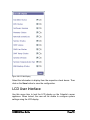
LCD Idle Display .................................................................................... 75
LCD User Interface................................................................................. 76
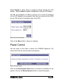
Power Control......................................................................................... 77
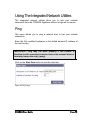
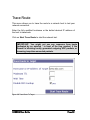
Using The Integrated Network Utilities .................................................. 79
Ping......................................................................................................... 79
Trace Route............................................................................................. 80
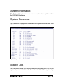
System Information................................................................................... 81
System Processes..................................................................................... 81
System Logs............................................................................................. 81
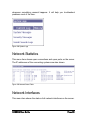
Network Statistics.................................................................................... 82
Network Interfaces .................................................................................. 82
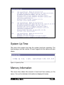
System Up Time....................................................................................... 83
Memory Information ............................................................................... 83
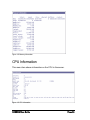
CPU Information .................................................................................... 84
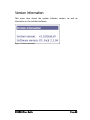
Version Information ................................................................................ 85
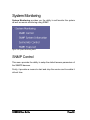
System Monitoring.................................................................................... 86
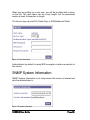
SNMP Control......................................................................................... 86
SNMP System Information ...................................................................... 88
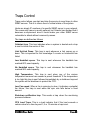
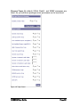
Traps Control.......................................................................................... 89
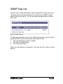
SNMP Trap List ...................................................................................... 91
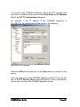
Configuration From Command Line Interface...................................... 92
Local Login Using The Serial Console ................................................... 92
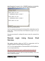
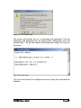
Remote Login Using Secure Shell Services............................................. 95
International Support ............................................................................... 98
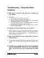
Troubleshooting – Frequently Asked Questions .................................... 99
TABLE OF CONTENT
Appendix A – Resetting Server To Factory Defaults ...........................101
Introduction
Thank you for purchasing a COSMOS (Celestix Open Secure Modular
Operating System) Appliance product. The Celestix Open Secured
Modular Operating System or COSMOS is an appliance OS that runs on
appliances from Celestix. COSMOS has three main features:
•
Open platform
•
Secure by design
•
Modular architecture
COSMOS is an open platform for application developers to run their
application on. It is designed to be modular so that an application can
hook into the web-based user interface, the LCD user interface and the
backup system etc.
Although it is an open platform, security is not compromised.
COSMOS User Guide
Page 1
Configuration Using The Web Browser
COSMOS can be configured and maintained in two ways:
Using a web browser from the network or the Internet.
Using a command line interface, either directly using a serial
console connected from the front panel or using SSH from the
network or Internet.
This section describes the configuration of COSMOS using a web
browser. The command line interface using a serial console or SSH is
discussed in the section Remote Login Using Secure Shell Services on
page 95.
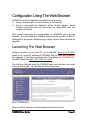
Launching The Web Browser
Using a browser on your client PC, go to the URL https://x.x.x.x:10000
where x.x.x.x is the IP address of COSMOS that you have set up earlier.
For example, if you have configured the IP address as “192.168.6.52”,
the URL should be https://192.168.6.52:10000.
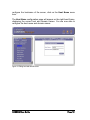
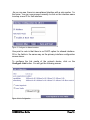
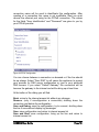
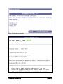
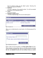
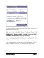
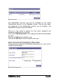
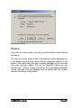
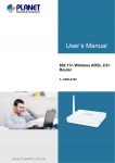
The first time that you enter the COSMOS web user interface, you need
to set up the system. You will see the following screen.
Figure 1 COSMOS setup
There are three options to select during this phase of set up.
COSMOS User Guide
Page 2
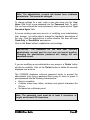
System Preparation. This is used to set up COSMOS for a new
installation or deployment. This will be discussed in detail in the
following section. The following steps are performed.
o Set up web user interface administrator ID and password.
o Set up date, time and time zone.
o Set up the host name.
o Generate SSL certificate for web user interface.
o Select package to install.
o Set up selected package, if any.
Restore System. Use this option to restore your COSMOS
Appliance if you have a previous backup of the system.
Update System. Use this option to install update patches into the
COSMOS Appliance.
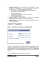
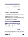
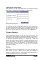
System Preparation
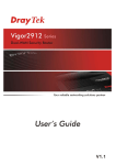
Step 1. Set Up User Name And Password
Figure 2 Setting up admin username and password
The user ID and password of the administrator for the web-browser user
interface is configured here. Enter the user ID of the administrator in the
User Name field. Enter the administrator password in the Password
field and again in the Verify Password field. The two passwords must
match.
Click on the Save button to proceed to the next step.
COSMOS User Guide
Page 3
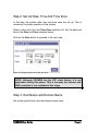
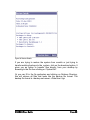
Step 2. Set Up Date, Time And Time Zone
In this step, the system data, time and time zone are set up. This is
necessary for proper operation of the system.
Select a time zone from the Time Zone selection list. Set the date and
time in the Date and Time selection boxes.
Click on the Save button to proceed to the next step.
Figure 3 Configuring time zone, date and time
NOTE. Although COSMOS has the NTP client feature, it is not
applicable during this phase. This is because the Internet and
DNS resolution is not available at this stage.
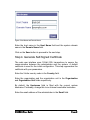
Step 3. Host Name and Domain Name
Set up the system host name and domain name here.
COSMOS User Guide
Page 4
Figure 4 Host Name and Domain Name
Enter the host name in the Host Name field and the system domain
name in the Domain Name field.
Click on the Save button to proceed to the next step.
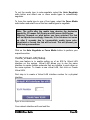
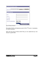
Step 4. Generate Self-Signed Certificate
The web user interface uses 128-bit SSL transactions to secure the
communication between the administrator and the system. A default
certificate is used for the initial configuration. This step regenerates the
certificate with your parameters.
Enter the 2-letter country code in the Country field.
Enter the organization and the organization unit in the Organization
and Organization Unit fields respectively.
By default, the Hostname field is filled with the current system
hostname. Preferably, change this to an Internet resolvable hostname.
Enter the email address of the administrator in the Email field.
COSMOS User Guide
Page 5
Figure 5 Generating SSL Certificate
Click on the Generate Certificate button to proceed to the next step.
When the server has completed the initial system preparation, the web
user interface will restart. Your browser will automatically restart in 5
seconds. If not, click on the link provided in the web page.
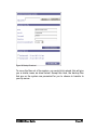
Step 5. Select Package To Install
In this step, the list of packages that can be installed by the wizard is
shown. Select one of the package in the list to install. An example list is
shown below.
Figure 6 Package selection
COSMOS User Guide
Page 6
In the above list, select either one of the package and click on the
Select button to bring up more package related set up items on the left
hand menu. The related set up items are described in the user guide for
the respective package.
Click on the Skip button to skip any package installation.
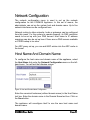
Final Step. Summary
At the final step, a summary of your set up will be displayed before
being implemented. An example is shown below.
Figure 7 Summary of action
In this example, click on the Restart web server button to implement
the set up and restart the web server.
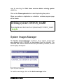
Log In To COSMOS Web User Interface
Using a browser on your client PC, go to the URL https://x.x.x.x:10000
where x.x.x.x is the IP address of the COSMOS Appliance that you have
set up earlier. For example, if you have configured the IP address as
“192.168.6.52”, the URL should be https://192.168.6.52:10000.
Note: Only one user should login and use the Web UI at a time.
COSMOS User Guide
Page 7
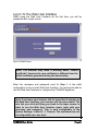
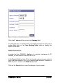
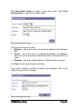
Log In To The Web User Interface
When using the Web User Interface for the first time, you will be
presented with a login screen.
Figure 8 COSMOS log on
Note: The browser may issue a warning about “invalid
certificate” because the new certificate is different from the
initial certificate generated during the wizard setup.
Enter the username and password used for Step 1 of the initial
configuration to log in to the Web User Interface. You will now be able to
use the Web User Interface to configure the COSMOS Appliance.
Note: If you leave your browser idle for more than 5 minutes on
the Web User Interface, your session will become invalid. The
next link you click will bring you back to the login screen. In
order to use the Web User Interface again, login with your
username and password. This is now configurable in the
System Settings -> Web UI -> Timeout. The maximum time out
is configurable up to one hour.
COSMOS User Guide
Page 8
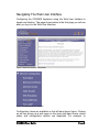
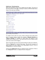
Navigating The Web User Interface
Configuring the COSMOS Appliance using the Web User Interface is
simple and intuitive. The page shown below is the first page you will see
after you log in to the Web User Interface.
Figure 9 Web User Interface main screen
Figure 10 Configuration item selection
Configuration items are available on the left-hand menu frame. Clicking
on an item brings up a web page on the main right-hand frame, where
status and configuration options are displayed. For example, to
COSMOS User Guide
Page 9
configure the hostname of the server, click on the Host Name menu
item.
The Host Name configuration page will appear on the right-hand frame,
displaying the current host and domain names. You are now able to
configure the host name and domain names.
Figure 11 Editing host and domain name
COSMOS User Guide
Page 10
Network Configuration
The network configuration menu is used to set up the network
configuration for the COSMOS Appliance. In this set of menus, the
administrator can set up the system host and domain name. Up to five
network interfaces can be configured here.
Network routing to other networks, hosts or gateways can be configured
from this menu. For the system to operate properly, its DNS resolution
needs to be set up with your DNS servers. Host name to IP address
mappings can also be set up here if there are no DNS servers available
or if DNS lookup is too slow.
For ARP proxy set up, you can add ARP entries into the ARP cache in
the kernel.
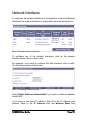
Host Name And Domain Name
To configure the host name and domain name of the appliance, select
the Host Name link under the Network Configuration menu on the lefthand menu. You will get the following screen.
Figure 12 Host and Domain Name Configuration
Enter the canonical hostname (without domain name) in the Host Name
text box. Enter the domain name in the Domain Name text box. Click on
the Save button.
The appliance will reconfigure itself to use the new host name and
domain name.
COSMOS User Guide
Page 11
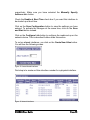
Network Interfaces
To configure the network interfaces of the appliance, select the Network
Interfaces link under the Network Configuration menu as shown below.
Figure 13 Network Interfaces configuration
To configure any of the network interfaces, click on the network
interface name that you wish to edit.
For example, if you want to configure the eth0 interface, click on eth0.
The following screen will be shown.
Figure 14 Configuring a network interface.
Select Obtain Address Automatically if you want to obtain an address
using DHCP.
If you want to use static IP address, then fill in the IP Address and
Network Mask in the IP Address field and Network Mask field
COSMOS User Guide
Page 12
respectively. Make sure you have selected the Manually Specify
Address radio button.
Check the Enable at Boot Time check box if you want this interface to
be started up at boot time.
Click on the Save Configuration button to save the settings you have
entered. To activate the changes at the same time, click on the Save
and Start button instead.
Click on the Configure Link button to configure the media set up on the
network device. This is described further down this section.
To set up aliased interfaces, you click on the Create New Alias button.
You will see the following screen.
Figure 15 Create Aliased Interfaces.
First step is to create an Alias interface number for a physical interface.
Figure 16 Network Interfaces
COSMOS User Guide
Page 13
As you can see, there is a new aliased interface with a sub number 1 in
the name. You can now proceed normally to click on the interface name
to setup a new IP for that interface.
Figure 17 Configure An Aliased Interface
One point to note is that there is no DHCP option for aliased interface.
Fill in the fields in the same way as the primary interface configuration
screen above.
To configure the link media of the network device, click on the
Configure Link button. You will get the following screen.
Figure 18 Link Configuration
COSMOS User Guide
Page 14
To set the media type to auto-negotiate, select the Auto Negotiate
radio button and select one or more media types to automatically
negotiate.
To force the media type to one of four types, select the Force Media
radio button and select one of the four media types to negotiate.
Note. The suffix after the media type denotes the duplexing
capability. FD means Full-Duplex and HD means Half-Duplex.
Warning. Depends on what action you have selected, the link
will be adjusted accordingly. However, if the link does not come
up after 5 seconds due to incompatible media types autonegotiated or forced, the link will be reset. This will prevent you
from losing connections.
Click on the Auto Negotiate or Force Media button to perform your
respective action.
VLAN (Virtual LAN) Setup
One new feature is to enable setting up of an 802.1q Virtual LAN
interface on the system. Virtual LAN allows you to use the same
interface to create multiple networks that are invisible to each other on
the same system. To create a new virtual LAN, first click on Create
Virtual LAN.
First step is to create a Virtual LAN interface number for a physical
interface.
Figure 19 Virtual LAN Interface
Your network interface will now look like.
COSMOS User Guide
Page 15
Figure 20 Network Interfaces
As you can see, there is a new VLAN interface with a sub number 2 in
the name. You can now proceed normally to click on the interface name
to setup a new IP for that interface. One point to note is that the VLAN
interface as well as an alias interfaces can only be working if the primary
interface for it is also active.
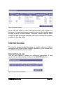
Internet Access
The internet access configuration menu is used to set up an Internet
connection via PPPoE for the COSMOS Appliance. At the moment only
one PPPoE connection can be created.
Internet Access List
This list (see Figure 21) shows the configured connections. A new
connection can be created by clicking on the Add PPPoE button.
Figure 21 Internet Access Information
COSMOS User Guide
Page 16
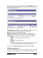
After setting up an Internet connection, the Add PPPoE will not be
shown, instead the screen will display the Internet connection status and
information (see Figure 22):
Figure 22 Internet Connection Information (Online)
Figure 23 Internet Connection Information (Offline)
Connection Name: the name of the connection, useable e.g. for the
dynamic objects in the Check Point Firewall configuration.
Type: present there is only PPPoE possible
Link: shows 'up' if there is an active connection, otherwise 'down'
Gateway: displays 'yes' if you use this connection as default gateway
Action: here you can find links for stopping, starting or debugging
o [stop]
(only if line is up) shutting down the connection
o [start]
(only if line is down) bring line up
o [debug]
(only if line is down) try to bring up the line, shutting down the
line if succeed and display log messages about the test
Clicking on the Connection Name opens the configuration dialog.
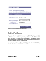
PPPoE Configuration
The PPPoE configuration dialog (see Figure 24) is used to set up the
internet access configuration for the COSMOS Appliance. The
COSMOS User Guide
Page 17
connection name will be used to identificate this configuration. After
creating of a connection this name is not modifiable. Next you must
choose the ethernet port using for the PPPoE connection. The values
for the fields "User Identification" and "Password" are given to you by
your PPPoE provider.
Figure 24 PPPoE Configuration
You can choose between a connection on demand or if the line should
be up always. Select "Peer DNS" to will cause the appliance to prompt
your provider for DNS server configuration or type in your preferred
DNS servers. If you select "Default Gateway" the connection will be
become the gateway to the internet and will be bring up at boot time.
At the botton of the dialog you will find:
Back: return to the internet access list without any changes
Remove: (only if reconfiguration a connection) shutting down the
connection and delete the configuration
Save and Debug: save the configuration, try to connect, shutting down
the line if succeed and display log messages
Save: save configuration and return to internet access list
Save and Start: save configuration, bring up the line and return to
internet access list
COSMOS User Guide
Page 18
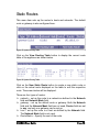
Static Routes
This menu item sets up the routes to hosts and networks. The default
route or gateway is also configured here.
Figure 25 System Routing Table
Click on the View Routing Table button to display the current route
table of the appliance as shown below.
Figure 26 System Routing Table
Click on the New Static Route button to create a new static route or
click on the actual route displayed on the table to edit the respective
route. The screen below will be displayed.
There are four types of routes:
network – set up the route to a network as defined in the Network
field and Network Mask field.
gateway – set up the default route or gateway. Both the Network
field and the Network Mask field are not used, Device field are set
to any, and only one gateway can be set up.
host – set up the route to a host as defined by the Network field.
The Network Mask field is not used.
Route Metric – Specify the cost of the route.
COSMOS User Guide
Page 19
Figure 27 Create New / Modify Existing Route
Fill in the IP address of the route in the Gateway field.
To verify that your route has been successfully entered into the system
routing table, click on the View Routing Table button to display the
system route table.
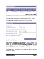
DNS Resolution
In order for the COSMOS Appliance to resolve hostnames to IP
address, its DNS resolver needs to be set up.
In the Search List text box, fill in the domain names you are using in
your local area network. Fill in up to three dotted decimal IP address of
DNS servers to resolve in the DNS Server fields.
Click on the Save button to save the changes in your system.
COSMOS User Guide
Page 20
Figure 28 DNS Resolution.
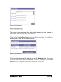
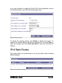
Host Addresses
This menu item configures the static table lookup for host names. It
associates IP Addresses with Host Names.
Click on the Create New Host button to add a new entry. To modify an
existing entry, click on the respective line.
Figure 29 Host Addresses
Fill in the dotted decimal IP address on the IP Address field. Fill in one
or more host names that corresponds to this IP address in the Host
Name text box. Separate each host name with a new line.
COSMOS User Guide
Page 21
Figure 30 Edit Host Entry.
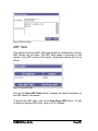
ARP Table
This displays the Proxy ARP Table and allows the configuration of Proxy
ARP entries into the table. The ARP table shows a summary of the
entries in the ARP cache of the kernel. Incomplete entries will not be
shown.
Figure 31 Proxy ARP Table
Click on the View ARP Table button to display the latest information on
the ARP cache in the kernel.
To add a new ARP entry, click on the New Proxy ARP button. To edit
or delete an existing ARP entry, click on its IP address.
COSMOS User Guide
Page 22
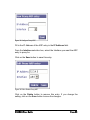
Figure 32 Configure Proxy ARP
Fill in the IP Address of the ARP entry in the IP Address field.
From the Interface selection box, select the Interface you want the ARP
entry to proxy for.
Click on the Save button to save this entry.
Figure 33 Edit or Delete Proxy ARP
Click on the Delete button to remove this entry. If you change the
setting, click on the Save button to save the changes.
COSMOS User Guide
Page 23
Package Manager
The Package manager provides a means to install packages easily and
conveniently. The concept of a package versus a normal package is
simple. A package is a logical group of associated packages predefined
to install in the correct order. This simplifies the install process a great
deal for the administrator since it removes the requirement of knowing
the sequence of packages that is needed to ensure that the package is
correctly installed.
Figure 34 Package Manager
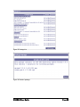
Package List
The picture below shows the Package List, it gives intelligible names to
groups of packages for the user’s convenience. If you click on details
you’ll see a screen with more details about the package and which
packages that will be installed. If you click on the Install option you will
be shown the same information but with Install now option.
COSMOS User Guide
Page 24
Figure 35 Package List
Figure 36 Details of package
COSMOS User Guide
Page 25
Figure 37 Installation of packages
Figure 38 Process of installation
COSMOS User Guide
Page 26
The figure above shows an example of the installation process. Please
wait until the Installation Complete is shown before continuing. If you are
asked to reboot, please do so, since this is critical to complete the
installation process.
Figure 39 After package installation is complete
COSMOS User Guide
Page 27
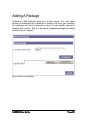
Adding A Package
Clicking on Add Package gives you a new screen. You can either
choose to download from a website or upload a file from your desktop.
The package will first be checked to see if it was digitally signed by
Celestix and is intact. This is to prevent a tempered package from being
installed on your system.
Figure 40 Adding a new package
COSMOS User Guide
Page 28
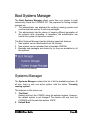
Boot Systems Manager
The Boot Systems Manager allows more than one system to exist
concurrently inside the COSMOS OS. The purposes for having multiple
systems are:
1. The administrator can duplicate the existing (running) system and
use the duplicate system to test new packages.
2. The administrator has the choice of keeping different generation of
the systems after upgrading. If necessary, the administrator can
restore the system to a previous version.
The Boot Systems Manager has the following important features:
1. New system can be downloaded from the Internet.
2. New system can be uploaded from a bootable CDROM.
3. Backups and packages are shared by (ie they are available to) all
the systems.
Figure 41 Boot Systems Manager
Systems Manager
The Systems Manager contains the list of all the available systems. At
all time, there is only one active system, with the status “Currently
running system”.
The features on this screen are:
1. Trial Boot
Restart and boot the COMOS using the selected system. However,
the default system is not changed. This feature will only boot the
COSMOS with the selected system ONCE.
2. Default Boot
COSMOS User Guide
Page 29
Set the selected system as the default system. Selecting this
feature will restart the COSMOS.
3. Duplicate
To make a duplicate of the selected system. You will be prompted
for a name for the duplicated system.
4. Delete
Remove the system.
5. Duplicate current system
To make a duplicate copy of the current default system.
Figure 42 Systems List
When you are duplicating the current system, the following page will be
shown.
Figure 43 Duplicate current system
Enter a name for the new system in the New System Name text box.
When copying a running system, there is a risk that some files are being
used by running processes and cannot be copied correctly. To reduce
that risk, non-essential services can be shutdown during the system
COSMOS User Guide
Page 30
copy by selecting the Shut down services before cloning system
check box.
Click on the Clone system button to start duplicating the system.
When you perform a duplication or a deletion, a status progress page
will be shown.
Figure 44 Progress Update
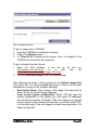
System Images Manager
The System Images Manager contains a list of system images that
was uploaded from CDROMs or downloaded from the Internet. The
CDROMs and Internet download sites are provided by Celestix, as well
as third party developers.
Figure 45 System Images List
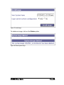
To install a new image, click on the Add new image button.
COSMOS User Guide
Page 31
Figure 46 Install New Image
To get an image from a CDROM:
1. Insert the CDROM into a desktop computer.
2. Clcik on the Browse button.
3. A “Choose File” interface will be shown. Use it to navigate to the
CDROM drive and select the image file.
To get an image from the Internet:
1. Enter the URL address. It can be an ftp site,
or
a
http
site:
ftp.celestix.com/i/123.tar.gz,
www.celestix.com/download/images/123.tar.gz
2. Click on Download image to start the downloading.
eg:
eg.
After obtaining an image, it will be shown on the System Images List
(see Figure 45). You need to Install the image, so that it will be make
available as a system in the Systems Manager.
o New System Name: Give a name to this image. This name will be
shown on the list of the Systems Manager.
o Copy current system configuration: Select YES will copy the
current configuration of the system (eg. Host name, IP addresses
etc) into the new system. Generally, if the new image is an upgrade
or new version of the existing active system, you should select YES.
On the other hand, if the new image is a whole new application, it is
better to select NO.
COSMOS User Guide
Page 32
Figure 47 Install Image
To delete an image, click on the Delete option.
Figure 48 Delete System Image
COSMOS User Guide
Page 33
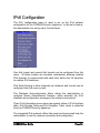
IPv6 Configuration
The IPv6 configuration menu is used to set up the IPv6 network
configuration for the COSMOS Security Appliance. In this set of menus,
the administrator can set up up to five interfaces.
Figure 49 IPv6 menu
One 6to4 tunnel and several 6in4 tunnels can be configured from this
menu. All these tunnels are transition mechanisms allowing isolated
IPv6 domains to communicate with each other before the full transition
to a native IPv6 backbone.
IPv6 Static Routing to other networks via interfaces and tunnels can be
configured from this menu as well.
The Stateless Autoconfiguration Menu allows the administrator to
configure Router Advertisement Daemon, which advertise the IPv6
stateless autoconfiguration message in the network environment.
Three IPv6 information menus show raw system status of IPv6 interface
table, IPv6 Routing Table and IPv6 Neighbor Table, which is collected
from the COSMOS Security Appliance.
The integrated IPv6 network utilities like ping6 and traceroute6 help the
administrator to test the network connection and configuration.
COSMOS User Guide
Page 34
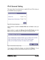
IPv6 General Setting
This menu allows the administrator to enable IPv6 and IPv6 routing on
the COSMOS Security Appliance.
Figure 50 IPv6 General Setting Page
Select whether to enable the Enable IPv6 and click Save to save your
setting.
Select whether to enable the Behave Like An IPv6 Router and click
Save to save your setting. And you will see the following screen:
Figure 51 Please Reboot the System Page
If you want to activate the change, you should click Reboot. Or you
can click Back to skip the rebooting and reboot the system later.
COSMOS User Guide
Page 35
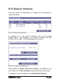
IPv6 Network Interfaces
This menu allows the administrator to configure the IPv6 address of
network interfaces.
Figure 52 IPv6 Network Interfaces Page
To configure any of the network interfaces, click on the network
interface name. For example, if you want to configure the eth0
interface, click on eth0. The following page will be shown.
Figure 53 IPv6 Interface Configuration Page
Select whether to Enable IPv6 at This Interface. Click Save to save
your setting, or click Save and Start to save and activate your setting.
To configure a new IPv6 address, click Add New IPv6 Address.
COSMOS User Guide
Page 36
Figure 54 Add IPv6 Address Page
Fill in the IPv6 address and mask length into IPv6 Address and Mask
Length properly. Click Save to save your setting, or click Save and
Start to save and activate your setting.
If
you
want
to
delete
a
IPv6
address
(eg.
3ffe:1234:5678:9abc:201:69ff:fe00:02f3), click the IPv6 address you
wish to delete. Click Delete to delete the IPv6 address.
Figure 55 Edit IPv6 Address Page
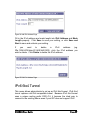
IPv6 6to4 Tunnel
This menu allows administrator to set up an IPv6 6to4 tunnel. IPv6 6to4
tunnel replaces old IPv4-compatible tunnel. Because IPv6 6to4 tunnel
uses a unique routing prefix 2002::/16, it became the ideal way to
connect to the existing 6bone even if your ISP does not support IPv6.
COSMOS User Guide
Page 37
Figure 56 IPv6 to IPv4 Configuration Page (6to4 not running)
For further information on 6to4 tunnel, refer to RFC 3056, Connection of
IPv6 Domains via IPv4 Clouds.
Select whether to Enable 6to4 Tunnel. Select which Local IPv4
Address you wish to use. Fill in a global and routable IPv4 address into
IPv4 Address of 6to4 Relay Router. Click Save to save your setting,
or click Save and Start to save and activate your setting.
If you do not know any of the 6to4 relay router, try the anycast IPv4
address 192.88.99.1, which would search the nearest 6to4 Relay Router
for you.
If the setting is correct, you will see an IPv6 address with 2002::/16
prefix is assigned to the tunnel. The following screen will be shown.
COSMOS User Guide
Page 38
Figure 57 IPv6 to IPv4 Configuration Page (6to4 running)
IPv6 In IPv4 Tunnel
This menu allows the administrator to set up IPv6 in IPv4 tunnels. IPv6
in IPv4 tunnel is a dedicated point-to-point tunnel. So IPv6 in IPv4
tunnel can send IPv6 over an IPv4 backbone. With proper routing
setting, two isolated IPv6 domains will be able to communicate without
the need to upgrade the IPv4 infrastructure.
For further information on IPv6 in IPv4 tunnel, refer to RFC 2893,
Transition Mechanisms for IPv6 Hosts and Routers.
COSMOS User Guide
Page 39
Figure 58 IPv6 in IPv4 Interfaces Page
This menu allows administrator to configure the IPv6 in IPv4 Tunnels.
Click Create New Tunnel to create a new IPv6 in IPv4 tunnel.
Figure 59 New IPv6 in IPv4 Page
Select whether to Enable at This Interface. Fill in a routable IPv4
address into IPv4 Address at Remote Side. Select which Local IPv4
Address you wish to use in the IPv4 Address at Local Side. Fill in a
routable IPv6 address and mask length into IPv6 Address at Local
Side and IPv6 Mask Length at Local Side, respectively.
Click Save to save your setting, or click Save and Start to save and
activate your setting.
COSMOS User Guide
Page 40
If you want to delete or modify the IPv6 in IPv4 tunnel displayed, click on
the Interface Name, you will see the following screen.
Figure 60 Edit IPv6 in IPv4
To delete the existing setting, click Delete to delete this tunnel. To
change the existing setting, change the setting first. And click Save to
save the change, and click Save and Start to save and activate the
change.
IPv6 Static Routes
This menu allows the administrator to set up the static routes including
default gateway.
Figure 61 IPv6 Static Routes Page
COSMOS User Guide
Page 41
Click New Static Route to create a new static route. Click View
Routing Table to see the IPv6 routing table.
Figure 62 New Static Route Page
There are three types of routes:
1. Network – set up the route to a network as defined in the Network
field.
2. Tunnel – set up the route to a network as defined in the Network
field via a tunnel as defined in the Device field. Gateway field is not
used.
3. Gateway – set up the default gateway. Network field is not used.
Click Save to save and activate the setting.
If you want to delete or modify the static route displayed, click on the
actual route you wish to change.
Figure 63 Edit Static Route Page
COSMOS User Guide
Page 42
To delete the existing setting, click Delete to delete this tunnel. To
change the existing setting, change the setting first. And click Save to
save and activate the change.
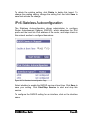
IPv6 Stateless Autoconfiguration
The Stateless Autoconfiguration allows administrator to configure
Router Advertisement Daemon (RADVD), which advertises the IPv6
prefix and the local link IPv6 address of the router, and helps clients in
this network section to configure themselves.
Figure 64 IPv6 Stateless Autoconfiguration Page
Select whether to enable the RADVD service at boot time. Click Save to
save your setting. Click Start/Stop Service to start and stop this
service.
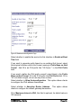
To configure the RADVD setting for an interface, click on the interface
name.
COSMOS User Guide
Page 43
Figure 65 Stateless Autoconfiguration Page
Select whether to enable the service for this interface in Enable at Boot
Time field
If you want to generate prefix based on an existing 6to4 tunnel, select
the physical interface which 6to4 tunnel running in Prefix Base on 6to4
Tunnel. And fill in an IPv6 prefix like “0:0:0:xxxx::” in the IPv6 Prefix
field.
If you want to define the IPv6 prefix yourself, select blank in the Prefix
Base on 6to4 Tunnel, fill in the IPv6 prefix into IPv6 Prefix field. Fill in
“64” into Mask Length, do not use any other number.
Select whether to Allow Autoconfiguration. This option allows clients
to configure the IPv6 address themselves.
Select whether to Advertise Router Address. This option allows
clients to configure the default gateway themselves.
Fill in Maximum Interval of RA, this field is optional, its default value is
300 seconds.
COSMOS User Guide
Page 44
Fill in Minimum Interval of RA, this field is optional, its default value is
100 seconds.
Click Save to save the setting. Click Save and Start to save and
activate the setting.
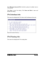
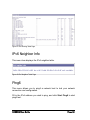
IPv6 Interface Info
This menu item displays the IPv6 status of all interfaces and tunnels.
Figure 66 IPv6 Interface Table Page
IPv6 Routing Info
This menu item displays the IPv6 routing table.
COSMOS User Guide
Page 45
Figure 67 IPv6 Routing Table Page
IPv6 Neighbor Info
This menu item displays the IPv6 neighbor table.
Figure 68 IPv6 Neighbor Table Page
Ping6
This menu allows you to ping6 a network host to test your network
connection and configuration.
Fill in the IPv6 address you wish to ping, and click Start Ping6 to start
ping6 test.
COSMOS User Guide
Page 46
Figure 69 Ping6 Page
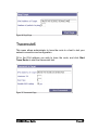
Traceroute6
This menu allows administrator to trace the route to a host to test your
network connection and configuration.
Fill in the IPv6 address you wish to trace the route, and click Start
Trace Route to start the traceroute6 test.
Figure 70 Traceroute6 Page
COSMOS User Guide
Page 47
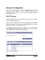
Services Configuration
The services configuration menu allows the administrator to configure
network services available on the COSMOS Appliance. The
administrator is able to start or stop a service, and enable or disable a
service at boot time.
DHCP Server
Enabling the DHCP service allows network clients to get an IP address
from the COSMOS Appliance.
Select whether to enable the DHCP service at boot time, and click Save
to save your setting. You can also click on Start Service to save your
setting, and start the service at the same time.
To configure the DHCP settings for a network, click on the interface
name (eth0, eth1) attached to that network. You will be able to
configure DHCP service settings for that interface.
Figure 71 DHCP server configuration
COSMOS User Guide
Page 48
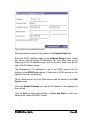
Figure 72 DHCP server configuration for eth0
Enter the domain name for the network in the Domain Name box.
Enter the DHCP address range in the Address Range boxes. These
two values must be dotted IP addresses. The first value must be the
beginning of the IP address range, and the second value must be the
end of the IP address range.
The hostnames or IP addresses of up to two WINS servers can be
entered in the WINS Server boxes. If there are no WINS servers on the
network, they can be left blank.
The IP addresses of up to two DNS servers can be entered in the DNS
Server boxes.
Fill in the Default Gateway box with the IP address of the gateway for
this network.
Click on Save to save your settings, or Save and Start to save your
settings and restart the DHCP server.
COSMOS User Guide
Page 49
List Of Services
This menu allows the administrator to start or stop certain services. It
also allows the administrator to configure services to start at boot time.
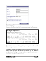
Figure 73 List of services
To change the settings for a particular service, click on the configure
link next to the service.
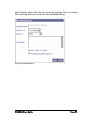
The following configuration box will be shown.
Figure 74 Configuring a service
Select whether to enable this service at boot time. You can save the
setting by click on the Save button, or save your settings and stop the
service by clicking on the Save and Stop Button.
COSMOS User Guide
Page 50
System Settings
The system settings menu allows the administrator to configure system
parameters such as the web user interface and the administrator
account. System back up and restore is also configured from this menu.
For proper operation of the system, the date and time as well as the
time zone can be set up from this menu.
The COSMOS Appliance can be shut down or rebooted from this menu.
For remote access when the network is not accessible from the Internet,
a dial-in console can be set up here.
Figure 75 System Settings
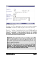
Web User Interface Configuration
The web user interface is used to configure the COSMOS Appliance
using a web browser from the network or Internet. By default, 128-bit
SSL is used and the webui can be accessed at port 10000 at all the
interfaces on the appliance. This menu can be used to configure the IP
address to bind the port to as well as change the port number.
COSMOS User Guide
Page 51
Figure 76 Web UI configuration
To enable the use of 128-bit SSL in the web user interface, check the
Enable SSL check box. To disable any SSL, uncheck the same box.
Check the IP address of the interfaces to bind to in the Bind Interfaces
check boxes. Check the all check box if you want the web user interface
to bind to all interfaces. To make accesses to the web user interface
more secure, bind only to the interfaces that are internal. Then use SSH
or VPN to securely tunnel to these interfaces.
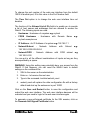
WARNING. If you bind the web user interface to an IP
address of an interface and you change the IP address of
that interface later, the web user interface will not be
accessible anymore. Go to the troubleshooting section on
how to solve this problem.
WARNING. Verify that the new port number is not being
used by any other services by using the Network Stats
menu item in the System Information menu. Services which
bind to a port have LISTEN in their State field.
COSMOS User Guide
Page 52
To change the port number of the web user interface from the default
10000 to another port, fill in this value in the Port Number field.
The Time Out option is to change the web user interface time out
duration.
The function of the Allowed List of IPs field is to enable you to provide
a list of host names and addresses that are allowed to access the
WebUI. The following inputs are valid:
o Hostname - Hostname of a system e.g. myhost
o FQDN Hostname - Hostname with Domain Name e.g.
myhost.example.com
o
o
IP Address - An IP Address of a system e.g. 192.168.1.1
Network/Subnet - Network Address with Subnet
o
192.168.0.0/255.255.240.0
Network/CIDR - Network
Address
with
CIDR
subnet
e.g.
e.g
192.168.0.0/20
You can put in all the different combinations of inputs as long as they
are seperated by a space.
WARNING: Using this setting may potentially deny you access from the
WebUI. If that happens, you can reset the WebUI back to default
settings on the command line.
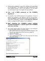
1. SSH to the server as the administrator.
2. Enter su - to become the root user
3.
Type in the command /usr/sbin/webuid_reset
4.
webuid_reset will replace the older configuration file with a factory
default and start up the webserver in port 10000
Click on the Save and Restart button to save the configuration and
restart the web user interface. The web user interface daemon will be
restarted and you need to login to the web user interface again.
To generate a new self-signed certificate for the SSL session, click on
the Generate Self-Signed Certificate button.
COSMOS User Guide
Page 53
Fill in the Country Code, Organization, Organization Unit, Host
Name and Email Address fields. These fields are used to generate a
new certificate for the SSL session.
Click on the Generate Certificate button to generate a new certificate.
WARNING. The current certificate used in this session will be
overwritten with the new certificate. You should reload your
current session in order to use the new certificate.
NOTE. The new certificate will not be activated until you have
restarted your web user interface daemon. You can do this
either in the Services menu or by clicking on the Save and
Restart button in the Web User Interface Configuration.
Figure 77 Generating Self-Signed Certificate
COSMOS User Guide
Page 54
Web User Interface User Account
The web user interface can be administered by more than one user.
Each user shown on the user list is able to log on to the web user
interface, and view or modify settings in the COSMOS system.
The COSMOS system is configured with a default administrator
account, which cannot be deleted. The administrator account user is
also the only user who can log on to the console of the COSMOS
system. Only the username and password of the administrator account
can be changed.
New non-admin users can be created to administer the COSMOS
system.
Each non-admin
permissions.
user
has
either
‘Read-Only’
or
‘Read/Write’
‘Read/Write’ users are able to both view and change settings on the
web user interface.
‘Read-Only’ users are only able to view settings on the web user
interface. They are unable to change settings on the system through the
web user interface.
The access for a non-admin user can also be restricted by reducing the
menu items the user has access to.
These restrictions make it possible to create, for example, ‘Read-Only’
users who only have access to the ‘Network Interface’ portion of the
web user interface, or ‘Read-Write’ users who can change only the
‘System Settings’ portion of the web user interface.
User List
The user list shows all user accounts created and available on the
COSMOS system. Click on a user name to change the user name,
password or ‘read/write’ permissions for that user.
COSMOS User Guide
Page 55
Figure 78 User List
The administrator account user will be indicated by the words
‘Administrator account’ on the ‘Actions’ column. Only the user name
and password for the administrator account can be modified. The
administrator account cannot be deleted.
Click on a user name to change the user name, password and
‘read/write’ permissions for that user.
Click on the ‘Edit permissions’ link to change the menu items available
to a user.
Click on the ‘Delete’ link to delete a user.
Click on the ‘New User’ button to create a new user.
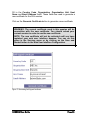
User Account and Creating A New User
The user name, password and read-write permissions for a user can be
modified from this page.
Figure 79 New user account
COSMOS User Guide
Page 56
Note: The administrator account will always have read/write
permissions. This cannot be changed.
To change settings for a user, enter a new user name into the ‘User
Name’ field. Enter a new password into the ‘Password’ field. To verify
that you have entered the correct password, enter it again into the ‘Type
Password Again’ field.
If you are creating a new user account, or modifying a non-administrator
user account, you will be able to change the ‘read/write’ permissions of
the user. Click the radio-buttons to select whether this user will have
‘Read-Only’ or ‘Read/Write’ permissions.
Click on the ‘Save’ button to update the user’s settings.
IMPORTANT. The password for the web user interface
administrator account and the root user are bound together.
Changing the administrator password will change the root
password as well.
If you are modifying a non-administrator user account, a ‘Delete’ button
will also be available. Click on the ‘Delete’ button to delete the currently
displayed user account.
The COSMOS Appliance enforces password sanity to prevent the
administrator from using a password that is easy to crack or guess. A
good password has the following characteristics:
• Easy to remember.
• Contains mixed case letters, numbers and special characters like
$%! etc.
• Not based on a dictionary word.
Note: The password used must be at least 4 characters in
length, and at most 255 characters.
COSMOS User Guide
Page 57
Edit User Permissions
Menu item access for a user can be edited from this page. The layout of
the menu items on this page is exactly the same as the left-hand menu
frame of the web user interface.
Figure 80 Setting user's permissions
To enable a menu item for a user, check on the box next to the menu
item. If a menu category header (for example, ‘Network Interface’ or
‘System Settings’) is checked, all menu items that belong to that
category are checked as well. This means that the user will have access
to all menu items in that category.
Above and below the menu are shortcut buttons to help your selection.
Click on ‘Check all’ to check all the boxes. This will give access to all
menu items to the user, similar to the administrator account. Click on
‘Uncheck all’ to uncheck all boxes.
Click on the ‘Expand all’ button to expand all menu categories. Click on
the ‘Collapse all’ button to collapse all menu categories.
COSMOS User Guide
Page 58
Click on the ‘Save Permissions’ button to save the current settings for
the user. The user may have to login to the web user interface again to
access his or her new settings.
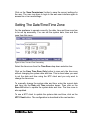
Setting The Date/Time/Time Zone
For the appliance to operate correctly, the date, time and time zone has
to be set up accurately. You can set the system date, time and time
zone from this menu.
Figure 81 Date, Time and Time Zone setting
Select the time zone from the Time Zone drop down selection box.
Click on the Save Time Zone Only button to save only the time zone
without changing the system date and time. This is done when you want
to set the date and time using the NTP client and you only want to
change the time zone.
To manually change the system date and time, enter the current date
and time into the Date and Time selection boxes. Then click on the
Save All button to update the system date and time. The time zone is
also updated.
To use a NTP client to update the system date and time, click on the
NTP Client button. The configuration is described in the next section.
COSMOS User Guide
Page 59
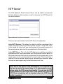
NTP Server
The NTP (Network Time Protocol) Server can be used to synchronise
the time between other servers as well as become the NTP Server for
the whole network.
Figure 82: Network Time Server Configuration
There are two input textbox for the NTP Server Configuration:
List of NTP Servers: This allows the ntpd to mobilize a persistent client
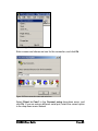
mode association with the specified remote servers or local radio clock.
In this mode the local clock can synchronized to the remote server, but
the remote server can never be synchronized to the local clock.
List of NTP Peers: This is for the NTP daemon to mobilize a persistent
symmetric-active mode association with the specified remote peers. In
this mode the local clock can be synchronized to the remote peer or the
remote peer can be synchronized to the local clock. This is useful in a
network of servers where, depending on various failure scenarios, either
the local or remote peer may be the better source of time.
Note: Due to the nature of the NTP daemon, it is required that
the time be set to the correct time (+/- 5 mins margin or error)
before using the NTP server functionality. You can use the NTP
Client interface to correct the time in the system first. Also the
NTP Client scheduling will be disabled when the NTP Server
facility is enabled.
COSMOS User Guide
Page 60
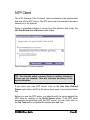
NTP Client
The NTP (Network Time Protocol) client synchronizes the system date
and time with a NTP server. The NTP server can be located in the same
network or in the Internet.
Select a predefined stratum 2 server from the selection box under the
Use Predefined List of Servers radio button.
Figure 83 Network Time Client Configuration
TIP. You should select a server from a country closest to
where you are located. This will increase accuracy of the
synchronization.
If you have your own NTP server, click on the Use User Defined
Server radio button and fill in the server host name in the text box below
that.
Before you use the NTP server, you should verify the server against the
NTP client by clicking on the Verify Server button. If the NTP client
successfully synchronizes with the NTP server, you can then click on
the Set Time button to update the system date and time.
COSMOS User Guide
Page 61
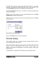
The NTP client can also synchronize with the NTP server on a weekly
schedule. This keeps the system date and time in sync regularly. Click
on the Schedule button to set the schedule as shown below.
Check the Schedule check box to enable the weekly synchronization
with the NTP server.
Select a day of the week to do the synchronization from the Enter
Update Day drop down selection box.
Select the hour of the day to perform the synchronization from the Hour
selection boxes.
Figure 84 Network Time Client Schedule
Click on the Save button to save the schedule.
Remote Syslog
This system allows you to specify external syslog functions and to
receive syslog from other servers.
Note that allowing logs from other system will allow logs from any
system. It does not differentiate where it gets its logs, hence your
firewall rules should be configured to control the syslog. Syslog uses
UDP port 514.
The syslog host, if specified, will send all logs to the remote server.
COSMOS User Guide
Page 62
Figure 85 Remote Syslog
COSMOS Notification System
The COSMOS Notification System configuration menu is used to set up
how the COSMOS Appliance transmit system messages.
COSMOS Notification System Table
This table (see Figure 86) shows which plugin will be activated when the
COSMOS notification system reaches the selected levels. You can
easily change the behavior by selecting a checkbox in the table. Click
on the Save button to save your configuration.
Figure 86 COSMOS Notification System
Note: some notification plugins need to be configured before using. If it
is configurable, so you can find in the last column a link to the
configuration page for the plugin.
COSMOS User Guide
Page 63
CNS PlugIn Configuration
Each plugin has its own configuration dialog. For example the image
(see Figure 87) displays the configuration of the email plugin.
Figure 87 CNS Plugin Configuration
At the top you can see the plugin name inside the title bar. Below there
are rows with plugin specific input fields. In the displayed example you
can see a text box for an email address and another text box for the
relay server. After you have done your inputs click on the Save button.
System Backup
The Backup/Restore system is split into three active parts. The
backup/restore, file transfer and scheduling of backups. This creates an
environment to do immediate backups and restore without having to do
file transfers. Experimental changes to a system are a quick and
painless task because you can easily do a snapshot backup and restore
to a working system. All backups can be transferred directly to your
desktop or your ftp server for safekeeping. You can schedule backups
to be performed at fixed intervals to ensure that the last system
configuration is saved.
Backup
When backup has not been performed yet, the menu will show only
three options: to restore a backup from a remote site, schedule a
backup or to perform a backup. To download a backup, please refer to
the file download sections later in this document
COSMOS User Guide
Page 64
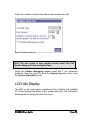
Figure 88 Backup List
When you choose to do a backup, you will be presented with the
following menu. This menu allows you to choose which package (that
has been installed) to be part of the backup and the allows you to put in
comments about this backup.
Figure 89 Backup Now
The Backup Set Name is any name that has no spaces in it and it
defaults to the system host name.
COSMOS User Guide
Page 65
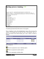
Figure 90 Backup process running
The backup process shows this screen as it progress.
Once a backup is done, the backup/restore menu will now show the
names of the backup with the date and time of the backup. Next to it
there are several icons which allows you to save, restore or delete a
backup.
Figure 91 Backup List
This icon represents a save to desktop option
This icon represents a restore option
This icon represents a delete option.
COSMOS User Guide
Page 66
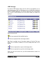
USB Storage
An external USB storage device can be used on the appliance as an
alternative backup. After an USB storage (e.g. an USB stick) is attached
at your COSMOS Appliance, you will see a few new icons in the backup
list. In front of each backup is an icon which shows you where the
backup is:
Figure 92. Backup List USB
This icon represents the harddisk location.
This icon represents the usb-storage location.
Also there is another icon in the action column of the list. This icon
allows you to transfer a backup to the usb storage and back to the
system.
This icon represents a copy to usb-storage option.
This icon represents a copy from usb-storage option.
When you click on the save icon, you will be asked where to save it on
your desktop.
COSMOS User Guide
Page 67
Figure 93 File Download
Restore
If you click on restore option, you will be presented with a menu like the
one below.
The way our restore works is that it will determine which packages are
in the backup and will try to match with the packages installed in the
system. This could mean that some existing packages will be removed
and other packages added. This will be displayed before you can
actually start a restore. During the restore, the unnecessary packages
will be removed, required packages will be added until the system
matches the backup configuration.
COSMOS User Guide
Page 68
Figure 94 Restore Details
If you are trying to restore the system from scratch or just trying to
transfer existing backups to the system, click on the download option. It
gives you an option to transfer files directly from your desktop by
browsing to the file then clicking on “Upload file”.
Or you can fill in the ftp particulars and clicking on Retrieve Directory,
this will retrieve all files that looks like the backup file format. The
backup file format is <backup-set-name>-<Date/time>.tgz
COSMOS User Guide
Page 69
Figure 95 Backup Download
Remember that the active/passive mode of the FTP server is necessary
for correct operation.
After that, the menu will show which files you can upload and you can
choose to get the files.
COSMOS User Guide
Page 70
Figure 96 Backup Download
To move the files out of the system, you would click upload, this will give
you a similar menu as show below. Except this time, the backup files
that are on the system are presented for you to choose to transfer to
your ftp server.
COSMOS User Guide
Page 71
Figure 97 Upload to FTP
Once you click “Save these files”, a new screen shows the ftp process.
Figure 98 Saving to FTP server
Now that you have a working system you may want to do periodic
backups of your system.
Clicking on Schedule will present a menu, this allows you to specify the
backup name and when do you want to backup. You can backup at
specific time of the day, or once a week(on a specific day) or once a
month (also on a specific day and time).
COSMOS User Guide
Page 72
Note however, that it will use the current ftp settings; this is to ensure
that a working ftp server is used for the scheduled backup.
Figure 99 Scheduled Backup
COSMOS User Guide
Page 73
System Update
From time to time, Celestix will release patches for the COSMOS
Appliance. These patches help to keep the system up to date as well as
free from bugs and security exploits. The patches are available as files
that can be downloaded from the Celestix web site.
Figure 100 System Update
Click on the Browse button and select the patch file. Then click on the
Upload File button to upload the file to the system.
The system will verify the gpg signature of the patch against the public
key from Celestix. If it matches, a confirmation screen will be displayed.
Click on the Confirm Update button to proceed with the system update.
Auxiliary Serial Port
When the COSMOS Appliance cannot be remotely accessed from the
local area network or the Internet, a remote dial-in console can be set
up.
Connect a modem to a phone line and connect the serial cable into the
serial port at the rear panel of the COSMOS Appliance.
Select either “Disabled” or “Dial-in” from the Console type selection box
to disable or enable the remote dial-in console respectively.
Select a port speed from the Port Speed selection box.
COSMOS User Guide
Page 74
Select the number of rings before the modem answers the call.
Figure 101 Auxilliary Serial Port
Note: The port speed of your modem should match the Port
Speed setting you have configured here.
Select the Enable debugging output check box if you encounter
problems. View the output log from the System Log menu item under
the System Information menu.
LCD Idle Display
The LCD on the front panel on appliances from Celestix (not available
for FV8xx) displays the status of the system when idle. The information
displayed can be configured from this menu.
COSMOS User Guide
Page 75
Figure 102 LCD Idle Display
Select the information to display from the respective check boxes. Then
click on the Save button to save the configuration.
LCD User Interface
Use this menu item to lock the LCD display on the Celestix’s server
appliance. When locked, the user will be unable to configure system
settings using the LCD display.
COSMOS User Guide
Page 76
Select Normal to allow users to configure settings through the LCD
display. Select Locked to disable configuration using the LCD display.
The PIN (not available on FV8xx) is used to set or reset the password
for the LCD display to be accessed. Note that you should not use 0000
as your PIN as this is the default value for this PIN.
Figure 103 LCD User Interface
Click on the Save button to save your settings.
Power Control
Use this menu to shut down or reboot the COSMOS Appliance. The
screen will show the current system running time.
Figure 104 Power Control
Click on the Shut System Down button to perform a shutdown on the
system. Click on the Reboot System button to reboot the system.
COSMOS User Guide
Page 77
In both cases, a confirmation box will appear asking the administrator to
confirm the action. Click on the OK button to go ahead with the action or
the Cancel button to abort the action.
COSMOS User Guide
Page 78
Using The Integrated Network Utilities
The integrated network utilities allow you to test your network
connection from the COSMOS Appliance without a login on the server.
Ping
This menu allows you to ping a network host to test your network
connection.
Enter the fully qualified hostname or the dotted decimal IP address of
the host to ping.
IMPORTANT: Ping may not work properly if the firewall is
blocking locally generated outgoing icmp-echo-request (ping) or
incoming icmp-echo-reply (pong).
Click on the Start Ping button to start the ping test.
Figure 105 Ping Target
COSMOS User Guide
Page 79
Trace Route
This menu allows you to trace the route to a network host to test your
network connection.
Enter the fully qualified hostname or the dotted decimal IP address of
the host to traceroute.
Click on Start Trace Route to start the network test.
IMPORTANT: You might not see any response from hosts
(indicated by an asterisk * in front of the hop number) if the
firewall is blocking locally generated outgoing UDP packets, or
incoming icmp-time-exceeded packets.
Figure 106 Trace Route To Target
COSMOS User Guide
Page 80
System Information
The System Information menu shows raw system status gathered from
the COSMOS Appliance.
System Processes
This menu item displays the processes running on the server, and their
status.
Figure 107 System Process Time
System Logs
This menu item allows you to check the various system logs.Click on the
system log name to review it. Remember to check the system logs
COSMOS User Guide
Page 81
whenever something unusual happens. It will help you troubleshoot
problems most of the time.
Figure 108 System Logs
Network Statistics
This menu item shows open connections and open ports on the server.
The IP addresses of the connecting systems are also shown.
Figure 109 Network Status Table
Network Interfaces
This menu item shows the status of all network interfaces on the server.
COSMOS User Guide
Page 82
Figure 110 Network Interfaces
System Up Time
This menu item shows how long the system has been operating. The
load average, and the number of users logged into the system are also
shown
Figure 111 System Up Time
Memory Information
This menu item shows the amount of used and free memory on the
server. If no unit is indicated, information is displayed in bytes.
COSMOS User Guide
Page 83
Figure 112 Memory Information
CPU Information
This menu item shows information on the CPU in the server.
Figure 113 CPU Information
COSMOS User Guide
Page 84
Version Information
This menu item shows the system software version, as well as
information on the installed software.
Figure 114 Version Information
COSMOS User Guide
Page 85
System Monitoring
System Monitoring provides you the ability to self-monitor the system
as well as remote monitoring using SNMP.
Figure 115 System Monitoring Menu
SNMP Control
This menu provides the ability to setup the default access parameters of
the SNMPD daemon.
Firstly, it provides a means to start and stop the service and to enable it
at boot time.
COSMOS User Guide
Page 86
Figure 116 Access Control
By default, only the Read Only community is enabled with a public
community string. This is to prevent accidental starting of the service
before the Read/Write access community name is properly saved.
Following that, if you have an SNMP v3 server in your premises, you
can configure access for individual users when you click the “Add new
user” link at the bottom.
COSMOS User Guide
Page 87
When you are setting up a new user, you will be provided with a menu
on the left. The user name can be of any length, but the passwords
require at least 8 characters in length.
The Access type can be R/O (Read Only) or R/W(Read and Write).
Figure 117 New User Menu
Authentication by default is using MD5 encryption to allow connection to
the service.
SNMP System Information
SNMP System Information is to setup where this server is located and
who the administrator is.
Figure 118 System Information
COSMOS User Guide
Page 88
Traps Control
Traps control allows you start and stop the service to send traps to other
SNMP servers. This is to inform them of critical status of the system.
Hosts are simply IP numbers of a specific SNMP server in your network.
The community name is usually optional, but Celestix has decided that it
becomes a requirement since it would make your other SNMP server
vulnerable to attack without community names.
The traps are defined as follows:
Coldstart trap: This trap indicates when a system is booted and a trap
is sent to inform the server of this.
Link Up/Link Down: This trap is sent whenever a link comes up or
down. This is important for the knowledge if a router or hub/switch has
failed.
Low Harddisk space: This trap is sent whenever the harddisk has
reached 80% used capacity.
No Harddisk space: This trap is sent whenever the harddisk has
reached 98% used capacity.
High Temperature: This trap is sent when any of the various
temperature sensors has crossed a preset threshold. If the temperature
is too high this trap is sent followed immediately by a shutdown trap and
the system will be shutdown to protect the CPU.
Low Fan speed: When a fan is spinning to slow, it indicates a potential
fan failure, this trap is sent when the spin rate falls below a fixed
amount.
Shutdown notification trap: This sends a trap when the monitoring
process shutdown.
CPU Load Traps: This is a load indicator that if the load exceeds a
certain value for a time beyond 1,5 or 15 minutes a trap is set.
COSMOS User Guide
Page 89
Process Traps: By default, SSHd, WebUI and SNMP processes are
listed. As you add more packages more processes can be monitored.
Figure 119 Traps Control
COSMOS User Guide
Page 90
SNMP Trap List
Provides a list of trap destinations with the associated community string.
This page shows the trap destination IP, which level of SNMP version
and the community string. You can add new trap destination or delete
them here.
Figure 120 SNMP Trap List
To add trap destination, click on the "Add new trap site" and you will be
presented with a menu that provides three fields to fill in:
1. The trap destination as an IP number.
2. The level of authentication.
3. The community string.
When the trap daemon is restarted, it will use the list of sites to send
traps to.
COSMOS User Guide
Page 91
Configuration From Command Line
Interface
There are two ways to obtain a command-line interface on the
COSMOS Appliance. Both methods make use of software freely
available on the Windows platform or from the Internet. Serial console
login requires the use of a null-modem serial cable.
Note: The COSMOS Appliance will automatically logout any
command-line session that has been idle for more than 5
minutes.
Local Login Using The Serial Console
The administrator can log on to the COSMOS Appliance using the serial
port on the Front Panel, using a null-modem serial cable connected to a
PC or laptop.
This section describes setting up HyperTerminal to connect to the
COSMOS Appliance, allowing the administrator to configure the server
through a serial console.
Attach a null-modem cable from the serial port on the Front Panel of the
COSMOS Appliance to a PC or laptop computer.
Start HyperTerminal on the PC or laptop, and select New Connection
from the File menu.
COSMOS User Guide
Page 92
Figure 121 HyperTerminal Connection
Enter a name and choose an icon for the connection, and click Ok.
Figure 122 Enter connection name and select icon
Select Direct to Com1 in the Connect using drop-down menu, and
click Ok. If you are using a different serial port, select the correct option
in the drop-down menu instead.
COSMOS User Guide
Page 93
Figure 123 Serial Connection Setting
Select 9600 for the Bits per second drop-down menu for the COM
Properties dialog. The other settings can be left alone. Click Ok to
confirm your settings.
Figure 124 Serial Connection Port Setting
COSMOS User Guide
Page 94
HyperTerminal will connect to the COSMOS Appliance automatically.
Press the Enter key a few times so that the login prompt appears.
Figure 125 Login throught serial cable
Use the username and password set during initial configuration (see the
section Step 1. Set Up User Name And Password on page 3.) to log in
to the server.
You can now proceed to configure the server using the command line
interface.
Remote Login
Services
Using
Secure
Shell
This section describes setting up PuTTY to communicate with the
COSMOS Appliance using the Secure Shell protocol.
PuTTY is a free implementation of Telnet and SSH for Win32 platforms.
It can be downloaded from:
http://www.chiark.greenend.org.uk/~sgtatham/putty/download.html.
Once downloaded, the binary can be executed immediately. There is no
need to install the program.
COSMOS User Guide
Page 95
To connect to the COSMOS Appliance, start the PuTTY program and
enter the IP address of the server into the Host Name (or IP address)
field of the PuTTY Configuration dialog box.
For example, if the IP address of the COSMOS Appliance is
192.168.5.50, the configuration will be similar to the following:
Figure 126 PuTTY Configuration
Select the SSH protocol and click on the Open button to connect to the
server.
If you are connecting to the COSMOS Appliance with PuTTY for the first
time, a PuTTY Security Alert window wll appear. Click the Yes button
to store the host key of the COSMOS Appliance locally.
COSMOS User Guide
Page 96
Figure 127 PuTTY Security Alert
The server will prompt you for a username and password. Use the
username and password set up during initial configuration (see the
section Step 1. Set Up User Name And Password on page 3) to log in to
the server.
Figure 128 Console Login
You can now proceed to configure the server using the command-line
interface.
COSMOS User Guide
Page 97
International Support
Your COSMOS Appliance server is backed by a warranty that provides
security and peace of mind. Our worldwide service centers are ready to
lend a helping hand.
If the country you are in does not have a Celestix-authorized service
site, you can contact us by email at [email protected], or by
phone at the following numbers:
America: +1-510-668-0700
Asia: +65-6844-1301
Europe: +49-231-545-2500
You can contact Celestix support for issues related to hardware, or
basic system problems. Should you find any security problems with the
COSMOS Appliance, please contact our security team at
[email protected] .
COSMOS User Guide
Page 98
Troubleshooting – Frequently Asked
Questions
Q. Why can’t I connect to the web user interface on
port 10000?
A: Check that:
The network cable is properly connected.
The IP address or hostname used is correct.
Web UI is bound to the correct IP address. You can check this
in the System Settings -> Web UI screen.
If you are using SSL (which is the default setting), make sure
your URLs start with ‘https://’ instead of ‘http://’.
The firewall policy installed does not block HTTP or HTTPS
traffic to the server itself.
Q: I forgot my root password, how can I reset it?
A: There is no way to reset your root password without resetting to
factory defaults and destroying all data. To reset to factory default,
please refer to the section Appendix A – Resetting Server To
Factory Defaults on page 101.
Q: Why did the SSH host keys change after a “reset to
factory state”?
A: The server will regenerate SSH public and private host keys when it
is reset. This is to ensure that the host keys are unique for each
server.
Q: I get the error message ‘An I/O error occurred during
security authorization. Please try your connection
again’, or an ‘SSL error’ when connecting to the Web
UI.
COSMOS User Guide
Page 99
A: During system preparation, a new SSL certificate will be generated
for the web server. Your browser may reject connections to the
same website because it uses a new certificate. You can restart
your web browser to get it to recognize the new certificate.
Q: Can I set a BIOS password on the COSMOS
Appliance?
A: It is possible to set a BIOS password on the appliance. Connect a
monitor and keyboard to the appliance, and turn on the server.
When the appliance is doing a memory check, press the Del key to
enter BIOS configuration. Choose the Set Supervisor password
option to configure the BIOS password for the appliance.
Q: After changing the COSMOS system settings
throught the browser, I cannot login to the COSMOS
web user interface.
A: This usually happens when the system settings is mis-configured.
To reset the system settings to its default state:
1. Start a SSH session to connect to the COSMOS Appliance (see
Remote Login Using Secure Shell Services on page 95).
2. Login as user admin.
3. Type “su –“ to login as root.
4. Type “/usr/sbin/webuid_reset” to run the script that will restore
the system settings.
Figure 129 Reset WebUI configuration
COSMOS User Guide
Page 100
Appendix A – Resetting Server To Factory
Defaults
The COSMOS Appliance can be reset to a factory default state. Only
someone who has physical access to the server can reset it to the
factory default state.
The following instructions will reset the appliance to the factory default
state.
Reboot the server through the LCD menu, or from the command-line.
The LCD display will show the System On message, and the system
will beep once for system startup.
The LCD display will then show the System Ready message, and the
system will beep again. On this second beep, turn the LCD knob
clockwise a few times.
The system will then boot into rescue mode, and the LCD display will
show the following menu:
Cancel Restore
Reset System
<<<
Turn the LCD knob to move the pointer, and press the LCD knob to
select the option. If the Restore System to Factory Default option is
selected, the hard disk on the server will be formatted, and a new,
factory default image will be installed. If the Reboot System without
restoring option is selected, the system will reboot without performing a
restore operation.
IMPORTANT: The restore operation will destroy all data on the
COSMOS hard disk. If you have any important data stored on
the appliance, do a backup of the data before resetting the
system to factory defaults.
COSMOS User Guide
Page 101