1
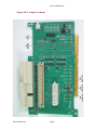
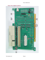
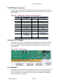
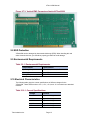
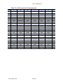
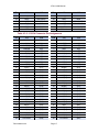
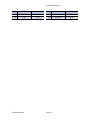
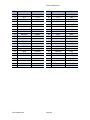
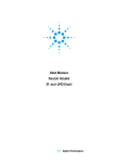
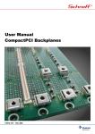
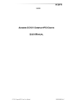
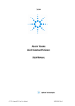
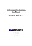
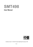
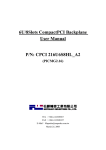
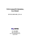
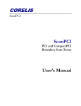
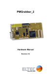
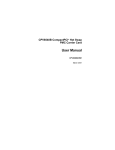
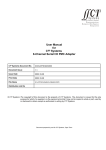
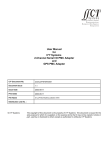
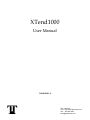
XTend1000
User Manual
TM90020001-A
Twin Industries
Visit: http://www.twinhunter.com
Call: 408-358-2505
[email protected]
Table of Contents
1 Introduction ........................................................................................................4
1.1 Introduction ...............................................................................................4
1.2 Features .....................................................................................................4
1.3 Technical Information ..............................................................................5
2 The Printed Circuit Board .................................................................................6
2.1 Introduction ...............................................................................................6
2.2 Jumper Definitions ...................................................................................6
Table 2.2.1: Jumper Definitions ...............................................................6
Table 2.2.2: Jumper Location ................................................................... 7
2.3 Header Definitions ....................................................................................8
Table 2.3.1: Debug Header Definitions ...................................................8
Table 2.3.2: JTAG Header Definition .......................................................8
Table 2.3.3: CompactPCI IPMB Header Definition .................................8
Figure 2.3.4: Header Locations ............................................................... 9
2.4 VME Connector..........................................................................................10
Table 2.4.1: VME Connector Pin Assignment ........................................10
2.5 ATX Power Connector ..............................................................................11
Table 2.5.1: ATX Power Connector Pin Assignment .............................11
2.6 Local +3.3 V Supply...................................................................................11
Figure 2.6.1: Local +3.3 V Supply.............................................................11
2.7 Installation .................................................................................................12
Figure 2.7.1: XTend1000 Standalone .......................................................12
Figure 2.7.2: XTend1000 PMC Mount ......................................................12
Figure 2.7.3: Vertical PMC Connectors ...................................................13
2.8 ESD Protection .........................................................................................13
2.9 Environmental Requirements ..................................................................13
Table 2.9.1: Environmental Requirements ..............................................13
2.10 Electrical Characteristics .......................................................................13
Table 2.10.1: Current Specifications .......................................................13
3 CompactPCI Interface ........................................................................................14
3.1 Introduction ...............................................................................................14
3.2 Status LEDs ..............................................................................................14
3.3 Pin Assignment ........................................................................................14
Table 3.3.1: P1 Connector Pin Assignments ..........................................14
Table 3.3.2: P2 Connector Pin Assignments ..........................................15
4 PMC Interface .....................................................................................................16
4.1 Introduction ...............................................................................................16
4.2 Status LEDs ..............................................................................................16
4.3 Pin Assignments ......................................................................................16
Table 4.3.1: J11/J12 Connector Pin Assignments ..................................16
Table 4.3.2: J13/J14 Connector Pin Assignments .................................17
5 PCI Interface .......................................................................................................19
5.1 Introduction ...............................................................................................19
5.2 Status LEDs ..............................................................................................19
5.3 Pin Assignments ......................................................................................19
Table 5.3.1: PCI Connector Pin Assignments ........................................19
XTend 1000 Manual
Chapter 1: Introduction
1.1 Introduction
XTend1000 is a 64 bit/66 Mhz PCI extender card designed to provide a flexible, low cost
alternative for CompactPCI or PMC module development. XTend1000 allows an obsolete
or inexpensive PC to take the place of an expensive CompactPCI backplane and/or PMC
carrier card. XTend1000 includes a host of options that allow it to ease development and
lower costs in a wide variety of situations.
The inclusion of an ATX power connector allows XTend1000 to work either standalone
with just a PC compatible power supply, or hosted on an inexpensive PC motherboard. A
built in 3.3V power supply allows XTend1000 to overcome the limitations of older 5V only
backplanes. Access to all PCI signals is provided through a set of debug headers and a
VME connector.
XTend1000 also provides a universal platform for field application engineers. They can
host PMC and cPCI demonstrations or product evaluations with a single XTend1000 card
and power supply. No bulky (and expensive) chassis to lug through airport security or
leave behind at customer sites. Customers benefit, too as they can utilize XTend1000 with
our 48 hour delivery program to begin project/software development instantly.
1.2 Features
The list below is a brief description of XTend1000 features. Refer to the specific section in
the manual for additional information.
Turns a PC Motherboard
Into a CompactPCI or PMC
Module Development System
An effective solution for CompactPCI or PMC development,
with a variety of options, while maintaining a low cost. Utilizing
a typical PC motherboard, the XTend1000 serves as a cPCI
backplane and/or PMC carrier card. It’s an essential tool for
any hardware or software developer.
ATX Power Connector
An ATX Power Connector allows the XTend1000 to be used
without the support of a PC. Providing a unique and cost
effective portable demonstration or evaluation platform.
Built in 10A, 3.3V Power
Supply
Fuse placement selects between an on-board 3.3V supply or
an external source. The built-in supply allows for a 3.3 Volt
environment even in older 5V only backplanes.
Support for 64 bit/66MHz
PCI
The CompactPCI 64EN and PCI M66EN signals are configured by jumpers, empowering operation at a variety of bus
speeds with a 32 or 64-bit bus.
Vertical or Horizontal PMC
Card Mount
Vertical PMC mounting provides easy access to the card for
debugging and signal verification. Horizontal mounting creates a lower-profile connection, perfect for operation within a
PC case.
Debug Header Allows
Access to All PCI Signals
Headers provides access to all PCI signals, allowing the user
to quickly verify signal activity and timing. A JTAG header connected to all three interfaces furnishes additional debug capabilities.
Twin Industries Inc.
Page 4
XTend 1000 Manual
VME Connector
A VME Connector provides quick and convenient access to all
PMC J14 I/O signals.
Local Reset Switch
The local reset switch on the XTend1000 allows for easy
assertion of PCI RST# signal to all interfaces.
Fuses On All Power Inputs
Fuses protect your system and ensure that it cannot be damaged by power-ground shorts, surges, or user error. The
fuses are socketed and there is three available for each
power supply rail.
Status LEDs
Status LEDs allow for simple and effective monitoring of
power, arbitration, and interrupt signals.
1.3 Technical Information
The technical information in this manual is intended to describe the unique features of
XTend1000. It is assumed that the reader has familiarity with the devices and interface
standards incorporated into the XTend1000. This information can be found in the following
manuals and specifications.
PCI
PCI Local Bus Specification,
Revision 2.2
PCI-SIG
CompactPCI
PICMG 2.0 CompactPCI Core
Specification, Revision 3.0
PICMG
PICMG 2.3 PMC on CompactPCI
Specification, Revision 1.0
PICMG
PICMG 2.9 CompactPCI System
Management Specification, Revision 1.0
PICMG
PICMG 2.10 Keying of CompactPCI Boards and BackPlanes
Specification, Revision 1.0
PICMG
IEEE Standard for a Common
Mezzanine Card Family: CMC
IEEE
PMC
Twin Industries Inc.
Page 5
1386-2001
XTend 1000 Manual
Chapter 2: Printed Circuit Board
2.1 Introduction
This chapter describes details associated with the printed circuit board. These include
jumper configurations, header pin-outs, installation, environmental, and electrical characteristics.
2.2 Jumper Definitions
Table 2.2.1: Jumper Definitions
Jumper
Function
J1
Grounds the 64EN signal to CompactPCI P2 on pin B5.
Connecting configures the bus for 64-bit operation.
J2
Grounds the M66EN signal to the PCI connector on pin
B49. Connecting prevents operation of the PCI bus at 34
to 66 MHz.
J30
Connects the PCI clock on PCI pin B16 to the CompactPCI clock.
J31
Connects the PCI clock on PCI pin B16 to the PMC
clock.
J32
Connects the PCI clock on PCI pin B16 to the
XTend1000’s local clock running at 33.333 MHz.
Twin Industries Inc.
Page 6
XTend 1000 Manual
Figure 2.2.2: Jumper Locations
Twin Industries Inc.
Page 7
XTend 1000 Manual
2.3 Header Definition
Table 2.3.1: Debug Header Definitions
Header
Description
H1
Address/Data Lines - AD[31:24]
H2
Address/Data Lines - AD[23:16]
H3
Address/Data Lines - AD[15:8]
H4
Address/Data Lines - AD[7:0]
H5
Bus Command and Byte Enables - CBE[7:0]
H6
Interface Control Signals
H7
Interrupts, Parity, and Control Signals
H8
Arbitration and Error Reporting
H9
Address Lines - AD[63:56]
H10
Address Lines - AD[55:48]
H11
Address Lines - AD[47:40]
H12
Address Lines - AD[39:32]
H13
GND
H14
GND
Table 2.3.2: JTAG Header (H16) Definition
Pin
Description
Pin
Description
1
TDO
2
No Connect
3
TDI
4
TRST
5
No Connect
6
VCC
7
TCK
8
No Connect
9
TMS
10
No Connect
11
No Connect
12
GND
13
No Connect
14
No Connect
15
No Connect
16
GND
Table 2.3.3: CompactPCI IPMB Header (H15) Definition
Pin
Description
Pin
Description
1
SDA
2
SCL
Twin Industries Inc.
Page 8
XTend 1000 Manual
Figure 2.3.4: Header Locations
Twin Industries Inc.
Page 9
XTend 1000 Manual
2.4 VME Connector
A VME Connector provides access to all PMC J14 I/O.
Table 2.4.1: VME Connector Pin Assignment
Pin
Description
Pin
Description
1
J14_1
2
J14_3
3
J14_5
4
J14_7
5
J14_9
6
J14_11
7
J14_13
8
J14_15
9
J14_17
10
J14_19
11
J14_21
12
J14_23
13
J14_25
14
J14_27
15
J14_29
16
J14_31
17
J14_33
18
J14_35
19
J14_37
20
J14_39
21
J14_41
22
J14_43
23
J14_45
24
J14_47
25
J14_49
26
J14_51
27
J14_53
28
J14_55
29
J14_57
30
J14_59
31
J14_61
32
J14_63
33-64
No Connect
33-64
No Connect
65
J14_2
66
J14_4
67
J14_6
68
J14_8
69
J14_10
70
J14_12
71
J14_14
72
J14_16
73
J14_18
74
J14_20
75
J14_22
76
J14_24
77
J14_26
78
J14_28
79
J14_30
80
J14_32
81
J14_34
82
J14_36
83
J14_38
84
J14_40
85
J14_42
86
J14_44
87
J14_46
88
J14_48
89
J14_50
90
J14_52
91
J14_54
92
J14_56
93
J14_58
94
J14_60
95
J14_62
96
J14_64
Twin Industries Inc.
Page 10
XTend 1000 Manual
2.5 ATX Power Connector
In order to remove the limitations of requiring a PC motherboard, an ATX Power Connector is provided to allow the XTend1000 to standalone. A PC compatible power supply is all
that is required.
Table 2.5.1: ATX Power Connector Pin Assignment
Pin
Description
Pin
Description
1
+ 3.3 VDC
11
+ 3.3 VDC
2
+ 3.3 VDC (VI/O)
12
- 12 VDC
3
GND
13
GND
4
+ 5 VDC
14
PS_ON# (GND)
5
GND
15
GND
6
+ 5 VDC
16
GND
7
GND
17
GND
8
PWR_OK
(No Connect)
18
- 5 VDC
(No Connect)
9
+ 5 VSB
(No Connect)
19
+ 5 VDC
10
+ 12 VDC
20
+ 5 VDC
2.6 Local +3.3 V Supply
XTend1000 offers a local + 3.3 V supply that can be enabled by fuse positioning. Placing
fuses in the sockets located near the local supply includes it in the +3.3 V circuit. At no
time should fuses be placed for both supplies. The following figure illustrates the fuse
socket positions.
Figure 2.6.1: +3.3 V Supply
2.7 Installation
XTend1000 can be installed into any PC Motherboard PCI slot or it can standalone, using
the ATX Power Connector. A 33.333 MHz on-board clock can be enabled for operation
when not attached to a PC motherboard. Pull-up resistors on RESET and FRAME# signals ensure interface functionality.
Twin Industries Inc.
Page 11
XTend 1000 Manual
Figure 2.7.1: XTend1000 Standalone
XTend1000 offers two PMC Card mounts, a vertical connection for debugging or a horizontal connection for a lower profile. A VME Connector is also available for access to
PMC J14 I/O.
Figure 2.7.2: XTend1000 PMC Mount
XTend1000 supplies CompactPCI P1 and P2 connectors, allowing for 32 or 64-bit PCI signaling and system slot signals. CompactPCI boards mount vertically, permitting easy
access to the development module.
Twin Industries Inc.
Page 12
XTend 1000 Manual
Figure 2.7.3: Vertical PMC Connectors (back of XTend1000)
2.8 ESD Protection
XTend1000 can be damaged by electrostatic discharge (ESD). When handling this and
other electronic devices, you should be properly grounded to avoid damage.
2.9 Environmental Requirements
Table 2.9.1: Environmental Requirements
Requirement
Specification
Operating Temperature
0 to +55 C, Ambient, At Board
Humidity
0 to 85%
Storage Temperature
-40 to 70 C
2.10 Electrical Characteristics
The following table gives the current specifications of different voltages for the
XTend1000. Status LEDs monitor +3.3 V, +5 V, +12 V, and -12 V connections to attached
modules.
Table 2.10.1: Current Specifications
Twin Industries Inc.
Voltage
Current
+3.3V
Up to 9 A fusing
+5.0V
Up to 9 A fusing
+12.0V
Up to 3 A fusing
-12.0V
Up to 3 A fusing
VI/O
Up to 3 A fusing
Page 13
XTend 1000 Manual
Chapter 3: CompactPCI Interface
3.1 Introduction
XTend1000 offers a CompactPCI backplane connection, conformimg to the PICMG 2.0
specification. A CompactPCI module can be mounted vertically onto XTend1000’s P1 and
P2 connectors. XTend1000 supports CompactPCI modules with up to a 66 MHz PCI clock
and 64-bit address/data bus.
3.2 Status LEDs
Status LEDs monitor activity on REQ#, GNT#, INTA#, INTB#, INTC#, and INTD#.
3.3 Pin Assignments
Table 3.3.1: P1 Connector Pin Assignments
Pin
Z
A
B
C
D
E
F
25
GND
5V
REQ64#
ENUM#
3.3V
5V
GND
24
GND
AD[1]
5V
V(I/O)
AD[0]
ACK64#
GND
23
GND
3.3V
AD[4]
AD[3]
5V
AD[2]
GND
22
GND
AD[7]
GND
3.3V
AD[6]
AD[5]
GND
21
GND
3.3V
AD[9]
AD[8]
M66EN
C/BE[0]#
GND
20
GND
AD[12]
GND
V(I/O)
AD[11]
AD[10]
GND
19
GND
3.3V
AD[15]
AD[14]
GND
AD[13]
GND
18
GND
SERR#
GND
3.3V
PAR
C/BE[1]#
GND
17
GND
3.3V
IPMB_SCL
IPMB_SDA
GND
PERR#
GND
16
GND
DEVSEL#
PCIXCAP
V(I/O)
STOP#
LOCK#
GND
15
GND
3.3V
FRAME#
IRDY#
BD_SEL#
TRDY#
GND
14
13
KEY AREA
12
11
GND
AD[18]
AD[17]
AD[16]
GND
C/BE[2]#
GND
10
GND
AD[21]
GND
3.3V
AD[20]
AD[19]
GND
9
GND
C/BE[3]#
IDSEL
AD[23]
GND
AD[22]
GND
8
GND
AD[26]
GND
V(I/O)
AD[25]
AD[24]
GND
7
GND
AD[30]
AD[29]
AD[28]
GND
AD[27]
GND
6
GND
REQ#
GND
3.3V
CLK
AD[31]
GND
5
GND
BRSVP1A5
BRSVP1B5
PCI_RST#
GND
GNT#
GND
4
GND
IPMB_PWR
HEALTHY#
V(I/O)
INTP
INTS
GND
3
GND
INTA#
INTB#
INTC#
5V
INTD#
GND
2
GND
TCK
5V
TMS
TDO
TDI
GND
1
GND
5V
-12V
TRST#
+12V
5V
GND
Twin Industries Inc.
Page 14
XTend 1000 Manual
Table 3.3.2: P2 Connector Pin Assignments
Pin
Z
A
B
C
D
E
F
22
GND
GA4
GA3
GA2
GA1
GA0
GND
21
GND
RSV
RSV
RSV
RSV
RSV
GND
20
GND
RSV
RSV
RSV
GND
RSV
GND
19
GND
RSV
RSV
RSV
RSV
RSV
GND
18
GND
BRSVP2A18
BRSVP2B18
BRSVP2C18
GND
BRSVP2E18
GND
17
GND
BRSVP2A17
GND
RSV
RSV
RSV
GND
16
GND
BRSVP2A16
BRSVP2B16
RSV
GND
BRSVP2E16
GND
15
GND
BRSVP215
GND
RSV
RSV
RSV
GND
14
GND
AD[35]
AD[34]
AD[33]
GND
AD[32]
GND
13
GND
AD[38]
GND
V(I/0)
AD[37]
AD[36]
GND
12
GND
AD[42]
AD[41]
AD[40]
GND
AD[39]
GND
11
GND
AD[45]
GND
V(I/O)
AD[44]
AD[43]
GND
10
GND
AD[49]
AD[48]
AD[47]
GND
AD[46]
GND
9
GND
AD[52]
GND
V(I/O)
AD[51]
AD[50]
GND
8
GND
AD[56]
AD[55]
AD[54]
GND
AD[53]
GND
7
GND
AD[59]
GND
V(I/O)
AD[58]
AD[57]
GND
6
GND
AD[63]
AD[62]
AD[61]
GND
AD[60]
GND
5
GND
C/BE[5]#
64EN
V(I/O)
C/BE[4]#
PAR64
GND
4
GND
V(I/O)
BRSVP2B4
C/BE[7]#
GND
C/BE[6]#
GND
3
GND
RSV
GND
RSV
RSV
RSV
GND
2
GND
RSV
RSV
UNC
RSV
RSV
GND
1
GND
RSV
GND
RSV
RSV
RSV
GND
Twin Industries Inc.
Page 15
XTend 1000 Manual
Chapter 4: PMC Interface
4.1 Introduction
XTend1000 offers two PMC card mounts, vertical and horizontal. Attached modules can
operate with a 32 or 64-bit address/data bus at 33Mhz or 66Mhz PCI. PMC P14 I/O is
routed to a VME connector for quick and convenient access.
4.2 Status LEDs
Status LEDs monitor activity on REQ#, GNT#, INTA#, INTB#, INTC#, and INTD#.
4.3 Pin Assignments
Table 4.3.1: J11/J12 Connector Pin Assignments
Pin
J11
J12
Pin
J11
J12
1
TCK
+12V
2
-12V
TRST#
3
GND
TMS
4
INTA#
TDO
5
INTB#
TDI
6
INTC#
GND
7
BUSMODE1#
GND
8
+5V
PCI-RSVD
9
INTD#
PCI-RSVD
10
PCI-RSVD
PCI-RSVD
11
GND
BUSMODE2#
12
PCI-RSVD
+3.3V
13
CLK
RST#
14
GND
BUSMODE3#
15
GND
+3.3V
16
GNT#
BUSMODE4#
17
REQ#
PCI-RSVD
18
+5V
GND
19
V(I/O)
AD[30]
20
AD[31]
AD[29]
21
AD[28]
GND
22
AD[27]
AD[26]
23
AD[25]
AD[24]
24
GND
+3.3V
25
GND
IDSEL
26
C/BE[3]#
AD[23]
27
AD[22]
+3.3V
28
AD[21]
AD[20]
29
AD[19]
AD[18]
30
+5V
GND
31
V(I/O)
AD[16]
32
AD[17]
C/BE[2]#
33
FRAME#
GND
34
GND
PMC-RSVD
35
GND
TRDY#
36
IRDY#
+3.3V
37
DEVSEL#
GND
38
+5V
STOP#
39
GND
PERR#
40
LOCK#
GND
41
SDONE#
+3.3V
42
SBO#
SERR#
43
PAR
C/BE[1]#
44
GND
GND
45
V(I/O)
AD[14]
46
AD[15]
AD[13]
47
AD[12]
GND
48
AD[11]
AD[10]
49
AD[9]
AD[8]
50
+5V
+3.3V
51
GND
AD[7]
52
C/BE[0]#
PMC-RSVD
Twin Industries Inc.
Page 16
XTend 1000 Manual
Pin
J11
J12
Pin
J11
J12
53
AD[6]
+3.3V
54
AD[5]
PMC-RSVD
55
AD[4]
PMC-RSVD
56
GND
GND
57
V(I/O)
PMC-RSVD
58
AD[3]
PMC-RSVD
59
AD[2]
GND
60
AD[1]
PMC-RSVD
61
AD[0]
ACK64#
62
+5V
+3.3V
63
GND
GND
64
REQ64#
PMC-RSVD
Table 4.3.2: J13/J14 Connector Pin Assignments
Pin
J13
J14
Pin
J13
J14
1
PCI-RSVD
C[1]
2
GND
A[1]
3
GND
C[2]
4
C/BE[7]#
A[2]
5
C/BE[6]#
C[3]
6
C/BE[5]#
A[3]
7
C/BE[4]#
C[4]
8
GND
A[4]
9
V(I/O)
C[5]
10
PAR64
A[5]
11
AD[63]
C[6]
12
AD[62]
A[6]
13
AD[61]
C[7]
14
GND
A[7]
15
GND
C[8]
16
AD[60]
A[8]
17
AD[59]
C[9]
18
AD[58]
A[9]
19
AD[57]
C[10]
20
GND
A[10]
21
V(I/O)
C[11]
22
AD[56]
A[11]
23
AD[55]
C[12]
24
AD[54]
A[12]
25
AD[53]
C[13]
26
GND
A[13]
27
GND
C[14]
28
AD[52]
A[14]
29
AD[51]
C[15]
30
AD[50]
A[15]
31
AD[49]
C[16]
32
GND
A[16]
33
GND
C[17]
34
AD[48]
A[17]
35
AD[47]
C[18]
36
AD[46]
A[18]
37
AD[45]
C[19]
38
GND
A[19]
39
V(I/O)
C[20]
40
AD[44]
A[20]
41
AD[43]
C[21]
42
AD[42]
A[21]
43
AD[41]
C[22]
44
GND
A[22]
45
GND
C[23]
46
AD[40]
A[23]
47
AD[39]
C[24]
48
AD[38]
A[24]
49
AD[37]
C[25]
50
GND
A[25]
51
GND
C[26]
52
AD[36]
A[26]
53
AD[35]
C[27]
54
AD[34]
A[27]
55
AD[33]
C[28]
56
GND
A[28]
57
V(I/O)
C[29]
58
AD[32]
A[29]
59
PCI-RSVD
C[30]
60
PCI-RSVD
A[30]
Twin Industries Inc.
Page 17
XTend 1000 Manual
Pin
J13
J14
Pin
J13
J14
61
PCI-RSVD
C[31]
62
GND
A[31]
63
GND
C[32]
64
PCI-RSVD
A[32]
Twin Industries Inc.
Page 18
XTend 1000 Manual
Chapter 5: PCI Interface
5.1 Introduction
XTend1000 mounts on a common PCI bus connector. It is capable of operating on a system with up to a 66 MHz PCI clock and 64-bit address/data bus. Fuse placement can
enable XTend1000’s on-board 3.3 V power supply for PCI backplanes that only offer a 5
Volt signal.
5.2 Status LEDs
Status LEDs monitor activity on REQ#, GNT#, INTA#, INTB#, INTC#, and INTD#.
5.3 Pin Assignments
Table 5.3.1: PCI Connector Pin Assignments
Pin
B
A
Pin
B
A
1
-12V
TRST#
2
TCK
+12V
3
GROUND
TMS
4
TDO
TDI
5
+5V
+5V
6
+5V
INTA#
7
INTB#
INTC#
8
INTD#
+5V
9
PRSNT1#
Reserved
10
Reserved
+ VI/O
11
PRSNT2#
Reserved
12
KEYWAY
KEYWAY
13
KEYWAY
KEYWAY
14
Reserved
3.3 Vaux
15
GROUND
RST#
16
CLK
+ VI/O
17
GROUND
GNT#
18
REQ
GROUND
19
+ VI/O
PME#
20
AD31
AD30
21
AD29
+ 3.3 V
22
GROUND
AD28
23
AD27
AD26
24
AD25
GROUND
25
+ 3.3 V
AD24
26
C/BE3#
IDSEL
27
AD23
+ 3.3 V
28
GROUND
A22
29
AD21
AD20
30
AD19
GROUND
31
+ 3.3 V
AD18
32
AD17
AD16
33
C/BE2#
+ 3.3 V
34
GROUND
FRAME#
35
IRDY#
GROUND
36
+ 3.3 V
TRDY#
37
DEVSEL#
GROUND
38
GROUND
STOP#
39
LOCK#
+ 3.3 V
40
PERR#
Reserved
41
+ 3.3 V
Reserved
42
SERR#
GROUND
43
+3.3 V
PAR
44
C/BE1#
AD15
45
AD14
+ 3.3 V
46
GROUND
AD13
47
AD12
AD11
48
AD10
GROUND
49
M66EN
AD9
50
KEYWAY
KEYWAY
Twin Industries Inc.
Page 19
XTend 1000 Manual
Pin
B
A
Pin
B
A
51
KEYWAY
KEYWAY
52
AD8
C/BE0#
53
AD7
+3.3V
54
+ 3.3 V
AD6
55
AD5
AD4
56
AD3
GROUND
57
GROUND
AD2
58
AD1
AD0
59
+ VI/O
+ VI/O
60
ACK64#
REQ64#
61
+5V
+5V
62
+5V
+5V
63
Reserved
GROUND
64
GROUND
C/BE7#
65
C/BE6#
C/BE5#
66
C/BE4#
+ VI/O
67
GROUND
PAR64
68
AD63
AD62
69
AD61
GROUND
70
+ VI/O
AD60
71
AD59
AD58
72
AD57
GROUND
73
GROUND
AD56
74
AD55
AD54
75
AD53
+ VI/O
76
GROUND
AD52
77
AD51
AD50
78
AD49
GROUND
79
+ VI/O
AD48
80
AD47
AD46
81
AD45
GROUND
82
GROUND
AD44
83
AD43
AD42
84
AD41
+ VI/O
85
GROUND
AD40
86
AD39
AD38
87
AD37
GROUND
88
+ VI/O
AD36
89
AD35
AD34
90
AD33
GROUND
91
GROUND
AD32
92
Reserved
Reserved
93
Reserved
GROUND
94
GROUND
Reserved
Twin Industries Inc.
Page 20