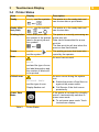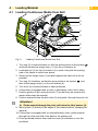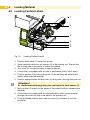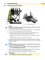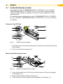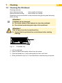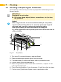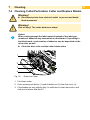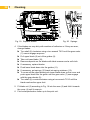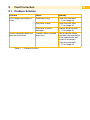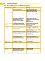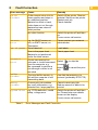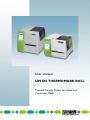
1
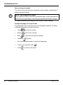
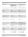
User manual UM EN THERMOMARK ROLL Thermal Transfer Printer for Labels and Continuous Media User manual Thermal Transfer Printer for Labels and Continuous Media 2012-04-13 Designation: UM EN THERMOMARK ROLL Version: 03 Order No.: – This user manual is valid for: Designation THERMOMARK ROLL THERMOMARK ROLL AR THERMOMARK ROLL X1 104611_en_03 Order no. 5146477 5146749 5146723 PHOENIX CONTACT i 3 General terms and conditions of use for technical documentation Phoenix Contact reserves the right to alter, correct, and/or improve the technical documentation and the products described in the technical documentation at its own discretion and without giving prior notice, insofar as this is reasonable for the user. The same applies to any technical changes that serve the purpose of technical progress. The receipt of technical documentation (in particular user documentation) does not constitute any further duty on the part of Phoenix Contact to furnish information on modifications to products and/or technical documentation. You are responsible to verify the suitability and intended use of the products in your specific application, in particular with regard to observing the applicable standards and regulations. All information made available in the technical data is supplied without any accompanying guarantee, whether expressly mentioned, implied or tacitly assumed. In general, the provisions of the current standard Terms and Conditions of Phoenix Contact apply exclusively, in particular as concerns any warranty liability. This manual, including all illustrations contained herein, is copyright protected. Any changes to the contents or the publication of extracts of this document is prohibited. Phoenix Contact reserves the right to register its own intellectual property rights for the product identifications of Phoenix Contact products that are used here. Registration of such intellectual property rights by third parties is prohibited. Other product identifications may be afforded legal protection, even where they may not be indicated as such. Internet How to contact us Up-to-date information on Phoenix Contact products and our Terms and Conditions can be found on the Internet at: www.phoenixcontact.com Make sure you always use the latest documentation. It can be downloaded at: www.phoenixcontact.net/catalog Subsidiaries If there are any problems that cannot be solved using the documentation, please contact your Phoenix Contact subsidiary. Subsidiary contact information is available at www.phoenixcontact.com. Published by PHOENIX CONTACT GmbH & Co. KG Flachsmarktstraße 8 32825 Blomberg GERMANY Should you have any suggestions or recommendations for improvement of the contents and layout of our manuals, please send your comments to: [email protected] 104611_en_03 PHOENIX CONTACT ii THERMOMARK ROLL 4 Note on the print media The result of the print depends essentially on the suitable combination of material and print ribbon. NOTE: Use suitable print media A low-quality ink ribbon can lead to premature wear on the printhead and result in a poor print image. Use only print media from Phoenix Contact. You can find suitable print media in the Phoenix Contact catalog. Change language of Touch Screen The language of the Touch Screen is set to English by default. To select a different language, proceed as follows: iii • Touch to open the menu. • Select then for the settings. • With • Touch the • Use the horizontal arrows to select your language. • Confirm your selection with • Touch PHOENIX CONTACT , you access the regional settings. symbol. . to return to the menu. 104611_en_03 5 Technical data THERMOMARK ROLL THERMOMARK ROLL AR THERMOMARK ROLL X1 Thermal transfer, thermal direct Thermal transfer, thermal direct Position Center Center Detection Label gap, black mark and punchhole mark Label gap, black mark and punchhole mark Resolution Print mode CPU Material sensor Type Print speed Print length 300 dpi x 300 dpi (12 points/mm x 12 points/mm) 32 Bit/400 MHz Gap sensor 30 mm/s ... 125 mm/s 300 dpi x 300 dpi (12 points/mm x 12 points/mm) 32 Bit/400 MHz Gap sensor 30 mm/s ... 125 mm/s At least 5 mm, maximum 1000 mm At least 5 mm, maximum 1000 mm Maximum 152 mm Maximum 205 mm Internal core diameter 38.1 mm … 76 mm 38.1 mm ... 76 mm Length Maximum 300 m Maximum 300 m Internal core diameter 25.4 mm 25.4 mm USB 2.0, Full speed slave, Ethernet 10/100Base-T USB 2.0, Full speed slave, Ethernet 10/100Base-T Print width Print medium Outside diameter of the roll of labels Ink ribbon Outside diameter of the ink ribbon reel Ink side Interfaces Maximum 104 mm Maximum 68 mm Outside 1 x USB master, 500 mA (back side) Display and Operation Voltage Power Temperature Maximum 104 mm Maximum 68 mm Outside 1 x USB master, 500 mA (back side) 2 x USB master, 100 mA (front side) Touch display with 160 x 255 pixels, 96.31 mm diagonal Touch display with 160 x 255 pixels, 96.31 mm diagonal Maximal 100 W Maximal 100 W 100 V AC ... 240 V AC, 50/60 Hz, PFC 100 V AC ... 240 V AC, 50/60 Hz, PFC Operation +5 °C ... +35 °C +5 °C ... +35 °C Transport -25 °C ... +60 °C -25 °C ... +60 °C Bearings Humidity 0 °C ... +60 °C 0 °C ... +60 °C Operation 10 % ... 85 %, not condensing 10 % ... 85 %, not condensing Transport 20 % ... 80 %, not condensing 20 % ... 80 %, not condensing Bearings 104611_en_03 20 % ... 80 %, not condensing 20 % ... 80 %, not condensing PHOENIX CONTACT iv THERMOMARK ROLL 6 Technical data Approvals THERMOMARK ROLL X1 5146477: CE, FCC class A, UL, CB 5146723: CE, FCC class A, UL, CB 189 mm x 320 mm x 253 mm 245 mm x 412 mm x 264 mm Cutter THERMOMARK ROLL-CUTTER THERMOMARK ROLL X1-CUTTER Media hub THERMOMARK ROLL-ERH – Dimensions (H x D x W) Weight Optional extensions Perforation cutter v THERMOMARK ROLL THERMOMARK ROLL AR PHOENIX CONTACT 5146749: CE, FCC class A, UL, CB, S-Mark 3.5 kg THERMOMARK ROLL-CUTTER/P 5.0 kg THERMOMARK ROLL X1-CUTTER/P 104611_en_03 Table of Contents 1 1.1 1.2 1.3 1.4 1.5 2 2.1 2.2 2.3 2.3.1 2.3.2 2.3.3 2.4 3 3.1 3.2 3.3 3.4 3.5 3.6 4 4.1 4.2 4.3 5 5.1 5.2 6 6.1 6.2 7 7.1 7.2 7.3 7.4 8 8.1 8.2 9 Introduction.................................................................................................. 8 Product Description......................................................................................................... 8 Instructions...................................................................................................................... 8 Intended Use................................................................................................................... 9 Safety Instructions........................................................................................................... 9 Environment.................................................................................................................. 10 Installation.................................................................................................. 11 Device Overview........................................................................................................... 11 Unpacking and Setting-up the Printer........................................................................... 14 Connecting the Device.................................................................................................. 15 Connecting to the Power Supply............................................................................... 15 Connecting to a Computer via USB.......................................................................... 16 Connecting to a Network via Ethernet...................................................................... 16 Switching on the Device................................................................................................ 17 Touchscreen Display................................................................................. 18 Structure of the Touchscreen Display............................................................................ 18 Operating the Touchscreen Display.............................................................................. 18 Symbols on the Start Display........................................................................................ 18 Printer States................................................................................................................. 19 Configure Ethernet Interface......................................................................................... 20 Perform Test Print.......................................................................................................... 20 Loading Material........................................................................................ 21 Loading Continuous Media from Roll............................................................................ 21 Loading Fanfold Labels................................................................................................. 22 Loading Transfer Ribbon............................................................................................... 23 Option......................................................................................................... 25 Cutter/Perforation Cutter............................................................................................... 25 External Supply Hub .................................................................................................... 26 Printing Operation..................................................................................... 27 Printing in Tear-off Mode............................................................................................... 27 Printing in Cutting Mode................................................................................................ 27 Cleaning...................................................................................................... 28 Cleaning Instructions..................................................................................................... 28 Cleaning the Printhead.................................................................................................. 29 Cleaning or Replacing the Print Roller.......................................................................... 30 Cleaning Cutter/Perforation Cutter and Replace Blades............................................... 31 Fault Correction......................................................................................... 33 Problem Solution........................................................................................................... 33 Error Messages and Fault Correction........................................................................... 34 Licences...................................................................................................... 36 9.1 9.2 9.3 EC Declaration of Conformity........................................................................................ 36 FCC............................................................................................................................... 38 GPL Code Statement.................................................................................................... 38 10 Index............................................................................................................ 39 7 8 1 Introduction 1.1 Product Description The device is an industrial thermal transfer printer for printing labels and continuous media. 1.2 Instructions Important information and instructions in this documentation are designated as follows: Danger! Draws your attention to an exceptionally grave, impending danger to your health or life. ! ! i Indicates a hazardous situation that could lead to injuries or material damage. Attention! Draws attention to possible dangers, material damage or loss of quality. Notice! Gives you tips. They make a working sequence easier or draw attention to important working processes. Environment! Warning! Gives you tips on protecting the environment. Handling instruction Reference to section, position, illustration number or document. Option (accessories, peripheral equipment, special fittings). Zeit Information in the display. 1 Introduction 1.3 Intended Use • The device is manufactured in accordance with the current technological status and the recognized safety rules. However, danger to the life and limb of the user or third parties and/or damage to the device and other tangible assets can arise during use. • The device may only be used for its intended purpose and if it is in perfect working order, and it must be used with regard to safety and dangers as stated in the operating manual. • The device printer is intended exclusively for printing suitable materials. Any other use or use going beyond this shall be regarded as improper use. The manufacturer/supplier shall not be liable for damage resulting from unauthorized use; the user shall bear the risk alone. • Usage for the intended purpose also includes complying with the operating manual, including the manufacturer‘s maintenance recommendations and specifications. i Notice! The complete documentation is included in the scope of delivery on DVD, and can also currently be found in the Internet. 1.4 Safety Instructions • The device is configured for voltages of 100 to 240 V AC. It only has to be plugged into a grounded socket. • Only connect the device to other devices which have a protective low voltage. • The device may only be used in a dry environment, do not expose it to moisture (sprays of water, mists, etc.). • Do not use the device in an explosive atmosphere. • Do not use the device close to high-voltage power lines. • If the device is operated with the cover open, ensure that people‘s clothing, hair, jewelry etc. do not come into contact with the exposed rotating parts. • The device or parts of it can become hot while printing. Do not touch during operation, and allow to cool down before changing material and before disassembly. • Risk of crushing when closing the cover. Touch the cover at the outside only. Do not reach into the swivel range of the cover. • Perform only those actions described in this operating manual. Work going beyond this may only be performed by trained personnel or service technicians. • Unauthorized interference with electronic modules or their software can cause malfunctions. 9 10 1 Introduction • Other unauthorized work on or modifications to the device can also endanger operational safety. • Always have service work done in a qualified workshop, where the personnel have the technical knowledge and tools required to do the necessary work. • There are various warning stickers on the device. They draw your attention to dangers. Warning stickers must therefore not be removed, as then you and other people cannot be aware of dangers and may be injured. • The maximum sound pressure level is less than 70 dB(A). Danger! Danger to life and limb from power supply. XX Do not open the device casing. 1.5 Environment Obsolete devices contain valuable recyclable materials that should be sent for recycling. XX Send to suitable collection points, separately from residual waste. The modular construction of the printer enables it to be easily disassembled into its component parts. XX Send the parts for recycling. The electronic circuit board of the device is equipped with a lithium battery. XX Take old batteries to collection boxes in shops or public waste disposal centers.. 2 11 Installation 2.1 Device Overview 1 2 8 3 1 2 3 4 5 6 7 8 Cover Margin stops Roll retainer Ribbon supply hub Ribbon take-up hub Belt roller Print mechanics Touchscreen display 4 5 6 7 Fig. 1 THERMOMARK ROLL with Tear-off Plate 9 Cutter or Perforation Cutter 9 Fig. 2 THERMOMARK ROLL with Cutter or Perforation Cutter 12 2 Installation 1 2 8 3 4 1 2 3 4 5 6 7 8 9 Cover Margin stops Roll retainer Ribbon supply hub Ribbon take-up hub Belt roller Print mechanics Touchscreen display 2 USB master ports (Imax= 100 mA) 5 9 6 7 Fig. 3 THERMOMARK ROLL X1 with Tear-off Plate 10 Cutter or Perforation Cutter 10 Fig. 4 THERMOMARK ROLL X1 with Cutter or Perforation Cutter 2 13 Installation 11 12 13 14 15 17 Fig. 5 16 Print Mechanics 11 Label sensor 12 Printhead retainer with printhead 13 Print roller 14 Guides 15 Knob for adjusting the guides 16 Lever for locking the printhead 17 Tear-off plate 14 2 Installation 2.2 Unpacking and Setting-up the Printer XX Lift the label printer out of the box and set it up on a level surface. XX Check label printer for damage which may have occurred during transport. XX Check delivery for completeness. Contents of Delivery: • Label Printer • Power Cable Type E+F • USB Cable • Operator's Manual • DVD with application software CLIP PROJECT, driver and documentation • Transfer ribbon • Continuous labels on roll i Notice! Please keep the original packaging in case the printer must be returned. i Notice! When transporting the printer remove the transfer ribbon and media. ! Attention! The device and printing materials will be damaged by moisture and wetness. XX Set up label printers only in dry locations protected from splash water. 2 Installation 15 2.3 Connecting the Device 1 2 3 4 1 Power switch 2 USB master ports for keyboard, scanner, or memory stick 3 USB full-speed slave port 4 Ethernet 10/100 Base-T 5 Power connection jack 5 Fig. 6 Connections 2.3.1 Connecting to the Power Supply The printer is equipped with a wide area power unit for a supply voltage of 100 V to 240 V. 1. Check that the device is switched off. 2. Plug the power cable into the power connection jack (5). 3. Plug the power cable into a grounded socket. 16 2 Installation 2.3.2 Connecting to a Computer via USB ! Attention! Inadequate or no grounding can cause malfunctions during operations. XX Ensure that all computers and cables connected to the label printer are grounded. In order to connect the printer to a USB interface a printer driver must be installed. The adequate driver for your device can be found on the DVD included in the contents of delivery or on the internet at www.phoenixcontact.net/catalog. XX Switch on computer. XX Terminate all running tasks. XX Switch on THERMOMARK ROLL. XX Connect computer with THERMOMARK ROLL using the included USB cable. XX Insert DVD with the driver software into the DVD drive. XX The Windows installation wizard is started automatically. XX Follow the instructions on the screen. XX When the error message "Windows logo test failed" appears, still continue the installation. After a successful installation an icon for the THERMOMARK ROLL appears in the windows system directory "Printer". CLIP PROJECT Afterwards, configure the THERMOMARK ROLL in the planning and marking software CLIP PROJECT in the module "Marking". XX Add the THERMOMARK ROLL as a new printer in CLIP PROJECT "Marking" under „File... configure output device...“. 2.3.3 Connecting to a Network via Ethernet The integrated Ethernet interface allows the operation of the printer in a network. To connect the printer to a network outlet a patch cable with a RJ45 plug for 10Base or 100Base-T is necessary. ! Attention! When connecting the printer to the network a shielded cable must necessarily be used. XX Connect computer to a printer by a suitable cable. 2 Installation 17 2.4 Switching on the Device When all connections have been made: XX Switch the printer on at the power switch (1). The printer performs a system test, and then shows the system status READY in the touchscreen display. 1 If an error occurs during the system test, the symbol , Critical fault and type of error are displayed. Fig. 7 Power Switch 18 3 Touchscreen Display 3.1 Structure of the Touchscreen Display The touchscreen display (1) indicates the current status of the printer and the print job, indicates faults and shows the printer settings in the menu. 1 READY By selecting the buttons on the touchscreen display (1) settings can be made. Fig. 8 Touchscreen Display 3.2 Operating the Touchscreen Display The touchscreen display is operated directly by touch: • To open a menu or select a menu item lightly touch the corresponding symbol. • To scroll in lists slide finger up or down on the display. 3.3 Symbols on the Start Display Symbol Status Function Ready To offline menu Error Ready Feeds a blank label Ready After the end of a print job, reprint the last label Printing label Interrupt print job, printer goes into "Pause" state Pause Continue the print job, printer goes into "Printing label" state Error Ready Delete internal memory, the last label can no longer be reprinted. Printing label Cancel current print job and delete all print jobs. Pause Error Table 1 Symbols on the Start Display 3 Touchscreen Display 19 3.4 Printer States State Display Ready Ready and the symbols The printer is in the ready state and can receive data or print labels. and Ready (after first print) Ready and the symbols Printing Label Label description and the number of the printed label in the print job and the symbols , Description and and Pause Pause and the symbol Error The printer is in the ready state and can receive data. The printer is currently processing an active print job. Data can be transmitted for a new print job. The new print job will start when the previous one has finished. The printing process has been interrupted by the operator. An error has occurred. Error and and the type of error, the label description and the number of labels still to be printed An error occurs during the system test. Critical error Critical fault XX Switch the printer off and then on again at the power switch. Display flashes red XX Call Service if the fault occurs persistently. and the type of error Power Save Mode If the printer is not used for a lengthy period, it automatically switches to power save mode. XX To exit power save mode: Touch touchscreen display. Table 2 Printer States 20 3 Touchscreen Display 3.5 Configure Ethernet Interface The Ethernet interface can be configured under menu item Setup > Interfaces. The following parameters are necessary for operating the printer in a network. Contact your network administrator if required. • IP address • Subnet mask • if necessary gateway Alternatively, the Ethernet configuration is also available via DHCP server. In this case, make sure that the transmitted configuration is always the same. Configure Ethernet interface at the printer XX Select . XX Select Setup. XX Select Interfaces. XX Select Ethernet. XX Select setting options. XX Select desired setting with } |. XX Confirm selection with XX Return to start screen with 3.6 Perform Test Print XX Select . XX Select Test. XX Select EML. XX Test print starts. or cancel selection with . . 4 Loading Material 21 4.1 Loading Continuous Media from Roll 1 2 3 4 5 6 7 9 Fig. 9 8 Loading Continuous Media from Roll 1. Turn ring (2) counterclockwise, so that the arrows points to the symbol and thus release the margin stop (1) from the roll retainer (4). 2. Load label roll (3) on the roll retainer (4) in such a way that the printing side of the labels is visible from above. 3. Re-mount the margin stop (1) and push against the label roll as far as possible. 4. Turn ring (2) clockwise, so that the arrow points to the symbol thus fix the margin stop(1) on the roll retainer (4). , and 5. Turn lever (8) counterclockwise to open printhead. 6. If the printer is equipped with a cutter or perforation cutter, fold it down. 7. Position guides (5) by turning the knob (7) so that they are several millimeters wider than the material. 8. Position material below the belt roller (6) and guide it through the print unit. ! Attention! XX Guide material through the print unit below the label sensor (9). 9. Move guides (3) closely to the edges of the material without clamping the material. 10.If the printer is equipped with a cutter/perforation cutter, guide material through the cutter and fold cutter back to the printing unit. 11.Press printhead retainer down and turn lever (8) clockwise to lock the printhead. 22 4 Loading Material 4.2 Loading Fanfold Labels 1 2 3 4 5 6 7 Fig. 10 Loading Fanfold Labels 1. Position label stack (1) behind the printer. 2. Guide material below the roll retainer (2) to the printing unit. Ensure that the printing side of the labels is visible from above. 3. Turn lever (6) counterclockwise to open printhead. 4. If the printer is equipped with a cutter or perforation cutter, fold it down. 5. Position guides (3) by turning the knob (5) so that they are several millimeters wider than the material. 6. Position material below the belt roller (4) and guide it through the print unit. ! Attention! XX Guide material through the print unit below the label sensor (7). 7. Move guides (3) closely to the edges of the material without clamping the material. 8. If the printer is equipped with a cutter/perforation cutter, guide material through the cutter and fold cutter back to the printing unit. 9. Press printhead retainer down and turn lever (6) clockwise to lock the printhead. 4 23 Loading Material 4.3 Loading Transfer Ribbon 1 2 3 4 5 1 1 A 7 C 6 Fig. 11 Transfer Ribbon Feed Path i B B Fig. 12 Guide Adjustment Notice! With direct thermal printing, do not load a transfer ribbon; if one has already been loaded, remove it. 1. Clean the printhead before loading the transfer ribbon ( 7.2 on page 28). 2. Turn lever (6) counterclockwise to open the printhead. 3. Set guide (1) on both hubs to the correct transfer ribbon width (Fig. 12): • Hold hub and unlock guide (1) by turning it in direction A. • Slide guide in direction B and adjust guide to ribbon width using the scale. • Hold hub and lock guide by turning it in direction C. 4. Load transfer ribbon (4) on the hub (5) until it reaches the guide in a way that the color coating of the ribbon faces the opposite side of the printhead after being loaded. i Notice! To wind the ribbon a ribbon core (3) is needed that must be at least equal in width to the supply ribbon. XX When changing the transfer ribbon use the empty supply ribbon core for winding the next ribbon. 5. Adjust position of the guide on the take-up hub to the width of the ribbon core (3) and push ribbon core on the take-up hub (2). 6. Guide transfer ribbon though the printing unit as shown in Fig. 9. ! Attention! XX Guide transfer ribbon over the label sensor (7). 24 4 Loading Material 7. Secure starting end of the transfer ribbon to the ribbon core (3) using adhesive tape. Ensure counterclockwise rotation direction of the transfer ribbon take-up hub. 8. Turn transfer ribbon take-up hub (2) counterclockwise to smooth out the feed path of the transfer ribbon. 9. Press printhead down and turn lever (6) clockwise to lock printhead. 5 Option 25 5.1 Cutter/Perforation Cutter As an option a cutter (THERMOMARK ROLL-CUTTER, Art.-No.: 5146422, THERMOMARK ROLL-CUTTER X1, Art.-No.: 5146765), with which labels can be cut automatically is available. This cutter is also suitable for cutting endless labels. For marking sleeves a perforation cutter (THERMOMARK ROLL-CUTTER/P, Art.-No.: 5146435, THERMOMARK ROLL-CUTTER/P X1, Art.-No.: 5146766) is available. Dismount Tear-Off Plate 1. 1 5 4 2 2. 1 3 Fig. 13 3 Dismount tear-off plate 1. Fold down cover (3) with tear-off plate (2) until the slot (4) at the latch-hook (5) is visible. 2. Lift cover (3) from the retainer (1). Mount Cutter/Perforation Cutter 10 9 6 8 6 Fig. 14 7 Mount cutter/perforation cutter 3. First, put the latch-hook (10) of the cutter with the slot (9) into the guiding of the retainer (7). 4. Push cutter (6) down into the retainers (8) . 5. Fold up cutter (6) until it snaps in at both sides of the retainer (7). 26 5 Option 5.2 External Supply Hub As an option an external supply hub (THERMOMARK ROLL-ERH, Art.-No.: 5146448), with which media rolls with bigger diameters can be processed is available. 1 2 3 4 5 7 Fig. 15 6 Load Material to External Supply Hub Mount External Supply Hub 1. Position External supply hub behind the printer. 2. Lift printer slightly and position ground plate (7) on both hooks (6) of the external supply hub. Load Material 1. Turn ring (2), so that the arrows points to the symbol the margin stop (1) from the roll retainer (3). , and thus release 2. Load label roll (4) on the roll retainer (3) in such a way that the printing side of the labels is visible from above. 3. Re-mount the margin stop (1) and push against the label roll as far as possible. 4. Turn ring (2) clockwise, so that the arrow points to the symbol fix the margin stop (1) on the roll retainer (3). , and thus 5. Adjust guide (5) of the printer to the material width. 6. Guide material over roll retainer of the printer and load into printing unit ( 4.1 on page 21). 6 Printing Operation ! Attention! Printhead damage caused by improper handling! XX Do not touch the underside of the printhead with the fingers or sharp objects. XX Ensure that the labels are clean. The printer is ready for operation when all connections have been made and labels and the transfer ribbon have been loaded. 6.1 Printing in Tear-off Mode After printing the label is torn-off manually. For this the printer is equipped with a tear-off plate. 6.2 Printing in Cutting Mode The printer version with cutter or perforation cutter is used to cut off or perforate labels and endless material automatically after printing. i Notice! The cutting mode must be activated in the software. 27 28 7 Cleaning 7.1 Cleaning Instructions Danger! Risk of death via electric shock! XX Disconnect the printer from the power supply before performing any maintenance work. It is important to clean the thermal printhead regularly. This guarantees a consistently good printed image and reduces wear of the printhead. ! Attention! The printer can be damaged by aggressive cleansers. XX Do not use abrasive cleaners or solvents for cleaning the external surfaces or modules. XX Remove dust and paper fluff from the print area with a soft brush or vacuum cleaner. XX The cover of the printer can be cleaned with a standard cleanser. 7 29 Cleaning 7.2 Cleaning the Printhead Cleaning intervals: direct thermal printing - every media roll change thermal transfer printing - every ribbon roll change Substances may accumulate on the printhead during printing and adversely affect printing. ! Attention! Printhead can be damaged! XX Do not use sharp or hard objects to clean the printhead. XX Do not touch protective glass layer of the printhead. ! Attention! Risk of injury from the hot printhead line. XX Ensure that the printhead has cooled down before starting cleaning. 1 Fig. 16 Printhead Line 1. Lift the printhead. 2. Remove labels and transfer ribbon from the printer. 3. Clean printhead line (1) with rubbing alcohol and a soft cloth. 4. Allow printhead to dry for 2–3 minutes before commissioning the printer. 30 7 Cleaning 7.3 Cleaning or Replacing the Print Roller Accumulations of dirt on the print roller may impair the media transport and the print quality. ! i Attention! Damage of the print roller. XX Do not use sharp objects (knives, screwdrivers, etc.) to clean the printhead. Notice! When large amounts of narrow and thick media (10 mm profiles, narrow endless shrink sleeve) are used, the print roller might be deformed and a result in a worsened printing for labels. After approximately 24 h the deformation will disappear. For these applications two separate print rollers should be used for different labels. 1 2 3 Fig. 17 5 4 3 Print Roller 1. Turn lever (2) counterclockwise to open printhead. 2. Remove material and transfer ribbon from the printer. 3. Fold down cover (5) with tear-off plate, cutter or perforation cutter. 4. Lift print roller (4) from its retainers (3). 5. Remove deposits with roller cleaner and a soft cloth, or replace it if the roller appears damaged. 6. Push roller with bearings (1) into the retainer (3) until they click into place. 7. Fold up cover (5) with tear-off plate, cutter or perforation cutter. 7 Cleaning 7.4 Cleaning Cutter/Perforation Cutter and Replace Blades Warning! ! XX Disconnect printer from electrical outlet to prevent accidental blade movement. Warning! ! Risk of injury! The cutter blades are sharp! Notice! When cutting through the label material instead of the label gap remains of adhesive may accumulate on the blades. If operating in backfeed mode, such remains of adhesive may be deposited on the drive roller as well. i XX Clean the drive roller and the cutter blades often. 1 2 3 4 Fig. 18 Dismount Cutter 1. Fold down cutter. 2. Push release push button (1) and lift blade unit (3) from the cover (4). 3. If the blades are only slightly dirty it is sufficient to clean them with a soft cloth and continue with point 5. 31 32 7 Cleaning 5 6 7 8 9 10 5 7 8 11 Fig. 19 Replace Blades 12 13 Fig. 20 Springs 4. If the blades are very dirty with residues of adhesive or if they are worn, change blades: XX Turn shaft (6) clockwise using a torx wrench TX10 until the gear racks (7) cannot engage anymore. XX Pull upper blade (9) out of the guides (8). XX Take out lower blade (10). XX Remove deposits on the blades with label remover and a soft cloth. XX If necessary, replace blades. XX Push lower blade down into the guides (11). XX If necessary, put springs (12) back into spring retainers (13). XX To re-mount the upper blade push lower blade down on the cover and push upper blade into the guide until the gear racks (7) can engage with the gear wheels (5). XX Turn shaft (6) counterclockwise using a torx wrench TX10 until the blade reaches the upper limit. 5. Fit blade unit (3) according to Fig. 16 into the axes (2) and fold it towards the cover (4) until it snaps in. 6. Fold cutter/perforation cutter up to the print unit. 8 Fault Correction 33 8.1 Problem Solution Problem Cause Remedy Print image has smears or voids Printhead is dirty Clean the printhead 7.2 on page 28 Print roller is dirty Clean the print roller 7.3 on page 30 Print roller is worn/ damaged Change the print roller 7.3 on page 30 Transfer ribbon inserted incorrectly Check transfer ribbon feed path and orientation of the coated side and correct if necessary. Printer transports labels but does not print them. Clean the printhead 7.2 on page 28 Table 3 Problem Solution 34 8 Fault Correction 8.2 Error Messages and Fault Correction Error message Out of ribbon Cause Device not conn. Programming addresses a non-existent optional device No label found There are labels missing on the label material Remedy Out of transfer ribbon Insert new transfer ribbon. Transfer ribbon melted during Cancel current print job. Change the heat level via printing software. Clean the printhead 7.2 on page 28 Load transfer ribbon Restart print job. Cancel current print job. The printer is loaded with Set software to direct thermal thermal labels, but the printing. software is set to transfer Restart print job. printing Either connect this optional device or correct the programming. Press repeatedly until printer recognizes the next label on the material. The label format as set in the Cancel current print job. software does not correspond Change the label format set in with the real label format the software. Restart print job. Printer is loaded with continuous paper, but the software is set on labels Cancel current print job. Change the label format set in the software. Restart the print job. Printhead not locked Lock printhead. Head too hot Printhead is overheated Material too thick Material too thick or hard, cutter does not cut through material but can return to initial position. After pausing the print job will be continued automatically. If the fault recurs repeatedly, reduce the heat level or the print speed via software. Cancel print job. Check material. Head open 8 Fault Correction 35 Error message Cause Remedy Cutter blocked Cutter cannot return into its home position and stays in an undefined position Material too thick or hard, cutter does not cut through material but can return to initial position. Switch off the printer. Remove material. Switch on the printer. Restart print job. Check material No cutter function Switch the printer off and then on. If error recurs call service. Network Error e.g. No DHCP server, no link, no SMTP server, no Timeserver Please contact your network administrator. Out of paper Out of label roll Load labels. Error in the paper feed, Material is not positioned under the label sensor. Check paper feed. Protocol error Printer has received an unknown or invalid command from the computer, e.g. the command to perform a cut although a cutter is not mounted to skip the Select command or select job. to cancel the print Buffer overflow The input buffer memory is full and the computer is still transmitting data. Use data transmission via protocol (preferably RTS/CTS). Memory overflow Current print job contains too much information, e.g. selected font, large graphics Cancel current print job. Reduce amount of data to be printed. System Error e.g. FPGA defective, invalid setup, voltage error Switch the printer off and then on. Please note error details shown on the display. If error recurs call service. Table 5 Error Messages and Fault Correction 36 9 Licences 9.1 EC Declaration of Conformity 9 Licences 37 38 9 Licences 9.2 FCC NOTE : This equipment has been tested and found to comply with the limits for a Class A digital device, pursuant to Part 15 of the FCC Rules. These limits are designed to provide reasonable protection against harmful interference when the equipment is operated in a commercial environment. The equipment generates, uses, and can radiate radio frequency and, if not installed and used in accordance with the instruction manual, may cause harmful interference to radio communications. Operation of this equipment in a residential area is likely to cause harmful interference in which case the user may be required to correct the interference at his own expense. 9.3 GPL Code Statement This product includes software code developed by third parties, including software code subject to the GNU General Public License ("GPL") or GNU Lesser General Public License ("LGPL"). As applicable, the terms of the GPL and LGPL, and information on obtaining access to the GPL Code and LGPL Code used in this product, are available to you at: http://www.phoenixcontact.net/catalog under the description of the printer. The GPL Code and LGPL Code used in this product is distributed WITHOUT ANY WARRANTY and is subject to the copyrights of one or more authors. For details ,see the GPL Code and the LGPL Code for this product and the terms of the GPL and LGPL. Written Offer to GPL Source Code: Whereas such specific license terms entitle you to the source code of such software, PHOENIX CONTACT will provide upon written request via email and/or traditional paper mail the applicable GPL source code files via CD-ROM for a nominal cost to cover shipping and media charges as allowed under the GPL and LGPL. Please direct all inquiries to: PHOENIX CONTACT GmbH & Co. KG Flachsmarktstraße 8 32825 Blomberg DEUTSCHLAND 10 Index 39 C R Cleaning Printhead......................29 Print Roller...................30 Connecting.........................15 Recycling............................10 Contents of Delivery...........14 Service Work......................10 Critical error........................19 D Device Overview................ 11 E Environment.......................10 Error Correction.....................34 Messages.....................34 State.............................19 I Important information...........8 Instructions...........................8 Intended Use........................9 L Lithium Battery...................10 Loading Continuous Media from Roll.............................21 Loading Fanfold Labels......22 Loading Material.................21 M Margin stops................. 11, 12 Modifications......................10 P Pause.................................19 Power Supply.....................15 Printer States......................19 Printhead Cleaning.......................29 Damage........................27 Problem Solution................33 S Safety Instructions................9 Setting-up...........................14 Supply Voltage...................15 Switching on the Device.....17 Symbols..............................18 T Tear-off Mode.....................27 Touchscreen Display..........18 U Unpacking..........................14 W Warning Stickers................10