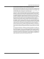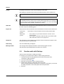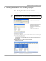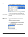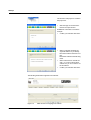
1
AUTOMATION
User manual
UM QS EN STARTUP+
Order No.: —
Handling an Axioline station under Startup+
AUTOMATION
User manual
Handling an Axioline station under Startup+
2011-05-24
Designation:
UM QS EN STARTUP+
Revision:
01
Order No.:
—
This user manual is valid for:
Designation
Revision
Order No.
Startup+
2.00 or later
2700636
8197_en_01
PHOENIX CONTACT
Please observe the following notes
Please observe the following notes
In order to ensure the safe use of the product described, you have to read and understand
this manual. The following notes provide information on how to use this user manual.
User group of this manual
The use of products described in this manual is oriented exclusively to qualified electricians
or persons instructed by them, who are familiar with applicable national standards and other
regulations regarding electrical engineering and, in particular, the relevant safety concepts.
Phoenix Contact accepts no liability for erroneous handling or damage to products from
Phoenix Contact or third-party products resulting from disregard of information contained in
this user manual.
Explanation of symbols used and signal words
This is the safety alert symbol. It is used to alert you to potential personal injury
hazards. Obey all safety measures that follow this symbol to avoid possible injury or death.
DANGER
This indicates a hazardous situation which, if not avoided, will result in death or serious
injury.
WARNING
This indicates a hazardous situation which, if not avoided, could result in death or serious
injury.
CAUTION
This indicates a hazardous situation which, if not avoided, could result in minor or moderate injury.
The following types of messages provide information about possible property damage and
general information concerning proper operation and ease-of-use.
NOTE
This symbol and the accompanying text alert the reader to a situation which may cause
damage or malfunction to the device, hardware or software, or surrounding property.
This symbol and the accompanying text provide the reader with additional information,
such as tips and advice on the efficient use of hardware and on software optimization. It
is also used as a reference to other sources of information (manuals, data sheets) on the
subject matter, product, etc.
PHOENIX CONTACT
Please observe the following notes
General terms and conditions of use for technical documentation
Phoenix Contact reserves the right to alter, correct, and/or improve the technical documentation and the products described in the technical documentation at its own discretion and
without giving prior notice, insofar as this is reasonable for the user. The same applies to any
technical changes that serve the purpose of technical progress.
The receipt of technical documentation (in particular data sheets, installation instructions,
manuals, etc.) does not constitute any further duty on the part of Phoenix Contact to furnish
information on alterations to products and/or technical documentation. Any other agreement shall only apply if expressly confirmed in writing by Phoenix Contact. Please note that
the supplied documentation is product-specific documentation only and that you are responsible for checking the suitability and intended use of the products in your specific application, in particular with regard to observing the applicable standards and regulations. Although Phoenix Contact makes every effort to ensure that the information content is
accurate, up-to-date, and state-of-the-art, technical inaccuracies and/or printing errors in
the information cannot be ruled out. Phoenix Contact does not offer any guarantees as to
the reliability, accuracy or completeness of the information. All information made available
in the technical data is supplied without any accompanying guarantee, whether expressly
mentioned, implied or tacitly assumed. This information does not include any guarantees regarding quality, does not describe any fair marketable quality, and does not make any
claims as to quality guarantees or guarantees regarding the suitability for a special purpose.
Phoenix Contact accepts no liability or responsibility for errors or omissions in the content
of the technical documentation (in particular data sheets, installation instructions, manuals,
etc.).
The aforementioned limitations of liability and exemptions from liability do not apply, in so
far as liability must be assumed, e.g., according to product liability law, in cases of premeditation, gross negligence, on account of loss of life, physical injury or damage to health or on
account of the violation of important contractual obligations. Claims for damages for the violation of important contractual obligations are, however, limited to contract-typical, predictable damages, provided there is no premeditation or gross negligence, or that liability is assumed on account of loss of life, physical injury or damage to health. This ruling does not
imply a change in the burden of proof to the detriment of the user.
PHOENIX CONTACT
Please observe the following notes
Statement of legal authority
This manual, including all illustrations contained herein, is copyright protected. Use of this
manual by any third party is forbidden. Reproduction, translation, and public disclosure, as
well as electronic and photographic archiving and modification require written consent
by Phoenix Contact. Violators are liable for damages.
Phoenix Contact reserves all rights in the case of patent award or listing of a registered design. Third-party products are always named without reference to patent rights. The existence of such rights shall not be excluded.
How to contact us
Internet
Up-to-date information on Phoenix Contact products and our Terms and Conditions can be
found on the Internet at:
www.phoenixcontact.com.
Make sure you always use the latest documentation.
It can be downloaded at:
www.phoenixcontact.net/catalog.
Subsidiaries
If there are any problems that cannot be solved using the documentation, please contact
your Phoenix Contact subsidiary.
Subsidiary contact information is available at www.phoenixcontact.com.
Published by
PHOENIX CONTACT GmbH & Co. KG
Flachsmarktstraße 8
32825 Blomberg
GERMANY
Phone
+49 - (0) 52 35 - 3-00
Telefax
+49 - (0) 52 35 - 3-4 12 00
PHOENIX CONTACT
P.O. Box 4100
Harrisburg, PA 17111-0100
USA
Phone
+1-717-944-1300
Should you have any suggestions or recommendations for improvement of the contents and
layout of our manuals, please send your comments to:
[email protected]
PHOENIX CONTACT
Table of contents
1
2
3
4
Basics and example project.....................................................................................................1-1
1.1
Information about this document ........................................................................ 1-1
1.2
Startup+ software ............................................................................................... 1-1
1.3
Requirements ..................................................................................................... 1-1
1.4
Required Axioline module versions .................................................................... 1-2
1.5
Wiring the hardware, applying voltage................................................................ 1-2
1.6
Installing the software ......................................................................................... 1-2
Startup+: Online help, user interface and function calls ...........................................................2-1
2.1
Online help ......................................................................................................... 2-1
2.2
The Startup+ user interface ................................................................................ 2-1
2.3
Function calls with Startup+................................................................................ 2-2
Starting the software and creating a project.............................................................................3-1
3.1
Starting the software for the first time.................................................................. 3-1
3.2
Starting the software for the second time and every further start ........................ 3-2
3.3
Axioline assistant................................................................................................ 3-3
Parameterization, diagnostics and I/O check...........................................................................4-1
8197_en_01
4.1
Parameterization ................................................................................................ 4-1
4.2
Diagnostics......................................................................................................... 4-4
4.3
I/O check ............................................................................................................ 4-5
4.3.1
Digital input/output modules ................................................................ 4-5
4.3.2
Analog input/output modules .............................................................. 4-6
4.3.3
Logging process data ......................................................................... 4-7
PHOENIX CONTACT
i
Startup+
ii
PHOENIX CONTACT
8197_en_01
Basics and example project
1
Basics and example project
1.1
Information about this document
This document describes the functions of the Startup+ software with an example project.
1.2
Startup+ software
Startup+ is a software for easy wiring checks.
It offers the following functions:
– Parameterization of the Axioline modules of a station
– I/O check
– Diagnostics
Startup+ allows you to establish a connection to an Axioline station quickly and easily in
order to check the wiring of this station. In addition to the basic functions mentioned above,
it is also possible with the Startup+ software to assign a device name and an IP address to
a bus coupler, as well as to record the writing and reading of process data in a file during the
I/O check for a better documentation.
1.3
Requirements
Knowledge
It is assumed the user has knowledge and experience in the operation of PCs and Windows
operating systems.
Hardware
In order to be able to start up the example system, the following hardware is required:
– Programming device/PC
– PC Pentium III with at least 1 GHz, 512 MB RAM and 50 MB free hard disk space
– Windows XP SP2 or Windows 2000 SP4
– Microsoft.NET Framework 2.0
Microsoft.NET Framework 2.0 can be downloaded free of charge from the Microsoft homepage.
– Axioline station (e.g., AXL STARTERKIT)
– Ethernet connection from the Axioline station to the programming device/PC
8197_en_01
PHOENIX CONTACT
1-1
Startup+
1.4
Required Axioline module versions
The following hardware and firmware versions of the Axioline modules are required to use
the software functions:
Table 1-1
Axioline module versions for use under Startup+
Type
Order No.
Hardware
AXL BK PN
2688019
01
1.10
AXL DI 16/4
2688022
01
--
AXL DI 32/1
2688035
01
--
AXL DO 16/3
2688048
01
--
AXL AI 8
2688064
02
1.21
AXL AO 8
2688080
01
1.20
AXL RTD 8
2688077
03
1.20
00
00
Other
1.5
•
Firmware
Wiring the hardware, applying voltage
Wire the Axioline station, establish an Ethernet connection to the PC, and supply voltage to your system.
70
71
72
73
74
75
76
77
60
61
62
63
64
65
66
67
50
51
52
53
54
55
56
57
40 41
70 71
60 61
50 51
40 41
42 43
72 73
62 63
52 53
42 43
44 45
74 75
64 65
54 55
44 45
AXL STARTERKIT
(2688284)
46 47
76 77
66 67
56 57
46 47
X1
PC
Startup+
Table 1-2
a1
00 01
10 11
20 21
30 31
00 01
a1
00 01
10 11
20 21
30 31
00 01
a2
10
11
12
13
14
15
16
17
a2
10
11
12
13
14
15
16
17
b1
20
21
22
23
24
25
26
27
b1
20
21
22
23
24
25
26
27
b2
30
31
32
33
34
35
36
37
b2
30
31
32
33
34
35
36
37
D
UI
E
02 03
12 13
22 23
32 33
02 03
04 05
14 15
24 25
34 35
04 05
06 07
16 17
26 27
36 37
06 07
D
UO
E1
02 03
12 13
22 23
32 33
02 03
04 05
14 15
24 25
34 35
04 05
06 07
16 17
26 27
36 37
06 07
AXL DO 16/3
UL+ AXL BK PN
AXL DI 32/1
Wired example system
81970001
NOTE:
Please observe the data sheets for the modules used when you wire the example system.
1.6
Installing the software
The software can be downloaded free of charge at www.phoenixcontact.com.
• Install the software.
To do this execute the file StartupPlusSetup.exe.
Then follow the installation instructions.
1-2
PHOENIX CONTACT
8197_en_01
Startup+: Online help, user interface and function calls
2
Startup+: Online help, user interface and function calls
2.1
Online help
A comprehensive online help is available. How to call the online help:
• Select the menu item "?, Help".The table of contents for the online help appears.
Search for a help topic as described below.
Or
• In an active dialog box or window, press <F1>.
The context-sensitive online help for the active input mask or the active window appears.
In device-specific input masks there may be an additional button or a symbol for calling
the online help.
2.2
The Startup+ user interface
The interface is divided into the following areas:
1
2
3
4
Menu bar
Toolbar
Status bar
Project tree
5
6
7
Workspace
DTM catalog
Message window
1
2
4
5
6
7
3
Table 2-1
Menu bar
User interface
Appearance and functioning of the menus corresponds to the Windows standard.
Additional commands can be found in the various context menus such as, for example, in
the context menu of a DTM in the project tree, in the context menu of a window or the context
menu of a message window.
The menu commands can also be called via the toolbar or by means of shortcuts.
8197_en_01
PHOENIX CONTACT
2-1
Startup+
Toolbar
Frequently used functions can be accessed quickly via the toolbar.
The meaning of a symbol is shown when you position the mouse cursor over the icon.
You will find a detailed description of all symbols with their functions in the online help.
The following applies for the menu bar as well as for the tool bar:
The available menu items depend on the currently marked object that you are working on.
The color of the icon shows whether the menu item is available or not. The icon is shown
in gray if the menu item is disabled - otherwise it is colored.
Status bar
The status line shows a progress bar, status information in the form of text messages and
the name of the user currently logged in.
Project tree
The project tree shows the structure of the communication connections of the field devices.
Green background:
The module is connected and the user has actively worked with it.
White background:
–
–
The module is not yet connected when the "Connect" icon is
shown in green.
The module is connected, but the user has not yet worked online
with it, when the "Connect" icon is grayed out.
Workspace
The workspace is used to display the "Properties" window and the device-specific screen
masks provided by the respective DTM.
DTM catalog
The current DTM catalog is displayed.
Message window
The message window displays information on the internal program execution.
This information may be helpful when errors have to be removed.
2.3
Function calls with Startup+
There are often several ways of calling up a function.
For example, you could proceed as follows to call the online parameters:
1. Context menu of the module (right-click on the module in the project tree):
"Parameters, Online Parameter"
2. Icon in the command line:
3. Menu bar of the program: "Device, Online Parameter"
4. Double-click on the entry of the module in the project tree.
This opens offline parameters. When there is a connection to the module, you can send
the offline parameters to the module just like the online parameters.
5. Shortcuts
2-2
PHOENIX CONTACT
8197_en_01
Starting the software and creating a project
3
Starting the software and creating a project
3.1
•
Starting the software for the first time
Start the software. To do this select "Start, Programs, Phoenix Contact, Startup+,
Startup+".
Startup+ will be started in English. If you want to change the language, please follow the
first steps listed below and change the language when you are requested to do so in the
documentation.
•
Confirm this window with "OK".
•
Define the user roles when you start
the software for the first time.
Define at least one user as an administrator.
Confirm your entry with "OK".
•
DTM Catalog Management
The DTM catalog of the Axioline modules is installed with the software. In the following add
these Axioline DTMs to the software.
• Then search for installed DTMs.
Click the "Search for installed DTMs" button in the "DTM Catalog Management" window that opens.
All DTMs installed on the PC will be shown as known DTMs.
• Select the Axioline DTMs.
Figure 3-1
8197_en_01
Installed DTMs; Axioline DTMs are selected
PHOENIX CONTACT
3-1
Startup+
•
Transfer the Axioline DTMs in the current catalog by clicking the
Figure 3-2
•
Option: Transferring further DTMs
button.
Axioline DTMs transferred into the current catalog
Confirm the selection by clicking the "Update Catalog and Close Window" button.
You have now transferred all available Axioline DTMs into the software. If additional DTMs
are available at a later time, transfer these as well. To do this select the "Tools, DTM Catalog
Management" menu.
The Axioline assistant opens after you have closed the DTM Catalog Management window.
If you do not want to change the language follow the description from "Axioline assistant" on
page 3-3 and onwards.
Option:
Changing the language
•
•
•
•
If you want to change the language, stop the Axioline assistant with "Cancel".
Select the "Tools, Options, Internal Settings" menu in the menu bar and select the language.
Confirm your selection with "OK".
Start the program again to activate the language selection.
3.2
Starting the software for the second time and
every further start
If you start the software for the second time you are prompted to log in as a user.
Figure 3-3
•
3-2
PHOENIX CONTACT
User login
Please enter the user name under "Name".
8197_en_01
Starting the software and creating a project
There are two options for the password entry:
1. Enter a password.
This password will be requested for every further start of the program.
Or:
2. Activate the "Use Windows login for this user" checkbox.
In this case the password will not be requested for every further start of the program.
The Axioline assistant will start after the authentication.
3.3
Axioline assistant
The Axioline assistant opens.
•
•
Load an existing project or create a
new project.
Confirm your selection with "Next".
Load an existing project
•
If a project has already been created, select this project and confirm the selection with
"Finish“.
Create a new project
•
Select the "Create new project" to create a new project.
•
Select the connected bus coupler
type.
The AXL BK PN bus coupler is used in
the example, therefore select the PROFINET device type.
• Confirm your selection with "Next".
8197_en_01
PHOENIX CONTACT
3-3
Startup+
The structure of the project is created in
the project tree.
•
Select the type of connection between bus coupler and PC.
An Ethernet connection is used in the
example.
• Confirm your selection with "Next".
•
•
•
Select "Configure an already assigned IP address" if you already
know the IP address of the bus coupler.
Enter the IP address in the following
mask.
Select "Find device in TCP/IP network..." if you do not know the IP
address or if you do not want to enter the address.
Confirm your selection with "Next".
The following main window appears in the software:
Figure 3-4
3-4
PHOENIX CONTACT
Main window for assigning an IP address
8197_en_01
Starting the software and creating a project
•
•
Select the network card of your connection under "Network Adapter".
Click on the "Refresh" button.
The current settings of the bus coupler will be displayed.
Figure 3-5
•
•
•
IP address of the bus coupler
Change the settings if required.
Apply the settings with "Apply".
Confirm the settings with "OK".
The connected bus is determined.
• Confirm the window with "Next".
•
Confirm the window with
"Continue".
The connected bus will be shown.
• Select the compatible DTMs either
automatically or manually.
• Confirm the window with
"Continue".
The topology has been scanned.
• Accept the topology with "Finish".
• The following window shows all
steps that have been carried out.
Exit this window with "Finish".
The Axioline station is displayed in the
project tree.
8197_en_01
PHOENIX CONTACT
3-5
Startup+
You have now created your new project and you are already connected with the bus coupler.
• Save the project.
3-6
PHOENIX CONTACT
8197_en_01
Parameterization, diagnostics and I/O check
4
Parameterization, diagnostics and I/O check
4.1
Parameterization
You can read the parameterization and change it online or offline.
• Establish the connection to the device.
Select "Device, Connect" or .
• Upload the parameters from the device.
Select "Device, Parameter Upload" or
.
Since you are now working actively on the device, it is shown with a green background in
the project tree.
Figure 4-1
•
Active connection to the device
You can parameterize the device now.
For example, select "Device, Online Parameter" or
.
The window with the parameters opens. Different information may be displayed depending
on the module.
Identification
The device rating plate is shown under "Parameter Menu, ..., Identification".
Figure 4-2
•
•
8197_en_01
Parameters for identification
Adapt these entries, if necessary.
Confirm your entries with "Apply".
The parameterization will be sent to the module.
Then confirm with "OK".
PHOENIX CONTACT
4-1
Startup+
•
Answer the following question.
Figure 4-3
Read back parameter record?
If you answer the question with "Yes", the changes will also be transferred to the offline project data.
If you answer the question with "No", the changes will not be transferred to the offline project
data.. In this case online and offline project data will be different.
The window will be closed after you have answered the question.
Parameters
4-2
PHOENIX CONTACT
•
If a module can be parameterized, the current parameterization will be shown under
"Parameter Menu, Parameters, Parameters".
Figure 4-4
Parameterization
Figure 4-5
Parameterization of an analog module (not included in the example configuration)
8197_en_01
Parameterization, diagnostics and I/O check
•
•
•
Adapt the parameterization, if necessary.
Confirm your entries with "Apply".
The parameterization will be sent to the module.
Then confirm with "OK".
Answer the following question.
Figure 4-6
Read back parameter record?
If you answer the question with "Yes", the changes will also be transferred to the offline project data.
If you answer the question with "No", the changes will not be transferred to the offline project
data.. In this case online and offline project data will be different.
The window will be closed after you have answered the question.
Not transmitted changes
Changes that have not yet been transmitted are indicated with a pen in the "Status" column
as well as in the status line.
Figure 4-7
8197_en_01
Not transmitted changes
PHOENIX CONTACT
4-3
Startup+
4.2
Diagnostics
The status of the station and the individual devices can be monitored best on the entry of
the bus coupler.
• Double-click on the bus coupler entry in the project tree. This opens the diagnostics
window.
Figure 4-8
Diagnostics: OK
Figure 4-9
Diagnostics: An error has occurred
•
The error cause will be displayed when you switch to the module concerned under
"slot".
Figure 4-10
•
4-4
PHOENIX CONTACT
Diagnostics: Error cause
You can also call the diagnostics function on the individual modules.
To do this, select the entry of the device.
Select "Device, Diagnostics" or
.
8197_en_01
Parameterization, diagnostics and I/O check
4.3
•
•
I/O check
On a connected module select the I/O Check function by right-clicking the "Functions,
IO Check" entry in the context menu of the module.
In the window that appears, click the "Refresh on" button.
The current process data of the module is displayed in the window.
For output modules you can specify the output values.
When you change the output on a module for the first time you will be prompted to confirm
the action.
Figure 4-11
•
Write process data?
Confirm this question with "OK".
4.3.1
Figure 4-12
Digital input/output modules
IO check of a digital module (Example: AXL DO 16/3)
For output modules you can click on an output to set this output.
• Click on an output.
On a permissible terminal point the mouse cursor changes into a hand.
The output is set. You can now set or reset more outputs. The last status is retained when
you switch off the refresh and when you close the window.
8197_en_01
PHOENIX CONTACT
4-5
Startup+
4.3.2
•
Analog input/output modules
Activate the inputs or outputs that you want to monitor in the "Diagram" column.
Under "Signal description" the writing of the input or output is specified.
The window shows the current process data of the module as a value and in the diagram.
The process data is shown in the diagram and logged on demand in the log file only for
the inputs or outputs that have been selected under "Diagram".
For output modules: You can change the process data for all outputs. It is transferred to
the module no matter whether the output has been selected under "Diagram" or not.
Figure 4-13
IO check of an analog module (Example: AXL AO 8)
For output modules you can change each output by entering a value in the left-hand column
"Process value" or modify it in the right-hand column "Process value" by changing the position of the slider.
• Change the process value by specifying the value or changing the position of the slider.
• Complete the action by clicking anywhere else. Only then will the new value be accepted.
The output is set accordingly. You can specify more output values now. The last status is
retained when you switch off the refresh and when you close the window.
4-6
PHOENIX CONTACT
8197_en_01
Parameterization, diagnostics and I/O check
4.3.3
Logging process data
For every module you can log the process data for up to five minutes.
• Activate the checkbox in the window for the I/O check for this.
Figure 4-14
•
Logging process data
Click the "Refresh on" button.
The data is logged (up to five minutes) until you press the "Refresh off" button.
Figure 4-15
8197_en_01
Logged process data
PHOENIX CONTACT
4-7
Startup+
4-8
PHOENIX CONTACT
8197_en_01