1
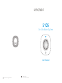
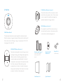
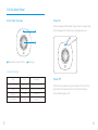
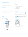
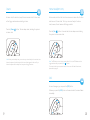
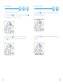
S105
On-Site Alarm System
User Manual
2014 smanos. All rights reserved.
Printed in China
PA: OI-S105-EN-1404-V1.0
Table of Contents
Working Mode
Product Introduction
1~4
Test the PIR Motion Detector
Install the PIR Motion Detector
Foreword
Installation Notices
Features
Connecting and Deleting Accessories
In the Box
On-Site Alarm Panel
5~6
Pairing the Remote Control
Pairing the Door/Window Contact
Alarm Panel Overview
Pairing the PIR Motion Detector
Power On
Deleting Accessories
Power Off
Test and Install Accessories
Remote Control
26~28
7~25
Zone Setting For Wireless Accessories
29
Entry and Exit Delay
30
Act as an Accessories Kit
31~32
Overview
Arm(Away Arm)
Pairing the Siren to the Control Panel
Disarm
Pairing Other Wireless Detector to the Control Panel
Home Mode (Part Arm)
Deleting the Siren from the Control Panel
SOS
Deleting Accessories from the Control Panel
Mute Operation
Nightlight On/Off
Test and Install the Door/Window Contact
Overview
Test the Door/Window Contact
Install the Door/Window Contact
Test and Install the PIR Motion Detector
Overview
Specifications
33~36
Disclaimer
37
Caution and Warnings
38
Terms of Warranty
39
Notes
40
Product Introduction
Foreword
Features
Dear Customers:
100% wireless configuration, easy to use
Thank you for purchasing S105. This product is a totally plug & play
Compact and streamline design
wireless home security solution. It features automatic pairing to
One-button pairing
various accessories, putting your home under all-round protection.
Work as accessory or standalone alarm panel
To experience this wonderful product, please follow the instructions
Built-in battery for 8-hour standby
in the user manual.
Mute operation
Nightlight function
Support 40 wireless accessories (including remote control)
Built-in 1,000,000 RF codes combination maintains high reliability
Please read this manual carefully before using.
Please kindly keep this user manual for your reference when necessary.
1
2
In the Box
DS2300 Door/Window Contact x 1
The contact can be used for doors, windows, or other
devices that can be opened or closed. Once a window
or door is opened (the transmitter and magnet are
separated), thesystem will trigger an alarm.
RE2300 Remote Control x 2
It's convenient to carry. With the remote control, you
can arm/disarm the system, set home mode, perform
SS1005 Alarm Panel x 1
mute arm/disarm, make an emergency call.
The alarm panel receives and processes signals from wireless accessories.
When the accessory is triggered, the panel will alarm and the strobe light will
flash to deter intruders. With plug-in design, it is powered by AC 100~240V
by plugging it into a wall outlet.
MD2300 PIR Motion Detector x 1
The detector adopts digital dual-core fuzzy logic control
processing technology and intelligent analysis algorithm,
effective resolution of interfering signal and human
Double-sided Tape x 4
(2pcs for door/window
contact, 2pcs for PIR
sensor )
Bracket for PIR
Detector x 1
Screw Kit x 1
(For PIR sensor)
movement signal, preventing false alarm. It can detect
the temperature and movement of human bodies within
the 8-meter cone space. When detecting human
movement twice in 3 minutes, it switches to the powersaving mode automatically. After 3 minutes of no human
movement, it switches to the working state.
User Manual x 1
3
Quick Guide x 1
4
On-Site Alarm Panel
Alarm Panel Overview
Power On
The siren is powered off by default. Plug the siren into a power outlet.
Press the power button. It beeps once, indicating power is on.
Power button/connect button
Strobe light
Siren and Strobe Light
5
Power Off
Status
Siren
Strobe Light
Arm or Home Arm
Beeps once
Flashes once and then on
After the siren is powered on, press the power button once. Then,
Disarm
Beeps twice
Flashes twice and then off
press and hold the power button for 6 seconds until a beep is
Mute Arm
No beep
Lights on
Mute Disarm
No beep
Lights off
heard, indicating power is off.
6
Test and Install Accessories
LED Indication
Accessories in this kit can work only with our control panels.
LED blinks once: Armed or in home mode
Remote Control
LED blinks once: Disarmed
RE2300 remote control is dainty and delicate, easy to carry. It can be attached
LEDs blinks once: SOS
to your key ring, or just put into your pockets or purses. When you are about
to exit or entry the house, you can use it to arm or disarm the system. In case
of any emergency, just press the [SOS] button, the alarm will be activated
Arm(Away Arm)
immediately.
In arm state, the system will trigger an alarm when detecting intrusion.
Overview
Press the [Arm
] button. The siren beeps once, indicating the system is in
the arm state.
LED Indicator
Arm
Guide Point For
The Blind
Disarm
Stay
Note: If you do not want to take the remote control, entry and exit delay time can be set.
For related definition and setting, please refer to page 29.
SOS
Metal Ring
7
8
Disarm
Home Mode(Part Arm)
In disarm state, the detectors (except those accessories in the 24-hour zone)
In home mode, detectors that set in home zone are in disarm state; the other
will not trigger an alarm when detecting intrusion.
detectors are still in arm state. That is, you can move freely in the home
zone; however, the rest areas are still being protected.
Press the [Disarm
] button. The siren beeps twice, indicating the system is
in disarm state.
Note: If entry and exit delay is set, you can enter your home directly in the arm state, then
disarm the system within the delay time. No alarm will be triggered in this case. If you
disarm the system after the delay time, the system will trigger an alarm.
Press the [Stay
] button. 3 seconds later, the siren beeps once indicating
the system is in home mode state.
Note: The PIR detector is set in home zone by default. That is, the PIR detector will not
trigger an alarm after you press the [Stay
] button.
The zones include home zone, normal zone, 24-hour zone. For details of each zone,
please refer to page 30.
SOS
In case of emergency, you can press the [SOS] button.
Whenever you press the [SOS] button on the remote control, the siren will alarm
immediately.
9
10
Mute Operation
Nightlight On/Off
You can arm and disarm the system silently.
Press and hold the [Stay
] button for 1 second, and then press the [Arm
]
] button twice, the siren switches to home mode
Press the [Stay
silently and the nightlight is on.
button within 3 seconds. The system is armed silently.
Press and hold the [Stay
[Disarm
11
] button for 1 second, and then press the
] button within 3 seconds. The system is disarmed silently.
Press the [Disarm
nightlight.
] button, the siren disarms and switches off the
12
PCB Layout
Test and Install the Door/Window Contact
The contact contains a transmitter and a magnet, which can be mounted on
a door, window, or any object that can be opened or closed. When the
transmitter and magnet are separated, or the tamper switch is pressed, the
system will trigger an alarm.
Tamper Switch
CR2032 Lithium
Cell Battery
Overview
LED Indicator
Test the Door/Window Contact
Tamper Switch
This is to test whether the contact can work properly.
Transmitter
Magnet
1. Remove the insulating strip
Front side
Back side
The contact works immediately.
LED Indication
Blinks once: Intruder is detected.
Blinks once per 3 seconds after triggered: Low battery. Replace the battery as
soon as possible.
13
14
2. Pay attention to the direction
Install the Door/Window Contact
There are triangle marks on the side of the transmitter and magnet. Make sure
the triangle marks is close to each other and within the range of 1 cm.
Make sure the triangle marks on the side of the transmitter and magnet are
close to each other and within the range of 1 cm when installing.
Secure the contact with double-sided tapes
Secure the transmitter and magnet on the desired locations with double-sided
tapes.
3. Test the door/window contact
Press the [Arm
] button. The system switches to the arm state. Separate the
transmitter and magnet with the space more than 2 cm. The LED on the
transmitter blinks once, then the siren alarms. This means the contact works
properly.
>2cm
Note: If this product is installed on
metal door, place spacers under the
transmitter and magnet.
This product is not suitable for shutter
door, please purchase shutter door
sensor for your use.
1
15
2
16
PCB Layout
Test and Install the PIR Motion Detector
The detector adopts digital dual-core fuzzy logic control processing
Tamper Switch
technology and intelligent analysis algorithm, effective resolution of
Infrared Sensor
interfering signal and human movement signal, preventing false alarm. It
features automatic temperature compensation and resistance to flow
technology, adapting to environmental and temperature change. It can
detect human movement within the 8-meter cone space, suitable for halls,
hallways, etc.
LED Indicator
Overview
Note: When tamper switch is triggered, the siren will alarm immediately.
Test Button
Detection
Lens
Double-sided
Tape Stick Place
Working Mode
Testing Mode
After self-testing, press the test button, the detector switches to the testing
LED Indicator
Bracket Slot
mode and detects once every 10 seconds. It triggers an alarm. After 3
minutes, the LED blinks twice, and the detector switches to the power-saving
mode.
LED Indication
Blinks continuously: Self-testing.
Blinks once: Intrusion is detected.
Blinks twice: 3 minutes testing mode is finished, enters power saving mode.
Blinks once per 3 seconds: Low battery indication, please change the
batteries immediately.
17
18
Power-Saving Mode
Test the PIR Motion Detector
The product features power-saving design. If the detector detects human
movement twice in 3 minutes, it will switch to the sleeping state to save power.
At this time, the LED will not blink and no alarm. After no movement within the
next 3 minutes, the detector switches back to the working state automatically.
This is to test whether the PIR detector works normally.
1. Remove the insulating strip
Remove the insulating strip.
Case 1:
Initial start and then guard.
Case 2:
Press the test button and then guard.
2. Arm the system
Press the [Arm
] button on the
remote control. The system is armed.
3 minutes later
Sleep after detecting human
movement twice
No human movement
within 3 minutes
Switch from sleep to guard.
3. Trigger an alarm
Note: After the detector is in the sleeping state, ensure no human movement within 3
minutes; otherwise, the detector remains sleeping.
In the sleeping state, it is recommended that you leave the room after arming the system.
Ensure no human movement in 3 minutes. Then, go into the room, the siren alarms
Keep pressing the test button at the back until the siren sounds. It indicates
that the PIR motion detector is connected to the siren.
immediately.
Detection Scope
0m
2m
4m
6m
8m
2m
Top view
110°
0m
Side view
19
20
3. Test the PIR motion detector
Install the PIR Motion Detector
Press the test button at the back. It switches to the testing mode and sustains
After making sure the detector works normally, do as follows:
for 3 minutes. Walk in the detection scope and observe the LED. When
human movement is detected, the LED blinks once.
1. Choose a suitable installation location
It is recommended to mount it at the height of 2m from the ground.
For installation notices, please see page 23-25.
2m
4. Adjust the angle
Adjust the bracket angle to achieve the best detection effect.
2. Fix the detector
Fix the installation bracket on the wall with screws, and then fit the groove at
the back of the detector on the bracket. For the detector of this model, you
can stick it at the corner with double-sided tapes.
Side view
21
1
2
Top view
22
Installation Notices
Mount the detector in a proper angle
Pay attention to the following during installation:
The installation angle affects sensitivity directly. The sensitivity is
optimal when the walk direction is vertical to the infrared direction.
Choose the best location and angle according to the actual situation
and detection scope diagram.
Mount the detector to a location close to the entry or exit
The detector aims at preventing intrusion. Detecting human movement at the
entry or exit is critical for security.
Avoid facing to glass windows or doors
Strong light interferes with detection sensitivity. In addition, complicated
situations, such as traffic flow, stream of people, also should be avoided.
23
24
Connecting and Deleting Accessories
Avoid facing to or positioning close to heat/cold sources
Heat/cold sources, such as heat extraction units, heaters, air conditioner,
microwave oven, refrigerator, which may cause false triggering, should be
Accessories need to be paired to the siren so that the siren can
receive signals from them, and sound the alarm. Accessories in the
kit have been paired to the siren before delivery, and ready for use.
If the siren does not alarm when detectors are triggered, please pair
them again. Accessories purchased separately must be paired to the
siren before use.
avoided.
ON
Pairing the Remote Control
1
Press the connect button on the siren
Press the connect button on the siren, it beeps once, 3 seconds
later, it beeps once again and the strobe flashes, indicating the siren
is ready for pairing.
2
Press any button on the remote control
Press any button on the remote control, the siren beeps once,
indicating successful pairing.
Avoid facing to swinging objects
Swinging objects may also trigger false triggering. Besides, if there are two
detectors covering the save scope, adjust the locations to prevent
cross-interference.
Note: If the siren beeps twice, it indicates the remote control has been paired before.
25
26
Pairing the Door/Window Contact
Pairing the PIR Motion Detector
1
Press the connect button on the siren
Press the connect button on the siren, it beeps once, 3 seconds
later, it beeps once again and the strobe flashes, indicating the siren
is ready for pairing.
2
Separate the transmitter and magnet
Make sure the triangle marks close to each other and within the
range of 1cm, and then separate them with the space more than 2
cm. The siren beeps once indicates successful pairing.
1
Press the connect button on the siren
Press the connect button on the siren, it beeps once, 3 seconds
later, it beeps once again and the strobe flashes, indicating the siren
is ready for pairing.
2
Press the test button on the PIR motion detector
Press the test button at the back of the PIR motion detector. The
siren beeps once, indicating successful pairing.
>2cm
Note: If the siren beeps twice, it indicates the PIR motion detector has been paired
before.
Note: If the siren beeps twice, it indicates the door/window contact has been paired
before.
Deleting Accessories
Deleting accessories is to disconnect accessories from the siren.
After that, the siren cannot receive signals from accessories nor
trigger alarms.
Press and hold the connect button on the siren for 6 seconds, the
siren beeps once and the strobe flashes twice, indicating all the
accessories are deleted.
27
28
Zone Mode of Wireless Accessories
Entry and Exit Delay
The zone mode of wireless accessory includes: normal zone,
If you do not want to take the remote control, entry and exit delay
time can be set.
home mode zone or 24-H zone.
Normal Zone: In arm or home mode status, the system will alarm
immediately once the sensors in normal zone is triggered.
Home Mode Zone: In home mode status, the system will not
alarm once the sensor in home mode zone is triggered.
24-H Zone: In any condition, the system will alarm immediately
once the 24-H zone detector is triggered.
Sensor
Default Zone
MD2300 PIR Motion Detector
Home Mode Zone
DS2300 Door/Window Contact
Normal Zone
Note: The default zone setting of smoke detector, gas detector or outdoor
beam sensors are 24-H zone.
29
Press the connect button twice, delaying for 30 seconds.
Press the connect button for three times, delaying for 60 seconds.
Press the connect button for four times, disabling the function.
After setup, if you arm the system, the siren beeps once every 5
seconds until it goes to arm state. If the sensors are triggered, the
siren will sound the alarm after the delay time.
Note: Press the [Arm ] button on the remote control twice. The system
switches to arm state immediately.
30
Act as an Accessory Kit
Pairing Other Wireless Detectors to the Control Panel
If user purchased our alarm system before, S105 can act as an
accessory kit, working with the control panel after successful pairing.
After control panel enters its pairing status (please refer to its user
manual), trigger the wireless detector, the control panel beeps once
to indicate successfully pairing.
Pairing the Siren to the Control Panel
1
Press the connect button on the siren
Press the connect button on the siren, it beeps once, 3 seconds
later, it beeps once again and the strobe flashes, indicating the siren
is ready for pairing.
2
Press the [Arm] or [SOS] button on the control Panel
Press the [Arm ] or [SOS] button on the control panel, the siren
beeps once, indicating successful pairing.
Deleting the Siren from the Control Panel
Press and hold the connect button on the siren for 6 seconds. The
siren beeps once and the strobe flashes twice, the siren is deleted
from the control panel.
Deleting Accessories from the Control Panel
Please refer to the manual of control panel.
Exit the pairing status
Press the connect button on the siren, it beeps once, exiting the
pairing status.
Test whether the siren has been paired
Press the [Arm ] button on the remote control. If the siren and
control panel both beep once, it indicates the pairing succeeds. If
not, please pair them again.
31
32
Specifications
SS1005 On-Site Alarm Panel / Mini Strobe Siren
RE2300 Remote Control
Power Supply
Power Supply
AC 100V~240V, 50/60 Hz
DC 3V(CR2032 lithium cell battery x 1)
Volume
Transmit Current
90dB
≤ 9.5 mA
Backup Battery
Transmitting Distance
3.7V 600mAh lithium battery
≤ 80 m (open area/no interference)
Static Current
Radio Frequency
≤ 13mA
868MHz
Alarm Current
Housing Material
≤ 100mA
PC+ABS plastic
Radio Frequency
Operating Condition
868MHz
Temperature -10℃~+55℃
Housing Material
Relative Humidity ≤ 80% (non-condensing)
PC+ABS plastic
Dimensions ( L x W x H )
Operating Condition
71 x 38 x 12 mm
Temperature -10°C ~ +55°C
Relative Humidity ≤ 80% (non-condensing)
Dimensions ( L x W x H )
90 x 90 x 42.2mm (Not include plug part)
33
34
DS2300 Door/Window Contact
MD2300 PIR Motion Detector
Power Supply
Power Supply
DC 3V(CR2032 lithium cell battery x 2)
DC 3V(1.5V AA battery x 2)
Static Current
Static Current
≤ 1 uA
≤ 50 uA
Alarm Current
Alarm Current
≤ 10.5 mA
≤ 11 mA
Transmitting Distance
Detection Scope
≤ 80 m (open area/no interference)
8m/110°
Radio Frequency
Transmitting Distance
868MHz
≤ 80 m (open area/no interference)
Housing Material
Radio Frequency
ABS plastic
868MHz
Operating Condition
Housing Material
Temperature -10℃~+55℃
ABS plastic
Relative Humidity ≤ 80% (non-condensing)
Operating Condition
Transmitter Dimensions ( L x W x H )
Temperature
72.5 x 28 x 10 mm
Relative Humidity ≤ 80% (non-condensing)
-10℃~+55℃
Magnet Dimensions ( L x W x H )
Detector Dimensions ( L x W x H )
58 x 14 x 9.5 mm
101.5 x 59 x 37.5 mm
Bracket Dimensions ( L x W x H )
60 x 29 x 27 mm
35
36
Disclaimer
Caution and Warnings
smanos have reviewed this manual thoroughly in order to make it an easy to
Due to laws and regulations determined by the Euopean Parliament, some
use guide for this product. All statements, technical information,
(wireless) devices may be subject to restrictions on its use in certain European
recommendations in this manual are believed reliable, but the accuracy and
countries. In some EU Member States, the use of equipment are prohibited.
completeness are not guaranteed or warranted.
Contact your (local) government for more information on these restrictions.
The specifications and information regarding the products in this document
are subject to change without notice.
Always follow the instructions in the manual, especially when it concerns
Photocopy, copy, reproduction, translation to any language, modification,
devices which need to be assembled.
storage in a retrieval system or retransmission, in any form or by any means,
Warning: in most cases it is an electronic device. Incorrect or improper uses of
electronic, mechanical or otherwise, is strictly prohibited without prior written
the device may result in (serious) injuries.
permission.
In no event shall smanos be liable for any indirect, special, incidental, or
Repairing the unit must be done by smanos qualified personnel. The warranty
consequential damages, including, without limitation, lost profits or loss or
expires immediately if the unit is repaired and/or when the product is
damage to data arising out of the use or inability to use this document, even
misused.
if smanos has been advised of the possibility of such damages.
37
38
Notes
Terms of Warranty
The three-year warranty applies to all smanos products unless otherwise
specified at the time of purchase. When buying a second hand smanos
product the product warranty remains measured from the time it was bought
by the original owner. Power supplies, batteries, antennas and all other
products integrated in or directly connected with the main product or
products that may reasonably assumed to have a different wear pattern than
the main product are therefore not covered by the smanos guarantee. The
warranty doesn’t apply when incorrect or improper use, external influences
and/or opening of the housing has been done by parties other than smanos.
Group
Sensor
Sensor type
Zone 1
Magnet contact
Motion detector
SMANOS HOLDING LTD
Zone 2
Jacobus Spijkerdreef 386
Zone 3
2132 PZ Hoofddorp
Zone 4
the Netherlands
Zone 5
www.smanos.com
Name
Normal Home
24/7
Zone 6
Zone 7
Zone 8
Zone 9
Zone 10
Zone 11
Zone 12
Zone 13
Zone 14
Zone 15
Zone 16
39
40
产品型号
WS-105
部件名称
说明书
设
林寿
材
80克书写纸
印刷尺寸
210X142mm
成品尺寸
105X142mm
工
骑马钉-44P
版
PA: OI-05S-EN-1404-V1.0
计
艺
注:
双色、双面印刷
料
本


![[IT]W100 Manuale dell`utente](http://vs1.manualzilla.com/store/data/006154111_1-7a4b6d349fd0dcccc91edad3066002cb-150x150.png)


![[FR]X300 Systèmed alarme Manuel de lutilisateur](http://vs1.manualzilla.com/store/data/006375167_1-34b8f4486cf14a90eee5fa47c37b77fd-150x150.png)

