1
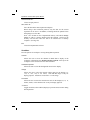
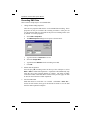
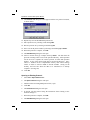
® MyoMonitor® Portable EMG System DelSys Inc. P.O. Box 15734 Boston, MA 02215 phone: (617) 236-0599 fax: (617) 236-0549 email: web: [email protected] www.delsys.com MyoMonitor® Portable EMG System User Manual February 2003 Edition Copyright © 2003, by Delsys Incorporated. Specifications and procedures outlined in this manual are subject to change without notice. ® ® Delsys Logo, EMGworks , and MyoMonitor are Registered Trademarks of Delsys Incorporated. MyoMonitor Portable EMG System Manual IMPORTANT INFORMATION Intended Use The MyoMonitor EMG Systems are designed for research, investigational and scholarship purposes only. DelSys products are not intended for measurement purposes or for use in the treatment and diagnosis of humans. Warnings and Precautions Delsys products are not designed to be used in conjunction with any devices not approved by Delsys Inc. Please contact Delsys for further information. Connecting a patient to high-frequency surgical equipment while using Delsys EMG systems may result in burns at the site of the EMG sensor contacts. Immediately discontinue device use if skin irritation or discomfort occurs. Immediately discontinue device use if a change in the device’s performance is noted. Contact Delsys technical support for assistance. Do not use Delsys products in the presence of any liquid or during conditions where the device or the user(s) may become exposed to liquids. The presence of liquids may compromise the safety features of the device. Delsys EMG amplifiers are extremely sensitive to electrical disturbances. Avoid static discharges and electromagnetic fields. Delsys Inc. guarantees the safety, reliability, and performance of the equipment only if assembly, modifications and repairs are carried out by authorized technicians; the electrical installation of the relevant room complies with the appropriate requirements; and the equipment is used in accordance with the instructions for use. © Delsys Incorporated 2 MyoMonitor Portable EMG System Manual Disclaimer DELSYS INC. makes no warranties, express or implied, as to the quality and performance of this product including but not limited to, any implied warranty of applicability for other than research uses by qualified individuals. DELSYS INC. shall not be liable to any person for any medical expenses or any direct or consequential damages resulting from any defect, failure or malfunction, whether a claim for such damages is based upon theory of warranty, contract, tort or otherwise. No representative, agent, or licensed practitioner is authorized to waive this disclaimer. DELSYS INC. makes no diagnosis or prescription by virtue of anything about this product. Limited Warranty The MyoMonitor® Portable EMG Systems are warranted against failure of materials and workmanship for a period of 180 days from the date of delivery, provided that the product is given proper care and has not been subject to abuse during this period. This warranty is in lieu of all other warranties expressed or implied. Operation of this device outside specified power supply or input voltage ranges specified by DELSYS INC. or use with any other input devices other than DELSYS INC. electrodes constitute an invalidation of this limited warranty. This warranty is not transferable. All devices to be returned require a return authorization number issued by DELSYS INC. All authorized returned merchandise must be shipped prepaid to DELSYS INC. If authorization for the return of a device is given, please insure the product in transit for any loss or damages that may occur. Technical Support Visit our web site at: http://www.delsys.com Tel: (617) 236-0599 © Delsys Incorporated 3 MyoMonitor Portable EMG System Manual Table of Contents MyoMonitor Portable EMG System .......................................................... 6 General Description ....................................................................... 6 Components................................................................................... 6 Getting Started with the MyoMonitor Portable EMG System.................... 7 Connect the HP Jornada to the Interface Unit ............................... 7 Turn on the HP Jornada Handheld ................................................ 8 Start the MyoMonitor Data Acquisition Hardware ......................... 8 Connect the Reference Electrode to the Interface Unit.................. 8 Connecting the Reference Electrode ............................................8 Attaching the Reference Electrode ........................................... 9 Connect the EMG Electrodes to the Interface Unit and Attach to Skin ............................................................................... 10 Connecting the EMG Electrodes............................................. 10 Orienting the Surface EMG Electrodes on the Skin................ 11 Using the DelSys Electrode Interface ..................................... 11 MyoMonitor Software.............................................................................. 13 Starting the MyoMonitor Data Acquisition Software ..................... 13 MyoMonitor Data Acquisition Workspace .................................... 13 File Menu ................................................................................ 13 View Menu .............................................................................. 14 Data Menu .............................................................................. 15 Recording EMG Data ................................................................... 16 Using Data Acquisition Protocols ................................................. 17 Creating a New Protocol ......................................................... 17 Opening an Existing Protocol.................................................. 18 Recording EMG Data with a Protocol ..................................... 19 Transferring Acquired EMG Data for Analysis ............................. 20 MyoMonitor Hardware ............................................................................ 21 DE-2.3 Single Differential Surface EMG Electrode ...................... 21 External Trigger............................................................................ 22 Troubleshooting...................................................................................... 23 Excessive Presence of Line Interference..................................... 23 Poor Electrode-Skin Adhesion ..................................................... 25 Excessive Presence of Motion Artifact......................................... 26 Restoring the MyoMonitor Software ............................................. 27 Restoring the Backup Folder on the CompactFlash Card............ 28 © Delsys Incorporated 4 MyoMonitor Portable EMG System Manual Specifications ......................................................................................... 29 MyoMonitor Portable EMG System ............................................. 29 Interface Unit ............................................................................... 29 DE-2.3 Electrode ......................................................................... 30 Reference Electrode Cable.......................................................... 30 Glossary of Commonly Used Terms ...................................................... 31 Table of Figures Figure 1: Connecting the A/D card and the Interface Unit ..................... 7 Figure 2: Connecting the Reference Electrode Cable............................ 8 Figure 3: Attaching the Reference Electrode ......................................... 9 Figure 4: Connecting the EMG Electrodes........................................... 10 Figure 5: Electrode orientation with respect to muscle fibers............... 11 Figure 6: Using the DelSys Electrode Interface ................................... 12 Figure 7: Removing the CompactFlash Memory Card ........................ 20 Figure 8: DE-2.3 Single Differential Surface EMG Electrode............... 21 Figure 9: Stereo plug schematic for trigger switch .............................. 22 Figure 10: Line Interference .................................................................. 23 © Delsys Incorporated 5 MyoMonitor Portable EMG System Manual ® MyoMonitor Portable EMG System General Description The MyoMonitor System is a portable electromyographic (EMG) data acquisition system. It is capable of recording up to 16 channels of EMG simultaneously and can display a specified channel in real time. The MyoMonitor EMG System is designed to make the acquisition of EMG signals hassle-free and reliable. The active electrodes are specifically designed to optimally detect EMG signals at the skin surface, while rejecting common noise signals such as motion and cable artifacts, yielding an excellent signal-to-noise ratio. In addition, the MyoMonitor EMG System’s portable design allows experiments to be conducted that would be impossible with conventional systems. Components The MyoMonitor Portable EMG System is comprised of the following items: • • • • • • • • • • • • • • 1 HP Jornada handheld computer with accessories 1 HP extended battery and charger 1 HP external charger 1 ComputerBoards PCM-DAS16/16 A/D card (installed) 1 128 megabyte CompactFlash memory card (installed) 1 SanDisk CompactFlash External Drive 4/8/16 DE-2.3 Surface EMG Electrodes 1 I/O Cable 1 Interface Unit (Channels 1-4 or 1-8) 1 Interface Unit (Channels 9-16)* 1 Interface Unit interconnect cable* 1 Carrying pouch 1 Trigger cable 1 EMG acquisition accessory set including reference electrodes and DelSys Electrode Interfaces * 16 Channel System only © Delsys Incorporated 6 MyoMonitor Portable EMG System Manual Getting Started with the MyoMonitor Portable EMG System The MyoMonitor Portable EMG System is shipped with the ComputerBoards PCM-DAS16/16 A/D card, CompactFlash memory card, and data acquisition software already installed. This section gives a description of the essential steps for start up and operation of the MyoMonitor Portable EMG System. Detailed information concerning the MyoMonitor software and hardware is provided in the latter sections of this manual. Detailed information concerning the operation of the HP Jornada handheld computer can be found in the HP Jornada User’s Guide provided with the system. Step 1: Connect the HP Jornada to the Interface Unit The I/O Cable bridges the ComputerBoards PCM-DAS16/16 A/D card in the HP Jornada handheld computer with the Interface Unit. Follow the instructions and figures below to make the connections. If using a 16 Channel MyoMonitor, the two Interface Units should also be connected together with the ribbon cable provided. Note: If the MyoMonitor Interface Unit is plugged into the A/D card after the Jornada is turned on, the A/D card and acquisition software can become temporarily disabled. To correct, close all programs and restart the Jornada. 1. With the Jornada turned off, connect the PCMCIA connector end of the cable into the A/D card. Make sure the white markings on the connector and A/D card line up . 2. Connect the SCSI connector end of the A/D cable into the I/O jack on the back of the MyoMonitor Interface unit. Figure 1: Connecting the A/D card in the Jornada and the Interface Unit. Follow the instructions above. © Delsys Incorporated 7 MyoMonitor Portable EMG System Manual Step 2: Turn on the HP Jornada Handheld Turn on the HP Jornada Handheld using the “on/off” button located on the top right of the keypad. Note: Allow several seconds for the Jornada to power up the A/D card before proceeding to initiate the software in Step 3. If the Jornada is not given sufficient time to power up the A/D card, an error message will appear, and the data acquisition software will not function. If this occurs all programs should be closed, and the Jornada should be restarted. Step 3: Start the MyoMonitor Data Acquisition Software Double click the MyoMonitor icon on the Windows CE desktop display or access it from the Start menu at the bottom of the screen, under Programs. The MyoMonitor software is described in detail beginning on page 13. Step 4: Connect the Reference Electrode Cable to the Interface Unit and attach to skin Connecting the Reference Electrode The MyoMonitor Portable EMG System is supplied with two different reference electrode cables. Both terminate in a “banana” style plug on one end. The “banana” plug is fitted in the receptacle labeled “REF” on the Interface Unit as shown in Figure 2. Only one reference connection is required, even if two Interface Units are being used, as with the 16 Channel MyoMonitor. Figure 2: Connecting the Reference Electrode Cable. The “banana” plug at the end of the reference electrode cable is inserted into the “REF” receptacle on the Interface Unit. © Delsys Incorporated 8 MyoMonitor Portable EMG System Manual Attaching the Reference Electrode Having a high quality electrical connection between the Reference Electrode and the skin is important in obtaining reliable EMG signals. The MyoMonitor Portable EMG System is supplied with two types of reference electrode cables. One terminates in an “alligator” clip and the other in a “tip” connector. The “alligator” clip is used to connect to the Red DotTM tab electrodes supplied in the accessory kit. The “tip” connector is used to connect to the Dermatrode® disk electrodes supplied in the accessory kit. The reference site, regardless of the type of reference electrode used, should be an electrically inactive area on the skin surface. As with the EMG electrode, conduction characteristics are optimized with proper skin preparation, which may include shaving excess hair and wiping the skin with isopropyl alcohol. Conductive electrodes other than the examples supplied can be used as substitutes. TM Red Dot electrode “alligator” clip a) “banana” connector electrically neutral skin surface b) “banana” connector ”tip” connector Dermatrode® electrode Figure 3: Attaching the Reference Electrode. The “alligator” clip (a) can attach to the tab on the Red DotTM electrode, while the “tip” connector (b) can attach to Dermatrode® disk electrode. © Delsys Incorporated 9 MyoMonitor Portable EMG System Manual Step 5: Connect the EMG Electrodes to the Interface Unit and Attach to Skin Connecting the EMG Electrodes The MyoMonitor Portable EMG System is supplied with DE-2.3 EMG Electrodes. These plug into the receptacles labeled CH 1, CH 2, etc., on the Interface Unit (Figure 4). To insert an electrode, align the button on the top of the electrode connector with the groove in the receptacle. To remove an electrode press the button on the top of the electrode connector and pull gently. The order of the electrodes can be interchanged with no consequences to the system’s performance. The electrode cables are five feet in length so that they can be placed on any part of a user’s body when the Interface Unit is mounted at waist level. Note: Electrodes plugged in when the Jornada is turned on may cause a power surge, and disable the A/D card and acquisition software. All programs should then be closed, the electrodes unplugged, and the Jornada restarted. Figure 4: Connecting the EMG Electrodes to the Interface Unit. The electrodes plug into the receptacles labeled CH 1, CH 2, etc., on the Interface Unit. ! CAUTION: Never use any electrode other than the DE-2.3 Surface EMG Electrode as an input to the MyoMonitor Portable EMG System. Connecting anything other than the specified electrode as an input to the MyoMonitor Portable EMG System constitutes an invalidation of the DelSys Warranty and may result in personal injury and/or permanent damage to the system or the electrodes. © Delsys Incorporated 10 MyoMonitor Portable EMG System Manual Orienting the Surface EMG Electrodes on the Skin Each DE-2.3 Surface EMG Electrode is fitted with two silver bar contacts for detecting the EMG signal at the skin surface. It is crucial that the orientation of these bars be perpendicular to the muscle fibers for maximum signal detection. The top of the electrode is stamped with an arrow to aid in the determination of this orientation. The arrow should be placed parallel to the muscle fibers underneath the electrode as demonstrated in Figure 5. At this point, the MyoMonitor software can be used as a scope to find the best position of the electrode on the skin to measure the EMG signal. The electrodes can then be easily attached to the skin with the DelSys Electrode Interface. Alternatively, surgical tape may be used. orientation arrow underlying muscle DELSYS direction of muscle fibers Figure 5: Electrode orientation with respect to muscle fibers. It is important that the orientation arrow on the electrode be parallel to the underlying muscle fibers. Using the DelSys Electrode Interface The DelSys Electrode Interfaces are made from medical grade adhesive specifically designed for dermatological applications. Usage of the interface promotes a high quality electrical connection between the electrode bars and the skin, minimizing motion artifacts and the ill-effect of line interference. To ensure a strong bond with the skin, it is advised to shave excessive hair and to wipe the skin area with isopropyl alcohol to remove oils and surface residues. Allow the skin to dry completely before applying the interfaces. Figure 6 illustrates the correct application of the Interface. © Delsys Incorporated 11 MyoMonitor Portable EMG System Manual 1) 3) 2) 4) muscle site (skin) Figure 6: Using the DelSys Electrode Interface. 1) Peel one interface from the paper backing to expose the first layer of adhesive. 2) Mount the interface on the electrode, taking care to align the electrode contacts through the interface slots. 3) Peel the white liner from the other side of the interface to expose the second layer of adhesive. 4) Attach the electrode to the desired muscle site on the skin surface. © Delsys Incorporated 12 MyoMonitor Portable EMG System Manual MyoMonitor Software The MyoMonitor software is used to control the data acquisition process. It allows the recording of up to 16 channels of EMG data and can display a selected channel in real time. In addition, the MyoMonitor software is equipped with the ability to establish signal acquisition protocols. Protocols permit the automatic acquisition of multiple data sets without user intervention. Starting the MyoMonitor Data Acquisition Software Double click the MyoMonitor icon on the Windows CE desktop display or access it from the Start menu at the bottom of the screen, under Programs. MyoMonitor Data Acquisition Workspace When the MyoMonitor software is opened, an new data acquisition workspace will automatically open, as shown below. File Menu Provides options for data acquisition and protocol management. New… Opens a new data acquisition workspace. If data was recorded in the previous workspace, the user will be prompted to save the data. The new workspace will inherit the properties of the previous workspace by default. Open Protocol File… Allows the user to open an existing EMG protocol file (*.epf) or to create a new protocol. See Page 14 on Using Data Acquisition Protocols. © Delsys Incorporated 13 MyoMonitor Portable EMG System Manual Close Protocol File… Closes an open protocol. Save, Save As… Saves the data in the data acquisition workspace. When using a data collection protocol, only the data for the current repetition can be saved. In addition, recording should be paused before attempting to save the data. Note: Save all data on the CompactFlash memory card called “Storage Saving on the memory card will also allow the data to be transferred to a desktop computer. (See Page 20) Card2” in order to conserve RAM on the HP Jornada. Exit Closes the MyoMonitor software. View Menu Provides options for workspace viewing during data acquisition. Channel Allows the user to select one channel of EMG data to display in the workspace. Alternatively the channel selection controls at the top of the workspace can be used to select the desired channel. Chart/Plot Properties Allows the user to select the background colors for the display. Voltage Allows the user to select the desired voltage range for the display (±5, ±2.5, ±1, ±0.5, ±0.2, or ±0.1 Volts). Note that this range is only for display purposes. All data is saved with a ±5 Volts range. Time Base Allows the user to select the desired time scale for the display (5s, 2s, 1s, 500ms, 250ms). Note that this scale is only for display purposes. √ Protocol Toggle menu that, when enabled, displays a protocol status window during data acquisition. © Delsys Incorporated 14 MyoMonitor Portable EMG System Manual Data Menu Provides control for data acquisition. Start Initiates the data acquisition. This function can be accessed directly from the play (X) recording control at the top of the workspace. Stop Pauses all data acquisition including protocols. This function can be accessed directly from the stop () recording control at the top of the workspace. Data acquisition can be resumed by selecting Data > Start or pressing the play (X) recording control. Rewind Erases all data in the workspace. In the case of an active protocol, only the current repetition will be erased. This function can be accessed directly from the rewind (WW) recording control at the top of the workspace. Data acquisition can be resumed by selecting Data > Start or pressing the play (X) recording control. Properties Opens the EMG Properties dialog box. This allows the user to specify the number of channels of EMG data to acquire and the duration of acquisition in seconds. Note that properties can only be changed before recording is initiated. √ External Trigger Synchronizes start of data acquisition with an external input. After selecting External Trigger, press play (X) or select Data > Start to begin data collection. The program will wait for the rising edge of a +5 volt signal on the trigger input to begin data acquisition. See the MyoMonitor Hardware section beginning on page 21 for more information on using the external trigger. Reset Re-initializes the ComputerBoards A/D card. © Delsys Incorporated 15 MyoMonitor Portable EMG System Manual Recording EMG Data There are three simple steps to record EMG data: 1. Change the Recording Properties There are two properties that must be set for an EMG data recording. These properties can only be set before the recording is initiated. If they are not set, the properties that were specified for the previous recording will be used by default. To set the properties: 2. a. Select Data > Properties. b. The EMG Properties dialog box will open, as shown below. c. Type the number of Channels to record. d. Select the Sample Rate. e. Type the desired Duration for the recording in seconds. f. Click OK. Initiate Data Acquisition Press the play (X) recording control at the top of the workspace or select Data > Start to initiate data acquisition. Acquisition will automatically stop when the end of the specified duration is reached. The other recording controls described in the Data Menu section on the previous page can also be used to control the flow of data acquisition. 3. Save the EMG Data EMG data must be saved after it is recorded. Select File > Save As…, choose the file location, and type in the desired file name to save the data from the data acquisition workspace. © Delsys Incorporated 16 MyoMonitor Portable EMG System Manual Using Data Acquisition Protocols EMG data can be recorded with the MyoMonitor Portable EMG System using structured data collection protocols. These protocols consists of a number of “protocol sets,” each consisting of a number of repetitions with the same duration and the same rest time. Creating a New Protocol 1. Select File > Open Protocol File… 2. The Open Protocol dialog box will open. 3. Select the desired folder to store the new protocol. 4. Type a unique protocol name in the Name field. 5. Click OK. 6. The Protocol File dialog box will open, as shown below. 7. Select the number of Channels to record and the Sample Rate. 8. Click Add to add a new protocol set. 9. The Add Protocol Item dialog box will open, as shown below. 10. Type a unique protocol Set name. 11. Type the duration for each repetition in the On field. 12. Type the duration for each rest period in the Off filed. 13. Type the number of repetitions in the Repeat field. 14. Click OK. © Delsys Incorporated 17 MyoMonitor Portable EMG System Manual 15. The Protocol File dialog box will reappear with the new protocol set listed, as shown below. 16. Repeat steps 8-14 to add additional protocol sets. 17. Edit a protocol set by selecting it and clicking Edit. 18. Delete a protocol set by selecting it and clicking Del. 19. Move a set in the protocol order by selecting it and clicking Up or Down. 20. When the protocol is complete, click OK. 21. The Data Directory dialog box will open. 22. Select a location and type a unique directory Name. The data from the protocol recording will be saved in the specified directory. Each repetition will be saved as a separate file with its protocol set name and repetition number. A copy of the protocol will also be saved in the directory. Note: Choose a location on the CompactFlash memory card called “Storage Card2” in order to conserve RAM on the HP Jornada. Saving on the memory card will also allow the data to be transferred to a desktop computer. (See Page 20) 23. Click OK. Opening an Existing Protocol 1. Select File > Open Protocol File... 2. The Open Protocol dialog box will open. 3. Find and select an existing EMG protocol file (*.epf). 4. Click OK. 5. The Protocol File dialog box will open. 6. If desired, edit the protocol using the instructions from Creating a New Protocol on Page 17. 7. When the protocol is complete, click OK. 8. The Data Directory dialog box will open. © Delsys Incorporated 18 MyoMonitor Portable EMG System Manual 9. Select a location and type a unique directory Name. The data from the protocol recording will be saved in this specified directory. Each repetition will be saved as a separate file with its protocol set name and repetition number. A copy of the protocol will also be saved in the directory. Note: Choose a location on the CompactFlash memory card called “Storage Card2” in order to conserve RAM on the HP Jornada. Saving on the memory card will also allow the data to be transferred to a desktop computer. (See Page 20) 10. Click OK. Recording EMG Data with a Protocol Once a data acquisition protocol has been created or opened, it is possible to begin collecting data. 1. Press the play (X) recording control at the top of the workspace or select Data > Start to initiate data acquisition. 2. If View > Protocol is checked, the protocol status window will be displayed in the lower right hand corner of the workspace and the current protocol set will be highlighted in blue, as shown below. In addition, the MyoMonitor Portable EMG System will provide audible cues to indicate the protocol status. It will produce a tone at the end of the recording of each repetition. It will also count down the last five seconds each rest period with ticks. 3. The recording controls described in the Data Menu section on Page 15 can be used to control the flow of data acquisition for each repetition of the protocol. 4. The repetitions will automatically be saved as they are completed. It is also possible to save the current repetition when recording is paused by selecting File > Save As… 5. Acquisition will be automatically stopped when the end of the protocol is reached. © Delsys Incorporated 19 MyoMonitor Portable EMG System Manual Transferring Acquired EMG Data for Analysis Once data collection with the MyoMonitor Portable EMG System is completed and all files are saved, follow the steps below to remove the CompactFlash memory card from the HP Jornada handheld computer. Please refer to the HP Jornada User’s Guide for more detailed instructions. 1. Open the CompactFlash memory card slot on the bottom of the computer. See the directions and figures shown on the bottom of the computer. 2. Gently pull the CompactFlash memory card out of the slot. Figure 8: Removing the CompactFlash Memory Card. Follow the instructions above. Use the SanDisk CompactFlash External Drive to transfer the EMG files from the CompactFlash memory card to the hard drive of a desktop computer. Please refer to the SanDisk documentation for instructions concerning the installation and use of the CompactFlash External Drive. With the EMG files on a desktop computer, they can be opened with EMGWorks software for analysis. © Delsys Incorporated 20 MyoMonitor Portable EMG System Manual MyoMonitor Hardware DE-2.3 Single Differential Surface EMG Electrode The differential electrode subtracts EMG potentials detected at two distinct locations on the surface of the skin, directly above an active muscle. The EMG potentials are always measured with respect to the electric potential of a neutral inactive site located away from the EMG muscle source. The electric potential of this neutral site is commonly termed the “reference” potential, and is accessed by the Reference Electrode. 10 mm Muscle site vout = v1-v2 10 mm v1 v2 1 mm Reference Figure 9: DE-2.3 Single Differential Surface EMG Electrode. The EMG signal is the result of the potential difference between v1 and v2 on the skin surface. The electrode housing is constructed with a waterproof polycarbonate plastic case, which is internally shielded to reject ambient electrical noise. The electrode contacts are made from 99.9% pure silver bars measuring 10 mm in length, 1 mm in diameter and spaced 10 mm apart for optimal frequency capture. These contacts detect the EMG potentials described above. The detected signals are subtracted and then amplified before being sent along a shielded cable to the rest of the EMG system. The 5-ft electrode cable terminates in a connector that hosts four contacts: two for power, one for the reference potential, and one for the electrode output. This connector mates with its socket located on the beltmounted Interface Unit. The following points should be kept in mind when handling the electrodes. • The electrodes can be cleaned and sterilized with a damp cloth and mild detergent or with isopropyl alcohol swabs. It is crucial that the electrode contacts remain clean at all times. • The electrodes are completely sealed and are water-resistant. These can be used on damp skin surfaces and in the presence of sweat without compromise to safety, electrode integrity, or operation. However, the electrodes should never be completely submerged in any liquid. © Delsys Incorporated 21 MyoMonitor Portable EMG System Manual • The electrode contacts are made of pure silver and are quite soft. Care should be taken to preserve the integrity of these contacts. Do not scrape or dent these contacts. Do not pull on the electrode cable. Avoid kinks in the cable, as these will result in damage to the internal cable wires and produce intermittent connections. Handle the electrode with care: do not drop them on the ground or step on them. • • ! CAUTION: The DE-2.3 Surface EMG Electrodes must only be used with the MyoMonitor Portable EMG System. The DE-2.3 electrodes are specifically designed for this system. Using these electrodes as inputs to any other device constitutes an invalidation of the DelSys Warranty and may result in personal injury and/or permanent damage to the electrodes or the system. ! CAUTION: The DE-2.3 Surface EMG Electrodes contain sensitive electronic circuitry. Static discharges and intense magnetic fields should be avoided to prevent possible irreparable damage to the electrodes. External Trigger The MyoMonitor Portable EMG System has a 2.5/3.5mm stereo jack for an external triggering device. A pushbutton trigger cable is provided with the MyoMonitor. The software triggers on the rising edge of a +5 volt signal (see software description on Page 15). The MyoMonitor was designed to provide it’s own +5 volt signal for the trigger. +5V +5V REF TRIG REF TRIG Figure 7: Stereo plug schematic for trigger switch. © Delsys Incorporated 22 MyoMonitor Portable EMG System Manual Troubleshooting Excessive Presence of Line Interference Power line interference from surrounding sources is always an issue to contend with when recording body potentials on the surface of the skin. This interference is due to the presence of a 60 Hz (or 50 Hz) displacement current flowing on the skin surface due to the capacitance between the body and ground and between the body and surrounding power sources (refer to Figure 10). People are exposed to this surface current on a continual basis, as it is present anytime a body is near an AC power source. This current cannot be sensed or felt, and poses no risk to the body it is flowing on. The surface potentials resulting from this displacement current on the skin can be orders of magnitude larger than the EMG potentials being detected by the electrodes. If the EMG system is working correctly, however, the detected amplitude of these interfering potentials are negligible when compared to the detected EMG potentials. Recall that the output of the EMG electrode is a subtraction of the potentials detected at the electrode contacts. The interfering potentials are large signals and change very little as they propagate across the space of the electrode contacts. The EMG potentials, on the contrary, change drastically as they propagate between the electrode bars. Ideally, the result is a differential EMG signal with a complete subtraction of the line interference (Figure 10 (b)). (a) EMG signal (b) muscle site differential electrode output power line voltage source displacement current capacitive coupling to ground v1+Vline v2+Vline vout = (v1+Vline)- (v2+Vline) = v1 – v2 line interference Figure 10: Line Interference. (a) The source of line interference in recorded EMG signals. Displacement current flows along the surface of the skin due to capacitive coupling between local AC voltage sources and ground. (b) The subtraction of power lineinduced voltages with a differential electrode. Line interference becomes overwhelmingly apparent if either of the following conditions arises: (a) the electrode does not subtract signals in an ideal fashion, (b) the quality of one or more electrode-skin contacts becomes compromised. The interference will appear as a high amplitude cyclic signal with a frequency of 60 Hz (for North American AC sources) or 50 Hz (for European, Australian and other foreign country AC sources). © Delsys Incorporated 23 MyoMonitor Portable EMG System Manual The first condition is intrinsic to the construction of the electrode preamplifier. The parameter used to gauge the electrode’s ability to subtract signals ideally is called the common-mode rejection ratio (CMRR) and is measured in decibels. Most surface bio-potential applications require a minimum CMRR of 80 dB. DelSys EMG electrodes have a typical CMRR of 92 dB, with a minimum at 84 dB. An electrode capable of subtracting signals perfectly would have an infinite CMRR. The second condition is within the user’s control, and is attributable to most instances of excessive line interference. It is crucial that the reference electrode and all the silver bars of the EMG electrodes make a high quality electrical connection with the surface of the skin. Failure to establish a high quality connection will drastically increase the probability of observing line interference. The following checklist should help in eliminating potential problem areas. 1. Turn “off” surrounding power sources. While it is generally not feasible to completely cut all the power in the ambient experimental area, all electronic equipment not in use should be turned off. The more AC power sources in the experimental area there are, the higher the probability of line interference. Pay careful attention to high current devices which radiate strong magnetic and electric fields such as motors, transformers, lights and equipment power supplies. If a portable computer is being used, it is advisable to disconnect the power supply (as these tend to be quite noisy) and run the machine from battery power for the data acquisition portion of the experiment. 2. Check electrode-skin contact. Ensure that all the electrodes are aggressively attached to the skin. The electrodes should not be easily dislodged when pulled by the connecting cables. Any portions of the electrode contacts not firmly pressed against the skin will result in line interference. The use of the DelSys Electrode Interfaces is recommended for this purpose. Refer to the section on “Poor Electrode-Skin Adhesion” if this is a problem. 3. Clean the skin. Ensure that the skin under all the electrodes is clean and free from hair. The area should be wiped with isopropyl alcohol swabs before the electrodes are applied. If necessary, hair can be removed with a safety razor or with commercially available hair removing lotions such as “Neet” or “Nair”. 4. Allow the electrode to settle. When first applied to the skin, the electrode may display high levels of noise and interference. Allow the electrode to settle for a few minutes, giving time for the ionic currents between the electrode and the skin to become established. Wetting the electrode bars with water will expedite this process. 5. Use surfactants. On particularly dry skin, it may be necessary to wet the EMG electrode contacts with water or to line them with electrode gel so as to promote the necessary ionic flow. For this purpose, it is recommended to use medical grade conductive gel, similar to those used for EKG and TENS applications. A very small amount should be applied to the electrode bars prior to attaching them to the skin. Cotton swabs can be used to spread a © Delsys Incorporated 24 MyoMonitor Portable EMG System Manual 6. 7. very thin layer on the silver bars. Take care not to smudge the gel on the skin when the electrodes are placed. Any connection between the electrode bars through the conductive gel will short circuit the input of the EMG electrodes and result in erroneous readings. Ionic soap is also an excellent surfactant of this purpose. As with the gels, it should be used in extremely small quantities. Check the Reference Electrode. It is crucial to have a well-established reference electrode contact. It may be necessary to use large EKG electrodes to ensure a high quality connection. Various samples of EKG electrodes are provided with the system. Test them to determine which is best for your application. Uncoil cables. Any cable carrying EMG signals (electrode cables, interface I/O cables, A/D cables) should be uncoiled and allowed to drape freely. Cables that are arranged in coils act like antennae, promoting the induction of line interference. Note that it is extremely difficult to eliminate all presence of line interference. In most situations a residual amount will always be present due to the finite electrode CMRR and the imperfect electrical connections between the skin and the electrode contacts. However, with proper use of the MyoMonitor-4 Portable EMG System, this residual amount should be insignificant and in most cases not detectable when compared to the amplitude of the EMG signal. Poor Electrode-Skin Adhesion For best results, it is recommended to use the DelSys Electrode Interfaces to attach the DE-2.3 EMG electrodes to the skin. Alternatively, surgical tape may be used. If the electrodes persistently fail to adhere to the skin, the following points should be addressed: 1. Clean and dry the skin. It is imperative that the skin be thoroughly cleaned before applying any type of adhesive. Allow the skin to completely dry after cleaning. Adhesive will not stick to wet or oily skin. Be sure to remove all hairs under the observation sites. This can be easily done with a safety razor or with commercially available hair removing lotions and waxes. 2. Remove dry skin cells. The human body is constantly generating skin tissue. New skin cells originate on the inner layer of the skin and grow outward towards the surface, progressing through several distinct layers and © Delsys Incorporated 25 MyoMonitor Portable EMG System Manual 3. 4. levels of activity. By the time the cells reach the skin surface, they become inactive on a cellular level and are generally considered to be dead. The body is constantly shedding this outermost cell layer, as it is replaced by the new cells from underneath. Since these inactive cells are easily dislodged from the skin, adhesives tend not to function properly when placed in contact with them. To avoid this problem, it is useful to remove the outermost layer of skin cells. This can be easily done by lining the skin with strips of surgical tape. When the tape is removed, most of these dry cells will be dislodged. This process can be repeated until satisfactory electrode adhesion is achieved. Check the shelf life of the interfaces or the tape. The DelSys Electrode Interfaces have an infinite shelf life if stored properly. The interfaces should be kept in airtight container to prevent the medical grade skin adhesive from drying and deteriorating. Keep in mind that other adhesives such as surgical tape have similar restrictions on their shelf life. Use elastic bandages. If difficulty in attaching the electrodes persists after addressing the above points, then one remaining alternative is to wrap the electrodes to the body with elastic bandages. Commercially available athletic wraps and bandages are suitable for this purpose if, obviously, the recording sites allow their use. Note that this method of electrode attachment is highly discouraged and should only be used as a last resort. Excessive Presence of Motion Artifact Motion Artifact is characterized by large amplitude, low frequency spikes which may saturate the sensitive EMG amplifiers. This type of electrical interference is usually associated with jarring motions, excessive stretching of the skin under the electrode sites and other forms of mechanical vibrations which cause movement of the electrode with respect to the skin. It is caused by a temporary fluctuation in the DC skin potential. While, the DelSys EMG systems and electrodes are specifically designed to be insensitive to fluctuations in DC skin potentials, complete immunity to motion artifact is impossible. The following points should be addressed when excessive motion artifact is present: 1. Strong electrode-skin adhesion. Ensure that the electrodes are robustly attached to the skin. It is crucial that there not be any electrode movement with respect to the skin at the recording site. DelSys Electrode Interfaces are specifically designed for this purpose. See the Troubleshooting section on “Poor Electrode-Skin Adhesion” if this is problem. 2. Provide sufficient cable slack. It is important that the electrode never be tugged by its cable. Some movements throughout an experiment may result in electrode cable tension. Take care to provide the necessary relief from cable-tension so that the electrode is not disturbed in any way. 3. Minimize jarring motions. Some types of activities (such as jogging) may © Delsys Incorporated 26 MyoMonitor Portable EMG System Manual cause vibration of the tissue located at the recording site. If possible, keep these activities to a minimum or modify them so as to reduce tissue vibration. Keep clothes clear. If electrodes are being used underneath loose clothing, ensure that body movements do not cause the clothes to disturb the electrodes or the skin in their vicinity. Note also that many fabrics can build high electrostatic charges, which may pose operational problems for the electrodes. Ensure high quality electrical contacts. In extreme cases it may be necessary to wet the electrode bars or use conductive gel to enhance the stability of the electrode-skin electrical connection. See the “Troubleshooting” section on “Excessive Presence of Line Interference” for methods to ensure a 4. 5. Restoring the MyoMonitor Software The program code for the MyoMonitor software resides in RAM (Random Access Memory). In order to maintain the integrity of this memory, a minimal amount of power is constantly needed. In the event that the main battery of the HP Jornada handheld computer is removed, an internal replaceable lithium cell provides power to maintain RAM integrity. If the main battery is not replaced in a relatively short period of time, this lithium cell will be drained. At this point, all programs and settings stored in RAM will be lost. It is first necessary to replace the lithium cell and restore function settings (refer the HP Jornada User’s Guide). Unlike RAM, CompactFlash memory maintains its integrity without power. A backup of the EmgCE program is installed on the CompactFlash memory card supplied. In order to restore the MyoMonitor program on the handheld computer: 1. Select Start > Programs > HP Applications > HP backup 2. Select Restore from the HP backup dialog box. 3. Select Restore all data from the HP backup: Restore dialog box. 4. An open dialog box will appear asking, “Where do you want to restore from?” Select “Storage Card2”, select the “Backup” folder, and select the “MyoMonitor backup.dba” file. This will reinstall the MyoMonitor software and all other settings that were originally shipped on the HP Jornada handheld computer. ! CAUTION: Do not erase the “Backup” folder from the CompactFlash memory card. This folder contains data necessary to restore the MyoMonitor system in case of battery power loss. © Delsys Incorporated 27 MyoMonitor Portable EMG System Manual Restoring the Backup Folder on the CompactFlash Card In the event that the backup information on the CompactFlash memory card becomes unusable, it can be restored from a copy located on the disk labeled “MyoMonitor Recovery Disk”. This procedure is performed from a desktop computer. 1. Insert the CompactFlash memory card into the CompactFlash External Drive. 2. Ensure that a directory labeled “Backup” exists on the CompactFlash memory card. If none exists, create one. 3. Insert the first MyoMonitor Recovery Disk into the CD-ROM of the desktop computer. 4. Copy the contents of the “Backup” directory on the Recovery Disk to the “Backup” directory on the CompactFlash memory card. Follow the associated prompts and instructions. Replace any old files that may be existing in the “Backup” directory. © Delsys Incorporated 28 MyoMonitor Portable EMG System Manual Specifications MyoMonitorTM Portable EMG System Number of Channels 4/8/16 analog EMG Amplification per Channel 1000 Channel Frequency Response 20±5 Hz to 450±50 Hz, 12 dB/octave Electrode CMRR 92 dB (typical) 84 dB (minimum) System Noise (R.T.I.) <1.2 µV(rms) for the specified bandwidth DC Offset <50 mV A/D card resolution 16 bits at ±5V (0.15mV) Power Requirements electrodes Jornada handheld ±4.5 to ±9 V @ 2mA refer to User’s Guide. Battery Life Up to 8 hours (1 Channel @ 1k sample rate) Mass 1.1 kg 2.5 lbs Interface Unit Number of Electrode Inputs 4/8 Electrode Input Connectors Hypertronics Output Connector 50 pin male SCSI board mount Case Dimensions 76 mm x 114 mm x 32 mm 3" x 4.5" x 1.25" © Delsys Incorporated 29 MyoMonitor Portable EMG System Manual DE-2.3 Electrodes Electrode Contacts 2 silver bars 10 mm x 1 mm diameter 0.394" x .039" diameter Contact Spacing 10 mm 0.394" Single differential configuration Electrode Dimensions 19.8 mm x 5.4 mm x 35 mm 0.78" x 0.21" x 1.38" Cable Length 1.67 m 5 ft. Connector Hypertronics Number of Conductors 4 (shielded) Case Material Polycarbonate plastic Reference Electrode Cable Connector “Banana” plug to “Alligator Clip” or “Tip” plug Conductor Single Length 1.67m 5 ft © Delsys Incorporated 30 MyoMonitor Portable EMG System Manual Glossary of Commonly Used Terms A/D Card: “Analog to Digital” Card. These devices are commonly used in conjunction with computers for translating continuous (i.e. analog) voltage signals into binary (i.e. digital) data. Once in digital format, the data can be viewed, manipulated and stored on the computer. Line Interference: The contamination of electrical signals by the superposition of cyclic noise induced by surrounding AC power lines and sources. In North America line interference has a fundamental frequency of 60 Hz, while in most European and other foreign countries the line interference has a fundamental frequency of 50 Hz. It is extremely difficult to completely remove the presence of line interference in noisy environments. In most cases, the optimum scenario is to keep line interference to unobservable low amplitudes when compared to the EMG signal amplitude. Motion Artifact: A transient disturbance in the detected EMG signal caused by the movement of the electrode with respect to the skin surface. Motion artifacts are undesirable and can be minimized by attaching the electrode to the skin with aggressive adhesive, by providing sufficient cable slack and by avoiding jarring motions and disturbances. Other types of transient disturbances include stimulus artifacts (caused by the applied voltage to a skin area for the purposes of eliciting a biological response) or electrostatic artifacts (caused by static discharges detected in the vicinity of the electrode). Reference Potential: An arbitrary voltage potential on the surface of the body used in establishing differential potential recordings. All voltages measured by the surface electrodes and propagated throughout the MyoMonitor-4 Portable EMG System have significance only when measured with respect to a welldefined Reference Potential. Note that the reference potential is not the same as, and is completely isolated from the Ground Potential. Sampling Frequency: This is an important parameter characterizing A/D systems. It is defined by the number of digital samples taken of an analog signal per second. According to the Nyquist criterion, it is crucial that the sampling frequency (expressed in Hertz) be at least twice the highest frequency component of the signal being sampled, in order to correctly capture all the information in the signal, and to avoid aliasing. The Bagnoli Systems have a maximum bandwidth of 15 Hz to 500 Hz. It is thus imperative that the sampling frequency be at least 1000 Hz. Signal-to-Noise Ratio: This is a mathematical technique used to express the energy of the EMG signal compared to the energy of the noise present. The SNR is defined as Vemg/Vnoise (expressed as a unitless number) or 20 log[Vemg/ Vnoise] (expressed in dB). Obviously, the higher the SNR, the better the quality of the recorded EMG signal. © Delsys Incorporated 31 MyoMonitor Portable EMG System Manual Surfactant: This class of substances are also called surface active agents or wetting agents, and are used to reduce the surface tension of some types of cleaning solutions. Their presence in certain types of soaps can be used to facilitate ion transfer across the skin to the EMG electrode contacts. © Delsys Incorporated 32