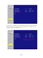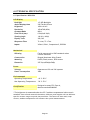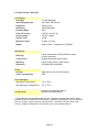
1
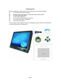
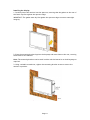
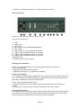
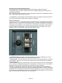
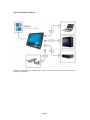
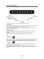
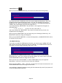
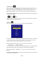
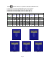
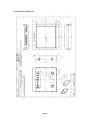
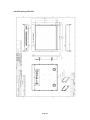
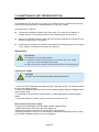
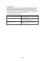
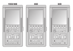
Navpixel™ USER MANUAL
NPD1236-12” IP-65 Marine Display
NDP1555- 15” IP-65 Marine Display
NPD1744- 17” IP-65 Marine Display
NPD1954- 19” IP-65 Marine Display
(1st Edition 3/31/2009)
All information is subject to change without notice.
Approved by
Checked by
Prepared by
Ming
Hank
Jack
Page 1
RECORD OF REVISION
Version and Date
Mar.31 2009
Page
Old Description
all
New Description
Preliminary Release
Page 2
Remark
TABLE OF CONTENT
RECORD OF REVISION ........................................................................................................ 2
TABLE OF CONTENT....................................................................................................... 3
1.0 INTRODUCTION............................................................................................................ 7
2.0 CONTROL AND FEATURES............................................................................................. 8
3.0 INSTALLATIONS ............................................................................................................ 9
4.0 TOUCH DRIVER INSTALLATIONS.................................................................................. 15
5.0 OSD OPERATIONS....................................................................................................... 39
6.0 TECHNICAL SPECIFICATION........................................................................................ 51
7.0 MAINTENAINCE AND TROUBLESHOOTING................................................................... 59
Page 3
IMPORTANT INFORMATION
EMC conformance
All Navpixel equipment and accessories are designed to the best industry standards for
use in the recreational marine environment. The design and manufacture of Navpixel
equipment and accessories conform to the appropriate ElectroMagnetic Compatibility
(EMC) standards, but correct installation is required to ensure that performance is not
compromised.
Waste Electrical and Electronic Equipment Directive
The Waste Electrical and Electronic Equipment (WEEE) Directive requires the recycling
of waste electrical and electronic equipment. Whilst the WEEE Directive does not apply
to some of Navpixel’s products, we support its policy and ask you to be aware of how to
dispose of this product.
The crossed out wheelie bin symbol, illustrated above, and found on our products
signifies that this product should not be disposed of in general waste or landfill. Please
contact your local dealer, national distributor or Navpixel Technical Services for
information on product disposal.
Restriction of the use of certain Hazardous Substances
This product uses components that comply with the requirements of the Restriction of
the use of certain Hazardous Substances (RoHS) Directive 2002/95/ EC.
Warranty
To register your new Navpixel product, please go to:
www.navpixel.com.
It is important that you complete the owner information to receive full warranty
benefits, including notification of software updates if they are required.
Page 4
Packing List
Before installation, please ensure the following items have been shipped:
z 1 x Navpixel Series Marine Display
z 4 x Mounting bracket lugs and 4 stainless steel threaded studs
z
1 x Power Cable (5000 mm)
z
1 x VGA Cable (3000 mm)
z
1 x CD for User Manual and Touch Driver
z
1 x Printed Flush Mount Template
z
1 x Printed User Manual
If any of these items should be missing or damaged, please contact your distributor
or sales representative immediately.
Page 5
Ordering Information
Model Number Description
NPD1236-EGAW-G01
12” Sunlight readable LCD, Optical bonding AR glass, 9~36V DC wide range input
power
NPD1236-ETAW-G01
12” Sunlight readable LCD, Optical bonding SR touch, 9~36V DC wide range input
power
NPD1555-EGAW-G01
15” Sunlight readable LCD, Optical bonding AR glass, 9~36V DC wide range input
power
NPD1555-ETAW-G01
15” Sunlight readable LCD, Optical bonding SR touch, 9~36V DC wide range input
power
NPD1744-EGAW-H01
17” Sunlight readable LCD, Optical bonding AR glass, 9~36V DC wide range input
power
NPD1744-ETAW-H01
17” Sunlight readable LCD, Optical bonding SR touch, 9~36V DC wide range input
power
NPD1954-EGAW-H01
19” Sunlight readable LCD, Optical bonding AR glass, 9~36V DC wide range input
power
NPD1954-ETAW-H01
19” Sunlight readable LCD, Optical bonding SR touch, 9~36V DC wide range input
power
Optional Accessories
810130001000 VGA Cable 3000mm. D-SUB15P TO D-SUB 15P
810650005110 Power Cable, DC, 5000mm, TERMINAL TO OPEN, 14AWG*2C
Page 6
1.0 INTRODUCTION
About Navpixel™ Marine Display
Navpixel™ Series Marine Display, the high-performance, equipped with optical bonding
AR glass or sunlight readable touch monitor, is specially engineered to survive the most
demanding applications. You will soon become familiar with the quality difference in
this bright sunlight readable (0.5 to 1,000 nits) monitor.
The range of Navpixel Sunlight Viewable Marine Displays has been developed to be used
as part of an integrated marine navigation system or within an entertainment system.
The displays, available in several sizes, are designed to be waterproof and suitable for
use above or below decks.
The Navpixel™ Series Marine Display sunlight readable monitor handles a wide-range of
extreme environments making it the industry choice for mobile applications. Housed in a
milled billet aluminum case, the slim-profile Navpixel™ Series Marine Display is light
weight and watertight. Front-mounted controls and the touch screen make the industrial
rugged monitor user-friendly. We have incorporated the latest optical engineering to
achieve optimal viewability in all lighting conditions, including direct sunlight. The
Navpixel™ Series Marine Display’s power efficient, low heat design results in increased
reliability and longevity required for mission critical deployment.
This handbook contains important information on the installation, operation and
maintenance of the Navpixel Sunlight Viewable Marine Display range which is intended
for use in the recreational marine market and covers all models.
Page 7
2.0 CONTROL AND FEATURES
Your Navpixel Sunlight Viewable Marine Display has the following controls and features:
Front View
Remarks: The PIP function is only available for NPD1744 and NPD1954 model
Back View
Remarks: Only DVIx1 and VGAx1 for NPD1236 and NPD1555 model
Page 8
3.0 INSTALLATIONS
It is important that your new display is installed and operated in accordance with the
instructions provided in this handbook. Failure to do so could result in poor product
performance and may invalidate your warranty.
When planning the installation the following points must be considered:
• Your Navpixel display is sunlight viewable and visible in direct sunlight..
• If temperatures exceed the normal temperature operating range the display could
overheat and begin to blackout due to the limitations of TFT LCD technology.
• In order to minimize the chances of a malfunction, the following precautions should be
taken during installation:
• The display should be installed in an area where there is proper and adequate
ventilation (min. 15cm clearance) . If it is possible to cool the area behind the
display, it will significantly reduce the risk of a malfunction.
• The display should be mounted at an angle to the sun. We do not recommend
mounting the unit in a flat plane, which increases the surface area exposed to the
sun and leads to increased heat absorption.
IMPORTANT: Your Navpixel display is only waterproof from the front. To maintain
watertight integrity the display must be flush mounted ensuring that the rear casing is
enclosed in a watertight enclosure.
The Navpixel™ Series Marine Display is designed to be mounted in two configurations:
VESA75 / VESA100 MOUNT
The Navpixel™ Series Marine Display is designed compatible with VESA75 and VESA100
mount. By installing the monitor with this kit, the user can adjust the viewing angle to
improve viewability in changing environments. This mounting system has proven to be
successful in supporting an extreme amount of weight in high vibration and
difficult-mount applications.
Page 9
The back of the monitor includes mounting points that you can use to mount the monitor
as your installation requires.
Mounting holes on the Navpixel™ Series Marine Display allow the monitor to be mounted
by rear mounted using VESA75 or VESA100 mount
PANEL (Flush) MOUNT
For installation, there are four tapped mounting holes on the two sides of the unit’s
panel. The mounting hardware packet is included with the product accessories in the
shipping box. This packet includes four (4) stainless steel threaded studs, 3.2 cm and
four (4) mounting lock nuts.
Your monitor can be installed using the mounting lock nuts (supplied) in the vertical
keyways. Make sure that both brackets are in the same orientation.
Preparing the installation site
1. Select an installation site that has sufficient space behind for cable connections and
ventilation.
2. Tape the supplied flush mount template in the required position.
3. Using a jigsaw, carefully remove the shaded portion of the template.
4. Using a suitable file, smooth the edges of the aperture.
Page 10
Installing the display
1. Carefully insert the monitor into the aperture, ensuring that the gasket on the rear of
the fascia lays flat against the aperture edge.
IMPORTANT: The gasket must lay flat against the aperture edge to ensure watertight
integrity.
2. Place the mounting bracket lugs into the keyways and move them to the rear, securing
the bracket to the monitor.
Note: The mounting brackets can be used in either the horizontal or vertical keyways as
required.
3. Using a suitable screwdriver, tighten the mounting bracket screws to secure the
monitor in position.
Page 11
4. Connect all cables as required - see “Rear connections” below.
Rear connections
Remarks: The photo above will differ for different model
The rear connectors are:
1. FUSE
2. Power Input
3. DVI-1 Input
4. DVI-2 Input (N/A for NPD1236 & NPD1555)
5. VGA-1 Input
6. VGA-2 Input (N/A for NPD1236 & NPD1555)
7. CVBS-1 Input (Composite Video) for AV input
8. CVBS-2 Input (Composite Video) for AV input
9. CVBS-3 Input (Composite Video) for AV input
10. RS232 Input
11. USB for Touch control (option)
Planning the installation
Before you install your display, the following points should be considered:
• Power requirements.
• Display location and mounting options.
• Additional accessories, e.g. keyboard or speakers.
Power requirements
Your Sunlight Viewable display is designed to run on boat’s DC power systems rated at 12
V or 24 V. Navpixel Series Marine Display is equipped with 9~36V DC wide range power
input and is capable for such kind of application.
The DC power system should be either:
• Negative grounded, with the negative battery terminal connected to the boat’s
ground,
• Floating, with neither battery terminal connected to the boat’s ground.
Grounding the display
It is important that an effective radio frequency (RF) ground is connected to the display.
You must ground the display by connecting the drain wire (shield) of the power input
cable to the nearest ground point of the boat’s RF ground system.
Page 12
Display location and mounting options
Your display can be mounted using the flush mounting kit supplied. Navpixel
recommends that you power the unit and select a suitable mounting location prior to
installing the display.
When planning the display location, the following points should be considered to ensure
safe, comfortable and reliable operation:
• Convenience- the mounting location should be easily accessible to allow operation of
the controls and should enable easy viewing of the display.
Power connections
The power connection to the display should be made at either the output of the battery
isolator switch, or at a DC power distribution panel. Navpixel recommends that power is
fed directly to the display via its own dedicated cable system and MUST be protected by
a thermal circuit breaker or fuse, fitted close to the power connection. If you do not
have a thermal circuit breaker or fuse in your power circuit, you MUST fit an in-line
breaker or fuse to the positive (red) lead of the power cable.
• Installation angle- the display should be mounted at an angle. Mounting it in a flat
plane is not recommended due to increased heat absorption.
• Viewing angle - this LCD has been chosen to give the very best performance, including
viewing angle. However, the contrast and colors seen on all LCD displays vary slightly
with viewing angle.
• Environment - to prevent overheating, do not restrict airflow at the rear of the display
unit; If the space behind the display is air conditioned or cooled by a fan, it will help in
keeping the unit’s temperature down when mounted in direct sunlight.
FAILURE TO ADEQUATELY VENTILATE THE UNIT COULD INVALIDATE YOUR WARRANTY.
The display should be protected from physical damage and excessive vibration. Although
the display unit is waterproof from the front when installed correctly, it is good practice
to mount it in a protected area away from prolonged and direct exposure to rain and salt
spray. DO NOT place the display near to a heat source.
Page 13
Typical Installation Diagram
Remarks: The real installation diagram above is only for reference and will differ for different kind of
customer’s applications
Page 14
4.0 TOUCH DRIVER INSTALLATIONS
Both AR glass and Resistive touch screen solutions are used for our products. If you
have a customized or tailored product, please check the specifications in this
manual or provide us your third-party specifications.
Resistive Touch Screen
It generally uses a display overlay composed of layers, each with a conductive
coating on the interior surface. Special separator “dots” are distributed evenly
across the active area and separate the conductive interior layers. The pressure
from using either a mechanical stylus or finger produces an internal electrical
contact at the “action point” which supplies the controller with vertical and
horizontal analog voltages for data input. The resistive touch screens are anti-glare
to reduce reflective shine intensity, which will slightly diffuse the light output
throughout the screen. Resistive technology activation can be initiated by; a gloved
hand, fingernail, mechanical stylus or an ungloved finger.
Resistive Touch - Brief Specifications
Subject
Input Method
Touch Activation Force
Insulation Resistance
Light Transmission
Operating Temperature
Storage Temperature
Humidity (Operating)
Surface Hardness
Expected Life
Details
Finger & Stylus Finger & Stylus
Touch Stylus Touch Stylus
Gloved Hand
0.10 - 0.80N (10 - 80g)
10M ohm @ 25V DC
> 80%
-10℃ to +60℃
-40℃ to +80℃
less than 80% RH
3H or higher
10 million single point activation
Before installing the Windows 2000、XP32/64bit、2003、Vista32/64bit driver software,
you must have the Windows 2000、XP32/64bit、2003、Vista32/64bit system installed
and running on your computer. You must also have one of the following PenMount
5000/6000/9000 series controller or control boards installed:
PM5184 , PM5126 , PM51A5,
PM6500 , PM6300, PM6200C,
PM9084 , PM9026 , PM9036 , PM90A4.
Installing Software
If you have an older version of the PenMount Windows 2000、XP32/64bit、2003、
Vista32/64bit driver installed in your system, please remove it first. Follow the steps
below to install the PenMount Windows Universal driver.
1. Please make sure your PenMount device had plugged in advance. If your device
uses RS-232 interface, please plugged in before the machine is turned on. When the
system first detects the controller board, a screen appears that shows "Unknown
Device". Do not use this hardware wizard. Press Cancel.
2. Insert the PenMount Driver CD-ROM. Go to the Windows Universal Driver folder.
Page 15
Click “setup.exe.”
3. A License Agreement appears. Click “I Agree” and “Next”
Page 16
4. Ready to Install the Program. Click “Install”
5. Installing may be will spend sometime.
Page 17
6. When the warning message screen appears, please click “Install this driver
software anyway” to continue.
For RS232 interface, it will appear one time.
For USB interface, it will appear twice.
7. The “InstallShield Wizard Completed” appears. Click “Finish”.
If you are installing the driver with Microsoft WHQL, you will see the screen in step 7
directly instead of step 6.
Please restart your Windows system after installation finishes.
Page 18
8. If you installed PenMount driver package 2.1.0.187 and after, you can use the
“Refresh” function in PenMount Control Panel to detect and install newly attached
PenMount devices.
Software Functions
Upon rebooting, the computer automatically finds the new PenMount controller
board. The touch screen is connected but not calibrated. Follow the procedures
below to carry out calibration.
1. After installation, click the PenMount Monitor icon “PM” in the menu bar.
2. When the PenMount Control Panel appears, select a device to “Calibrate.”
PenMount Control Panel
The functions of the PenMount Control Panel are Device, Calibrate, Setting,
Multiple Monitors ,Tools and About, which are explained in the following sections.
Page 19
Device
In this window, you can find out that how many devices be detected on your
system.
Page 20
Calibrate
This function offers two ways to calibrate your touch screen. ‘Standard Calibration’
adjusts most touch screens. ‘Advanced Calibration’ adjusts aging touch screens.
Page 21
1. Please select a device then click “Configure”. You can also double click the device
too.
2. Click “Standard Calibration” to start calibration procedure
Page 22
NOTE: The older the touch screen, the more Advanced Mode calibration points you
need for an accurate calibration. Use a stylus during Advanced Calibration for
greater accuracy. Please follow the step as below:
3. Come back to “PenMount Control Panel” and select “Tools” then Click “Advanced
Calibration”.
Page 23
Select “Device” to calibrate, then you can start to do “Advanced Calibration”.
NOTE: Recommend to use a stylus during Advanced Calibration for greater accuracy.
Page 24
Setting
Page 25
Edge Compensation
This page is the edge compensation settings for the advanced calibration. You can
adjust the settings from 0 to 30 for accommodating the difference of each touch
panel.
Page 26
About
This panel displays information about the PenMount controller and driver version
Multiple Monitors
Multiple Monitors supports from two to six touch screen displays for one system.
The PenMount drivers for Windows 2000、XP32/64bit、2003、Vista32/64bit support
Multiple Monitors. This function supports from two to six touch screen displays for
one system. Each monitor requires its own PenMount touch screen control board,
either installed inside the display or in a central unit. The PenMount control boards
must be connected to the computer COM ports via the RS-232 interface. Driver
installation procedures are the same as for a single monitor. Multiple Monitors
supports the following modes:
Windows Extend Monitor Function
Matrox DualHead Multi-Screen Function
nVidia nView Function
NOTE: The Multiple Monitors function is for use with multiple displays only. Do not
use this function if you have only one touch screen display. Please note once you
turn on this function the Rotating function is disabled.
Enable the multiple display function as follows:
Page 27
1. Check the “Multiple Monitor Support” box; then click “Map Touch Screens” to
assign touch controllers to displays.
2. When the mapping screen message appears, click “OK”
Page 28
3. Touch each screen as it displays “Please touch this monitor. Press ‘S’ to skip”
Following this sequence and touching each screen is called mapping the touch
screens.
4. After the setting procedure is finished, maybe you need to calibrate for each
panel and controller
NOTES:
1. If you used a single VGA output for multiple monitors, please do not use the
Multiple Monitors function. Just follow the regular procedure for calibration on
each of your desktop monitors.
2. The Rotating function is disabled if you use the Multiple Monitors function.
3. If you change the resolution of display or screen address, you have to redo Map
Touch Screens so the system understands where the displays are.
4. If you more monitor mapping one touch screen, Please press ‘S’ to skip mapping
step.
Page 29
An example for 2 units of touch monitor
a. Please make sure the touch monitor had plugged in and detected.
Page 30
b. click “Map Touch Screens” then click “OK"
c. Please follow the message show the display to match the controller and touch
screen
c-1. Please click “S” to skip if the monitor without use touch screen.
Page 31
c-2. When screen jump to Screen 2, please touch it. If screen 2 has no touch function,
press “S” to skip it.
d. Before doing the calibration, you have to finish the procedure of “Map touch
screens”
d-1. Please do the calibration for each device in sequence.
Page 32
d-2. Press each device & start to do standard Calibration, for instance, device 0.
d-3. After press device 0, one of screens will show calibration map. Please follow
points to calibrate it. When you completed one device, do please do others as the
same way.
Page 33
Tools
Page 34
About
You can see how many devices of PenMount controller that are plugged to your
system
PenMount Monitor Menu Icon
The PenMount monitor icon (PM) appears in the menu bar of Windows
2000/XP/2003/Vista system when you turn on PenMount Monitor in PenMount
Utilities.
Page 35
PenMount Monitor has the following function
PenMount Rotating Functions
The PenMount driver for Windows 2000/XP 32 bit/Vista 32/64bit supports several
display rotating software packages. Auto detect rotate function (0°, 90°, 180°,
270°).
Windows 2000/XP 32 bit/Vista 32/64bit support display rotating software packages
such as:
• Portrait’s Pivot Screen Rotation Software
• ATI Display Driver Rotate Function
• nVidia Display Driver Rotate Function
• SMI Display Driver Rotate Function
• Intel Display Driver Rotate Function
Page 36
Configuring the Rotate Function on Windows XP 64 bit
1. There is a “screen rotation monitor” function only appears in the PenMount driver
utilities for Windows XP 64 bit Edition.
2. On enabling the ”Screen Rotation Monitor”, you can see a screen like below :
3. Choose the rotate function (0°, 90°, 180°, 270°) in the 3rd party software. The
calibration screen appears automatically. Touch this point and rotation is mapped.
NOTE: The Rotate function is disabled if you use Monitor Mapping
Page 37
Uninstall Software
1. Exit the PenMount monitor (PM) in the menu bar in advance.
2. Go to Settings, then Control Panel, and then click “Add/Remove program”
3. Select ”PenMount Universal Driver 1.0”. Click the “Chang/Remove” button.
4. Select ‘Yes’ to remove the PenMount driver.
5. Select ‘Yes’ to reboot your system or ‘No’ to reboot your system later.
Page 38
5.0 OSD OPERATIONS
(Remarks: PIP function is only available for NPD1744 and NPD1954 model)
Introduction
Your Navpixel Sunlight Viewable display can be controlled using the On Screen Display
(OSD) menu and/or the 8 buttons on the front bezel of the unit.
The OSD menu enables you to change the way in which your display is set up and is
accessed using the Menu button.
Using the buttons
Each of the 8 buttons on the front bezel of your display has an input and a control
function.
Input functions enable you to select the type of signal input to the display.
Control functions enable you to change the appearance of the display.
Power
Power ON Key
To power your monitor ON, just need to press this button and it will delay the power on
sequence around 3 seconds. This is Navpixel’s brand new design to well protect your
Navpixel Sunlight Viewable display damaged in the surge voltage from the engine.
Power OFF Key
To power your monitor OFF, just need to press this button and it will also delay the
power off sequence around 3 seconds.
Pressing the power button will display a list of what input for the main screen is
associated with each button. This is just a reminder and is not part of the input selection
process.
Page 39
BRIGHTNESS Key
When you press the BRIGHTNESS Key, the screen will show the following image
You can press the UP /DOWN Key to do the screen brightness adjustment. When the
brightness achieve 50 and keeping pressing “UP” Key, the dimming will keep the
brightness at 50. When you dimming down to brightness 1 and keeping pressing the
“DOWN” Key, the dimming will keep the brightness at 1.
If you keep pressing “BRIGHTNESS” Key and hold it, the brightness will appear as
following status:
. . . .2 Æ 1 → 2→ 3 → . . . Æ 48 Æ 49 Æ 50 Æ 49 Æ 48 Æ . . . .
And if you release the “BRIGHTNESS” Key around 5 seconds with any action, the
brightness bar will disappear.
When you press “BRIGHTNESS” Key and other Key (not including Up/Down Key), the
BRIGHTNESS status bar image will disappear.
When you press NIGHT MODE KEY or choose VR adjustment, the BRIGHTNESS KEY will be
no function if you press it.
VR BRIGHTNESS Key
If you want to enable the VR Brightness function, you need to press “MENU” KEY and
then choose VR function. When you rotate the VR knob, the VR BRIGHTNESS status bar
will appear as below image (dimming range from 1~50):
When you enter the VR BRIGHTNESS mode, it will be no function if you press the
BRIGHTNESS KEY. And if you release the VR knob without any action around 5 seconds,
the VR BRIGHTNESS Status bar image will be closed.
When you enter the “NIGHT MODE” or choose “BRIGHTNESS” Key for brightness
adjustment, it will be no function if you control the VR knob.
When you press “MENU”, “DISP”, “PIP” Key, you will enter the menu item selection. And
the VR BRIGHTNESS status bar image will be closed.
Any modified or changed parameter setting will be automatically saved if you power off
or Exit the BRIGHTNESS status bar.
Page 40
NIGHT MODE KEY
When you press the “NIGHT MODE” KEY, the dimming will be down to under 0.5 nit
directly. And if you press “BRIGHTNESS” KEY or “VR” knob at this moment, it will be no
function until you press the “NIGHT MODE” KEY again to release this restriction.
When you press “MENU”, “DISP”, “PIP” Key, you will enter the menu item selection.
Any modified or changed parameter setting will be automatically saved if you power off
or Exit the NIGHT MODE.
UP
/ DOWN
KEY
It works as menu item selection use, the “UP”KEY can be used as “RIGHT” KEY and the
“DOWN” KEY can be used as “LEFT”KEY.
INPUT KEY
When you press “INPUT” KEY, the screen will pop up the following image:
You can press the “UP”/ ”DOWN” KEY for the menu item selection above. It will remain
at “VIDEO 3” position if you keep pressing “DOWN” KEY to the end. And it will also
remain at “RGB1” position if you keep pressing “UP” KEY to the end.
When you press and hold the “INPUT” KEY, the menu screen will show as
RGB1→RGB2→..→VIDEO3→VIDEO2→..
If you release the “INPUT” KEY for 5 seconds without any action, the menu selection
screen will be closed. And it will remain at the item which you’d selected.
When you press “MENU”, “BRIGHTNESS”, “PIP” Key, you will enter the menu item
selection.
Any modified or changed parameter setting will be automatically saved if you power off
or Exit the menu setting screen.
Page 41
PIP KEY
1.
2.
3.
4.
5.
Default
Default
Default
Default
Default
(Remarks: PIP KEY is no available for NPD1236 and NPD1555 model)
main
main
main
main
main
screen
screen
screen
screen
screen
shows at RGB1 & RGB2Æ Press “PIP” KEYÆ Figure 1
stays at DVI1 & DVI2Æ Press “PIP” KEYÆ Figure 2
stays at VIDEO 1Æ Press “PIP” KEYÆ Figure 3_1
stays at VIDEO 2Æ Press “PIP” KEYÆ Figure 3_2
stays at VIDEO 3Æ Press “PIP” KEYÆ Figure 3_3
PIP Function Supporting Table Sub RGB 1 Main RGB 1 RGB 2 DVI 1 OK DVI 2 OK VIDEO 1 OK VIDEO 2 OK VIDEO 3 RGB 2
DVI 1
DVI 2
VIDEO 1
VIDEO 2 VIDEO 3
OK OK OK OK OK OK OK OK OK OK OK OK OK OK OK OK OK OK OK OK OK OK OK OK OK OK OK OK OK OK OK OK OK Figure 1 OK Figure 1 Figure 1 Figure 2 Figure 2 Figure 3_1 Figure 3_2 Figure 3_3 Figure 2 Figure 3_1 Figure 3_2
Page 42
Figure 3_3
When you enter the “PIP Port Change” screen, the status bar will remain at “OFF”
position if you keep pressing the “DOWN” KEY to the end. At the other hand, the
status bar will remain at top item of each menu if you keep pressing the “UP” KEY to
the end.
When you press and hold the “PIP” KEY, the menu screen will show as:
DVI→VIDEO1→VIDEO2→VIDEO3→OFF→VIDEO3→VIDEO2→VIDEO1→DVIÆVIDEO1Æ…
If you release the “INPUT” KEY for 5 seconds without any action, the menu selection
screen will be closed. And it will remain at the item which you’d selected.
When you press “MENU”, “BRIGHTNESS”, “PIP” Key, you will enter the menu item
selection.
Any modified or changed parameter setting will be automatically saved if you power off
or Exit the menu setting screen.
MENU KEY
When you press “MENU” KEY, the Navpixel OSD main menu screen will appear as below:
If you release the “MENU” KEY for 30 seconds without any action, the menu OSD screen
will disappear automatically. You can also choose “QUIT” and then press “MENU” KEY to
exit this OSD menu screen.
Page 43
RGB1 & 2’s setting screen: (Remarks: Only RGBx1 for NPD1236 and NPD1555 model)
RGB Setting Item Description:
・ PHASE――― Horizontal Sampling Phase Adjustment。
・ CONTRAST――― Contrast Adjustment。
・ H_POSITION―― Horizontal Screen Adjustment。
・ V_POSITION―― Vertical Screen Adjustment。
・ R_LEVEL――― Red Color level Adjustment。
・ G_LEVEL――― Green Color level Adjustment。
・ B_LEVEL――― Blue Color level Adjustment。
・ TEMPERATURE――― Color Temperature Adjustment。
・ DISP MODE―――
FULL――― Full Screen。
EVEN――― Half Screen。
NORMAL―― Keep normal aspect ratio。
・ AUTO ADJUST――― Auto adjustment。
・ EXIT――― Quit from current setting。
・
(Remarks: DISP MODE is not available for NPD1236 and NPD1555 model)
Page 44
DVI 1 & 2’s setting screen: (Remarks: Only DVIx1 for NPD1236 and NPD1555 model) DVI Setting Item Description:
・ CONTRAST―――Contrast Adjustment。
・ R_LEVEL――― Red Color level Adjustment。
・ G_LEVEL――― Green Color level Adjustment。
・ B_LEVEL――― Blue Color level Adjustment。
・ TEMPERATURE――― Color Temperature Adjustment。
・ DISP MODE―――
FULL――― Full Screen。
EVEN――― Half Screen。
NORMAL―― Keep normal aspect ratio。
・ EXIT――― Quit from current setting。
(Remarks: DISP MODE is not available for NPD1236 and NPD1555 model)
Page 45
VIDEO 1 & 2 & 3’ setting screen:
VIDEO Setting Item Description:
・ CONTRAST――― Contrast Adjustment。
・ SHARPNESS――― Horizontal edge sharpness
・ HUE――― Color Adjustment
・ R_LEVEL――― Red Color level Adjustment。
・ G_LEVEL――― Green Color level Adjustment。
・ B_LEVEL――― Blue Color level Adjustment。
・ TEMPERATURE――― Color Temperature Adjustment。
・ EXIT――― Quit from current setting。
(Remarks: HUE function is not available for NPD1236 and NPD1555 model)
Page 46
PIP Sub-menu setting screen: (Remarks: PIP function is not available for NPD1236 and
NPD1555 model)
PIP Setting Item Description:
・ PIP_SIZE――― Picture in Picture Screen Size Adjustment。
・ CONTRAST――― Contrast Adjustment。
・ R_LEVEL――― Red Color level Adjustment。
・ G_LEVEL――― Green Color level Adjustment。
・ B_LEVEL――― Blue Color level Adjustment。
・ EXIT――― Quit from current setting。
Page 47
OSD setting screen:
OSD Setting Item Description:
・ H_POSITION―― Horizontal Screen Adjustment。
・ V_POSITION―― Vertical Screen Adjustment。
・ TRANSLUCENT――― Screen background color can be adjusted as transparent
as you want (total 10 scales)。
・ BRIGHTNESS――― Selection between “BRIGHTNESS” key or “VR” Button for
brightness adjustment。
・ SYSTEM RETURN――― Restore all parameter setting to factory default value。
・ EXIT――― Quit from current setting。
(Remarks: TRANSLUCENT function is not available for NPD1236 and NPD1555
model )
SYSTEM RETURN setting screen:
Page 48
You may choose “SYSTEM RETURN” selection item on the OSD Screen to restore all of the
parameter setting to factory default value. When you press “UP” or “RIGHT” KEY, the
parameter will show “YES” and confirm it.
Page 49
“KEY LOCK” Mode Function setting screen:
When you press “MENU” and “BRIGHTNESS” KEY simultaneously for 3 seconds, you will
enter the “KEY LOCK” mode. At the same time, the screen will show “KEY LOCK” image
as below for 5 seconds and then disappear.
In the “KEY LOCK” mode, it will be no function to press any key. When you press the key
in the “KEY LOCK” mode, the screen will show “KEY LOCK” image as below for 5 seconds
and then disappear.
To Release/Unlock “KEY LOCK” Mode Function setting screen:
In the “KEY LOCK” mode, when you press “MENU” and “BRIGHTNESS” KEY simultaneously
for 3 seconds, you will release/unlock the “KEY LOCK” mode. At the same time, your
screen will show “KEY UNLOCK” image as below.
Page 50
6.0 TECHNICAL SPECIFICATION
6.1 Specification- NPD1236
LCD Display
Backlight
12" LED Backlight
Active Display Area
Brightness
245.76x184.32 mm
1000 cd/m2 *
Resolution
1024x768 (XGA)
Contrast Ratio
Pixel Pitch (mm)
800:1
0.24(H)x0.24(V)
Viewing Angle
140 (H), 140(V)
Display Color
262,144
Response Time
Tr: 6ms, Tf: 17ms
Inputs
VGAx1, DVIx1, Composite x3, RS232x1
Mechanical
IP Rating
Facial waterproof to IP65 standards when
console mounted.
Construction
Rugged Aluminum Alloy Chassis
Mounting
Panel (Flush) mount, VESA mount
Dimension
297.2(w)x256(H)x56(D)
Power
Voltage
Operates on 12V and 24V systems
Power Consumption
38W
Environmental
Operating Temperature
-10°C~50°C
Non-Operating Temperature
-20°C~70°C
Certification
Designed to meet FCC Class A,
Marine standard EN60945
* The brightness is measured under the 25°C ambient temperature before touch
attached. Due to Panel material's deviation, different panel supplier will set different
specific variance range to optical characteristics. The factors of time used, Lamp
current, ambient temperature will influence the optical measurements.
Page 51
6.2 Specification- NPD1555
LCD Display
Backlight
15" LED Backlight
Active Display Area
Brightness
304.128 x 228.096 mm
Resolution
1024x768 (XGA)
Contrast Ratio
Pixel Pitch (mm)
700:1
0.297(H) x 0.297 (V)
Viewing Angle
160 (H), 160(V)
Display Color
16.2M
Response Time
Tr:8ms, Tf:17ms
Inputs
VGAx1, DVIx1, Composite x3, RS232x1
1000 cd/m2 *
Mechanical
IP Rating
Facial waterproof to IP65 standards when
console mounted.
Construction
Rugged Aluminum Alloy Chassis
Mounting
Panel (Flush) mount, VESA mount
Dimension
352.8(W)x303.3(H)x56(D)
Power
Voltage
Operates on 12V and 24V systems
Power Consumption
63W
Environmental
Operating Temperature
-10°C~50°C
Non-Operating Temperature
-20°C~70°C
Certification
Designed to meet FCC Class A,
Marine standard EN60945
* The brightness is measured under the 25°C ambient temperature before touch
attached. Due to Panel material's deviation, different panel supplier will set different
specific variance range to optical characteristics. The factors of time used, Lamp
current, ambient temperature will influence the optical measurements.
Page 52
6.3 Specification- NPD1744
LCD Display
Backlight
17" LED Backlight
Active Display Area
Brightness
337.92 x 270.336mm
Resolution
1280x1024 (SXGA)
Contrast Ratio
Pixel Pitch (mm)
1000:1
Viewing Angle
160 (H), 160(V)
Display Color
16.2M
Response Time
5ms
Inputs
VGAx2, DVIx2, Composite x3, RS232x1
Picture in Picture
3 stages
1000 cd/m2 *
0.264 (H) x 0.264(V)
Mechanical
IP Rating
Facial waterproof to IP65 standards when
console mounted.
Construction
Rugged Aluminum Alloy Chassis
Mounting
Panel (Flush) mount, VESA mount
Dimension
384(w)x348.1(H)x57.8(D)
Power
Voltage
Operates on 12V and 24V systems
Power Consumption
71W
Environmental
Operating Temperature
-10°C~50°C
Non-Operating Temperature
-20°C~70°C
Certification
Designed to meet FCC Class A,
Marine standard EN60945
* The brightness is measured under the 25°C ambient temperature before touch
attached. Due to Panel material's deviation, different panel supplier will set different
specific variance range to optical characteristics. The factors of time used, Lamp
current, ambient temperature will influence the optical measurements.
Page 53
6.4 Specification- NPD1954
LCD Display
Backlight
19" LED Backlight
Active Display Area
Brightness
376.32 x 301.06mm
Resolution
1280x1024 (SXGA)
Contrast Ratio
Pixel Pitch (mm)
900:1
0.294(H) x 0.294 (V)
Viewing Angle
160 (H), 160(V)
Display Color
16.2M
Response Time
5ms
Inputs
VGAx2, DVIx2, Composite x3, RS232x1
Picture in Picture
3 stages
1000 cd/m2 *
Mechanical
IP Rating
Facial waterproof to IP65 standards when
console mounted.
Construction
Rugged Aluminum Alloy Chassis
Mounting
Panel (Flush) mount, VESA mount
Dimension
421.9(w)x304.1(H)x56(D)
Power
Voltage
Operates on 12V and 24V systems
Power Consumption
48W
Environmental
Operating Temperature
-10°C~50°C
Non-Operating Temperature
-20°C~70°C
Certification
Designed to meet FCC Class A,
Marine standard EN60945
* The brightness is measured under the 25°C ambient temperature before touch
attached. Due to Panel material's deviation, different panel supplier will set different
specific variance range to optical characteristics. The factors of time used, Lamp
current, ambient temperature will influence the optical measurements.
Page 54
6.5 ME Drawing- NPD1236
Page 55
6.6 ME Drawing- NPD1555
Page 56
6.7 ME Drawing- NPD1744
Page 57
6.8 ME Drawing- NPD1954
Page 58
7.0 MAINTENAINCE AND TROUBLESHOOTING
Precautions
To maximize the life and safe use of your unit, always be sure to follow the warnings,
precautions and maintenance recommendations in this user’s guide.
In a Watercraft or Vehicle:
z
The monitor should be visible to the driver only if it is used for navigation, or
system control. Care should be taken to ensure distraction does not occur.
z
Review all applicable federal, state and local laws and regulations to make sure the
monitor is used properly and safely.
z
Avoid using the monitor for extended times while the charging system is not running,
or the monitor could drain the watercraft’s battery.
Maintenance
High Voltage
W A R N IN G !
The display unit contains high voltages.
01. To reduce the risk of electric shock, do not remove the cover or back.
There are no user-serviceable parts inside.
02. Make sure you turn off and unplug the display before installing devices.
Cleaning the display
Cleaning
DO NOT use acid, ammonia based or abrasive products.
CAUTION!
1. Use a soft cloth moistened with mild detergent, isopropyl alcohol, or window cleaners
to clean the display housing.
2. Ensure the display is disconnected from the power supply. Wipe the display with a
clean, damp cloth.
3. If necessary use iso-propyl alcohol (IPA) or a mild detergent to remove grease
marks.
4. Never use abrasive cleaners, waxes or solvents to clean the unit.
Disconnecting the power supply
To disconnect the display from the boat’s power supply either;
• Isolate the power cable from the main supply, or,
• Remove the power connector from the rear of the monitor.
The power button on the front of the monitor changes the operating mode; it does
not provide complete protection in an emergency
Page 59
Troubleshooting
All Navpixel products are, prior to packing and shipping, subjected to comprehensive
test and quality assurance programs. However, if this unit should develop a fault,
please refer to the following table to identify the most likely cause and the
corrective action required to restore normal operation. If you still have a problem
after referring to the table below, contact your local dealer, national distributor or
Navpixel Technical Services Department for further advice.
Common problems and their solutions
Problem
Solution
The display is very dim or dark
Adjust the display as described in “Image adjustment
on ” Section 5 OSD Menu.
The display shows the message ‘No Input’
Check that the video source
i.e. display, camera, DVD etc. is powered and that
the cables are correctly connected.
You have pressed the power button, but the
display does not function.
1. Make sure that the power cable is well connected
and that all connections are tight and free from
corrosion.
2. Check the system fuse.
Page 60