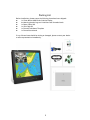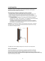
1
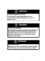
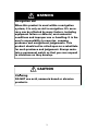
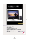
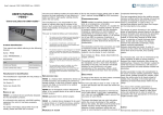
USER MANUAL AWM SERIES II AWM-1510 Marine Monitor AWM-1910 Marine Monitor (1st Edition 8/26/2013) All information contained in this manual is subject to change without notice RECORD OF REVISION Version and Date Page August 26, 2013 all Old Description Release New Description Version 1.0 Remark TABLE OF CONTENT RECORD OF REVISION ....................................................................................................... 0 TABLE OF CONTENT...................................................................................................... 1 WARNING NOTICES........................................................................................................2 IMPORTANT INFORMATION........................................................................................... 4 PACKING LIST...................................................................................................................5 1.0 INTRODUCTION............................................................................................................ 6 2.0 CONTROL AND FEATURES............................................................................................. 7 3.0 INSTALLATIONS ............................................................................................................ 8 4.0 OSD OPERATIONS....................................................................................................... 14 5.0 TECHNICAL SPECIFICATION ........................................................................................ 30 6.0 ORDERING INFORMATION .......................................................................................... 32 7.0 MAINTENAINCE AND TROUBLESHOOTING .................................................................... 34 1 WARNING Potential ignition sources This product is NOT approved for use in hazardous/flammable atmospheres, e.g. an engine room. WARNING Product installation This equipment must be installed and operated in accordance with Green Marine' s instructions provided. Failure to do so could result in poor product performance, personal injury, and/or damage to your boat. WARNING Electrical safety Make sure you have set the boat’s power supply to OFF before you start installing this product. 2 WARNING Navigation aid When this product is used within a navigation system, it is only an aid to navigation. It’s accuracy can be affected by many factors, including equipment failure or defects, environmental conditions and improper use or handling. It is the user’s responsibility to exercise common prudence and navigational judgements. This product should not be relied upon as a substitute for such prudence and judgement. Always maintain a permanent watch so that you can respond to situations as they develop. CAUTION Cleaning DO NOT use acid, ammonia based or abrasive products. 3 IMPORTANT INFORMATION EMC conformance All Green Marine displays and accessories are de signed to the best industry standards for use in the mari ne environment. The design and manufacture of Green Marine displays and accessories conform to the appropriate ElectroMagnetic Compatibility (EMC) standards, but correct installation is required to ensure that performance is not compromised. Waste Electrical and Electronic Equipment Directive The Waste Electrical and Electronic Equipment (WEEE) Directive requires the recycling of waste electrical and electronic equipment. While the WEEE Directive does not apply to some of Green Marine's products, we support its policy and ask you to be aware of how to dispose of our products. The crossed out garbage bin symbol, illustrated above, and found on our products signifies that this product should not be disposed of in general waste or landfill facilities. Please contact the marine electronics dealer you purchased this product from, or Green Marine customer support for information on product disposal. Restriction of the use of certain Hazardous Substances Green Marine displays use components that comply wi th the requirements of the restriction of the use of certain Hazardous Substances (RoHS) Directive 2002/95/ EC. Warranty To register your new Green Marine display, please go to: www.greenmarinemonitors.com It is important that you complete the owner information to receive full warranty benefits, including notification of software updates if they are required. 4 Packing List Before installation, please ensure the following items have been shipped: z 1 x Green Marine AWM Series II Marine Display z 4 x Mounting bracket lugs and 4 stainless steel threaded studs z 1 x Power Cable 10ft z 1 x VGA Cable 9ft z 1 x Printed Flush Mount Template z 1 x Printed User Manual If any of these items should be missing or damaged, please contact your dealer 摡浡来搠灬敡獥潮瑡捴⁹潵爠摥慬敲 or sales representative immediately. 5 1.0 INTRODUCTION About Green Marine AWM Series II Displays Green Marine AWM Series II marine displays are equipped with optically bonded AR glass and are specifically engineered to survive the most demanding applications. You will soon become familiar with the quality difference in this bright, sunlight readable (0 to 1,000 nits) display. The range of AWM Series II Marine Displays has been developed to be used as part of an integrated marine navigation system or within an entertainment system. The displays, available in 15” and 19” sizes, are suitable for use on the flybridge or in the pilot house and are IP-65 waterproof from the front when panel mounted. The AWM Series II displays handle a wide-range of extreme environments making them the industry choice for recreational and commercial marine applications. Housed in a milled billet aluminum case, AWM displays are light weight and are designed with a very slim case profile. Front-mounted controls and a dimming knob insure these displays are user-friendly. We have incorp orated the latest optical engineering to achieve optimal viewability in all lighting conditions, including direct sunlight. The AWM Series' power efficient, low heat design results in increased reliability and longevity required for mission critical deployment. This manual contains important information on the installation, operation and maintenance of your Green Marine AWM Series II marine display(s). 6 2.0 CONTROL AND FEATURES Your AWM Series II marine display has the following controls and features: Front View PIP Display Screen Function Control Power Button Buttons VR Knob Back View FUSE 10A Max 9-36V DVI VGA CVBS RS232 DC 7 3.0 INSTALLATION It is important that your new display is installed and operated in accordance with the instructions provided in this manual. Failure to do so could result in poor product performance and may invalidate your warranty. When planning the installation the following points must be considered: • Your AWM II display is sunlight viewable and visible in direct sunlight.. • If temperatures exceed the normal temperature operating range, the display could overheat and begin to blackout due to the limitations of TFT LCD technology. • In order to minimize the chances of a malfunction, the following precautions should be taken during installation: • The display should be installed in an area where there is proper and adequate ventilation (min. 6 inches / 15cm clearance) . If it is possible to cool the area behind the display, it will significantly reduce the risk of a malfunction. • The display should be mounted at an angle to the sun. We do not recommend mounting the unit in a flat plane, which increases the surface area exposed to the sun and leads to increased heat absorption. IMPORTANT: Your AWM Series II display is only waterproof from the front. To maintain watertight integrity, the display must be flush mounted ensuring that the rear casing is enclosed in a watertight enclosure. The AWM Series II marine display is designed to be mounted in two configurations: VESA75 / VESA100 MOUNT Green Marine AWM Series II marine displays are compatible with VESA75 and VESA100 mounts. By installing the display with a compatable VESA mount the user can change the displays angle to improve viewability. Before the display is mounted, power and signal source should be connected and the display should be held at approximate mounting location to check viewing angle for satisfactory picture quality. 8 Mounting holes built into the back surfaceof the display allow it to be mounted by rear mount using VESA75 or VESA100 compatible mounts. PANEL (Flush) MOUNT For installation, there are four tapped mounting slots on both sides of the display and on the top and bottom. The mounting hardware packet is included with the product accessories in the shipping box. This packet includes four (4) stainless steel threaded studs and four (4) mounting lock nuts. AWM Series II displays can be installed using the mounting lock nuts (supplied) in the vertical keyways. Make sure that both brackets are installed in the same orientation. Preparing the installation site 1. Select an installation site that has sufficient space behind it for cable connections and ventilation. 2. Tape the supplied flush mount template in the required position. 3. Using a jigsaw, carefully remove the shaded portion of the template. 4. Using a suitable file, smooth the edges of the opening. 9 Installing the display 1. Carefully insert the display into the opening so the gasket on the backside of the bezel edge lays flat against the front edge of the cut out. IMPORTANT: The gasket must lay flat against the cut out edge to ensure watertight integrity. Do not over tighten mounting screws. 2. Place the mounting bracket lugs into the keyways and move them to the rear, securing the bracket to the display. 3. Using a suitable screwdriver, tighten the mounting bracket screws to secure the monitor in position and compress the gasket. NOTE: If console is thicker than 6/16 inch (10mm), caps on the ends of the screws may be removed to provide additional clearance 10 4. Connect all cables as required - see “Rear connections” below. Rear connections 1 2 3 4 5 6 7 8 9 10 The rear connectors are: 1. FUSE 2. Power Input 3. DVI-1 Input 4. DVI-2 Input 5. VGA-1 Input 6. VGA-2 Input 7. CVBS-1 Input (Composite Video) for AV input 8. CVBS-2 Input (Composite Video) for AV input 9. CVBS-3 Input (Composite Video) for AV input 10. RS232 Input Planning the installation Before you install your display, the following points should be considered: • Power requirements. • Display location and mounting options. • Additional accessories, e.g. keyboard or speakers. Power requirements Your Sunlight Viewable display is designed to run on boat’s DC power systems rated at 12 V or 24 V. Your AWM Series II display is equipped for a 9~36V DC wide range of power input. The DC power system should be either: • Negative grounded, with the negative battery terminal connected to the boat’s ground, • Floating, with neither battery terminal connected to the boat’s ground. Grounding the display It is important that an effective radio frequency (RF) ground is connected to the display. You can ground the display by connecting the ground wire (gray) of the power input cable to the grounding screw on the back of the display located near the power connector on the display end, and the nearest ground point of the boat's RF ground system on the other end. 11 Display location and mounting options Your display can be mounted using the flush mounting clamps supplied. Green Marine recommends that you power the unit and select a suitable mounting location prior to installing the display. When planning the display location, the following points should be considered to ensure safe, comfortable, and reliable operation: • Convenience- the mounting location should be easily accessible to allow operation of the front control buttons and should enable easy viewing of the display. Power connections The power connection to the display should be made at either the output of the battery isolator switch, or at a DC power distribution panel. Green Marine recommends that power is fed directly to the display via its own dedicated cable system and MUST be protected by a thermal circuit breaker or fuse fitted close to the power connection. If you do not have a thermal circuit breaker or fuse in your power circuit, you MUST fit an in-line breaker or fuse to the positive (red) lead of the power cable. Power connector Grounding screw • Installation angle- the AWM II display should be mounted at an angle. Mounting it in a flat plane is not recommended due to increased heat absorption. • Viewing angle - this LCD has been chosen to give the very best performance, including viewing angle. However, the contrast and colors seen on all LCD displays vary slightly with viewing angle. Before the display is mounted, power and signal source should be connected and display should be held at approximate mounting location to check viewing angle for satisfactory picture quality. • Environment - to prevent overheating, do not restrict airflow at the rear of the display. If the space behind the display is air conditioned or cooled by a fan, it will help in keeping the unit’s temperature down when mounted in direct sunlight. FAILURE TO ADEQUATELY VENTILATE THE UNIT COULD INVALIDATE YOUR WARRANTY. The display should be protected from physical damage and excessive vibration. Although the display is waterproof from the front when installed correctly, it is good practice to mount it in a protected area away from prolonged and direct exposure to rain and salt spray. DO NOT mount the display near a heat source. 12 Typical Installation Diagram Remarks: The real installation diagram above is only for reference and will differ for different kinds of applications. 13 4.0 OSD OPERATIONS Introduction AWM Series II displays can be controlled using the On Screen Display (OSD) menu and/or the 8 buttons on the front bezel of the unit. The OSD menu enables you to change the way in which your display is set up and is accessed using the “OSD” button. Using the buttons Each of the 8 buttons on the front bezel of your display has a control function. The “OSD” button and the down and up arrow buttons have miltiple functions. POWER Power Button On To power your display ON, press the power button one time. There is a few seconds delay before the display turns on.This delay is part of the displays protection against any surge voltage from the engine. Power Button Off To power your display OFF, press the power button again. The same delay occurs before powering down. 14 BRIGHTNESS Button The BRIGHTNESS button is only a backup function in case the VR BRIGHTNESS knob fails. If the VR BRIGHTNESS knob fails to function, you can enable the brightness button by pressing the ''OSD'' button, selecting ''OSD'', selecting ''Brightness'' Then use arrow buttons to change ''VR'' to ''BRILL'' and exit OSD. With "BRILL" enabled, you can now press the BRIGHTNESS button and the brightness bar above will appear. The display brightness can now be controlled with down and up arrow buttons. After you release the “BRIGHTNESS” key around 5 seconds, the brightness bar will disappear. VR BRIGHTNESS Knob Your AWM Series II display is shipped with VR BRIGHTNESS knob function enabled as standard. When you rotate the VR knob, the VR BRIGHTNESS status bar below will appear on screen. (dimming range is from 1~50): (see below) When you enter “NIGHT MODE” turning the VR BRIGHTNESS knob will always take over the brightness function again. The VR BRIGHTNESS knob always supersedes any other brightness setting. Any modified or changed parameter setting will be automatically saved if you power off or Exit the BRIGHTNESS status bar. 15 NIGHT MODE Button When you press the “NIT” button,the display will dim directly to 0.5 nit. Pressing the button a second time dims the display to “black.” The button can now be used to toggle back and forth between .5 nits and black for night viewing. Turning the VR Brightness Knob will over ride NIGHT MODE and return the knob to brightness control. Any modified or changed parameter setting will be automatically saved if you power off or Exit the NIGHT MODE. DOWN UP ARROW Buttons The ARROW buttons work as navigation buttons to move the highlight cursor to the desired selection. The “DN” (left) arrow button can be used to move the hightlight cursor “Down”. The “UP” (right) arrow button can be used to move the hightlight cursor “Up”. SIGNAL INPUT Button When you press the “SIG” button, the screen below will pop up on the display: You can now press the “DN” arrow button to move the highlight cursor ”Down” and and the “UP” arrow button to move the highlight cursor “Up”. If you release the “Arrow” buttons for 5 seconds without any action, the INPUT SELECTION screen will be closed and it will remain at the item which you selected. Any modified or changed parameter setting will be automatically saved if you power off. 16 PIP Button 1. 2. 3. 4. 5. Default Default Default Default Default main main main main main screen screen screen screen screen shows at RGB1 & RGB2Æ Press “PIP” button Æ Figure 1 stays at DVI1 & DVI2Æ Press “PIP” button Æ Figure 2 stays at VIDEO 1Æ Press “PIP” button Æ Figure 3_1 stays at VIDEO 2Æ Press “PIP” button Æ Figure 3_2 stays at VIDEO 3Æ Press “PIP” button Æ Figure 3_3 PIPFunctionSupportingTable Sub RGB1 Main RGB1 ! RGB2 ! DVI1 OK DVI2 OK VIDEO1 OK VIDEO2 OK VIDEO3 RGB2 DVI1 DVI2 ! ! OK OK OK OK OK OK ! OK OK OK OK ! OK OK OK OK OK OK VIDEO1 VIDEO2 VIDEO3 OK OK OK OK ! OK OK OK OK OK OK ! OK OK OK OK OK OK OK OK Figure1 ! Figure1 Figure1 Figure2 Figure2 Figure3_1 Figure3_2 ! Figure3_3 Figure2 Figure3_1 Figure3_2 17 Figure3_3 You can now press the “DN” arrow button to move the highlight cursor ”Down” and and the “UP” arrow button to move the highlight cursor “Up”. If you release the “Arrow” buttons for 5 seconds without any action, the INPUT selection screen will be closed and it will remain at the item which you selected. Any modified or changed parameter setting will be automatically saved if you power off. PIP (1-10) Picture Size You can choose PIP size scaling from 1~10 times and PAP1 (4:3 aspect ratio) or PAP2 (side by side for half full screen). For re-sizing screen, see PIP sub menu setting screen (page 24) PIP Picture Placement When the PIP screen is activated in the main display window, the “DN” and “UP” arrow buttons may be used to move the PIP window around the display screen. The arrow buttons will move the PIP window horizontal until it can move no further, then the PIP window will start moving vertical. In this way the PIP window can be possitioned anywhere on the main display screen. 18 PAP1 (4:3 aspect ratio window) Picture PAP2 (Side by side full screen window) Picture 19 MENU Button When you press the “OSD” button, the OS D main menu screen will appear as below: If you release the “OSD” button for 30 seconds without any action, the menu OSD screen will disappear automatically. You can also choose “QUIT” and then press “OSD” button to exit this OSD menu screen. 20 RGB1 & 2’s setting screen: RGB Setting Item Description: ʳ PHASE Horizontal Sampling Phase AdjustmentΖ ʳ CONTRAST Contrast AdjustmentΖ ʳ H_POSITION Horizontal Screen AdjustmentΖ ʳ V_POSITION Vertical Screen AdjustmentΖ ʳ R_LEVEL Red Color level AdjustmentΖ ʳ G_LEVEL Green Color level AdjustmentΖ ʳ B_LEVEL Blue Color level AdjustmentΖ ʳ TEMPERATURE Color Temperature AdjustmentΖ ʳ DISP MODE ʳ ʳ ʳ ʳ ʳ ʳ ʳ ʳ ʳ FULL Full ScreenΖ ʳ ʳ ʳ ʳ ʳ ʳ ʳ ʳ ʳ EVEN Half ScreenΖ ʳ ʳ ʳ ʳ ʳ ʳ ʳ ʳ ʳ NORMAL Keep normal aspect ratioΖ ʳ AUTO ADJUST Auto adjustmentޕ ʳ EXIT Quit from current settingޕ ʳ 21 DVI 1 & 2’s setting screen: DVI Setting Item Description: ʳ CONTRASTContrast AdjustmentΖ ʳ R_LEVEL Red Color level AdjustmentΖ ʳ G_LEVEL Green Color level AdjustmentΖ ʳ B_LEVEL Blue Color level AdjustmentΖ ʳ TEMPERATURE Color Temperature AdjustmentΖ ʳ DISP MODE ʳ ʳ ʳ ʳ ʳ ʳ ʳ ʳ ʳ FULL Full ScreenΖ ʳ ʳ ʳ ʳ ʳ ʳ ʳ ʳ ʳ EVEN Half ScreenΖ ʳ ʳ ʳ ʳ ʳ ʳ ʳ ʳ ʳ NORMAL Keep normal aspect ratioΖ ʳ EXIT Quit from current settingޕ 22 VIDEO 1, 2 & 3 setting screen: VIDEO Setting Item Description: ʳ CONTRAST Contrast AdjustmentΖ ʳ SHARPNESS Horizontal edge sharpness ʳ HUE Color Adjustment ʳ R_LEVEL Red Color level AdjustmentΖ ʳ G_LEVEL Green Color level AdjustmentΖ ʳ B_LEVEL Blue Color level AdjustmentΖ ʳ TEMPERATURE Color Temperature AdjustmentΖ ʳ EXIT Quit from current settingޕ 23 PIP Sub-menu setting screen: PIP Setting Item Description: ʳ PIP_SIZE Picture in Picture Screen Size AdjustmentΖ ʳ CONTRAST Contrast AdjustmentΖ ʳ R_LEVEL Red Color level AdjustmentΖ ʳ G_LEVEL Green Color level AdjustmentΖ ʳ B_LEVEL Blue Color level AdjustmentΖ ʳ EXIT Quit from current settingޕ 24 OSD Setting Main Screen: OSD Setting Item Description: ʳ H_POSITION Horizontal Screen AdjustmentΖ ʳ V_POSITION Vertical Screen AdjustmentΖ ʳ TRANSLUCENT Screen background color can be adjusted as transparent as you want (total 10 scales)Ζ ʳ BRIGHTNESS Selection between “BRT” button or “VR” k n o b for brightness adjustment.Ζ(Note: VR knob is factory setting) ʳ SYSTEM RETURN Restore all parameter setting to factory default valueΖ ʳ EXIT Quit from current settingޕ 25 Programmable OSD Signal Input Source Name setting screen: 1. Press the “DN/UP” arrow buttons to move to the desired input name. 2. Press the “OSD” button to rename “RGB1” to any desired source input name. Example: Sonar, Radar…etc). Press the “DN/UP” arrow buttons to select from (A~Z, 0~9, “.”, “-“) characters. When correct character is selected, just press the “OSD” button to move to the next character step by step. 26 3. Below is a picture of renaming RGB1 channel to “RADAR” SYSTEM RETURN setting screen: 27 You may choose “SYSTEM RETURN” selection item on the OSD Screen to restore all of the parameter settings to factory default value. When you press the “UP” arrow button, the parameter will show “YES” and confirm it. 28 “BUTTON LOCK” Mode Function setting screen: When you press “OSD” and “BRT” buttons simultaneously for 3 seconds, you will enter the “KEY LOCK” mode. At the same time, the screen will show “KEY LOCK” image as below for 5 seconds and then disappear. In the “KEY LOCK” mode, none of the buttons will function when pressed. To Release/Unlock “BUTTON LOCK” Mode Function setting screen: In the “BUTTON LOCK” mode, when you press “OSD” and “BRT” buttons simultaneously for 3 seconds, you will release/unlock the “BUTTON LOCK” mode. At the same time, your screen will show “KEY UNLOCK” image as below. 29 6.2 Specification- AWM-1510 LCD Display Backlight 15 inch LED Backlight Active Display Area Brightness 304.128 x 228.096 mm Resolution 1024x768 (XGA) Contrast Ratio Pixel Pitch (mm) 700:1 0.297(H) x 0.297 (V) Viewing Angle 160 (H), 160(V) Display Color 16.2M Response Time Tr:8ms, Tf:17ms Inputs VGAx2, DVIx2, Composite x3, RS232x1 Picture in Picture 3 stages 1000 cd/m2 * Mechanical IP Rating Facial waterproof to IP65 standards when console mounted. Construction Rugged Aluminum Alloy Chassis Mounting Panel (Flush) mount, VESA mount Dimension 352.8(W)x303.3(H)x56(D) mm Power Voltage Operates on 12V and 24V systems Power Consumption 30-35W / 2.9A (12V) Environmental Operating Temperature -20°C~60°C Non-Operating Temperature -20°C~70°C Certification Designed to meet FCC Class A, Designed to meet EN60945 * The brightness is measured under the 25°C ambient temperature. Due to panel material's deviation, different panel suppliers will set different specific variance range to optical characteristics. The factors of time used, Lamp current, ambient temperature will influence the optical measurements. 30 6.4 Specification- AWM-1910 LCD Display Backlight 19 inch LED Backlight Active Display Area Brightness 376.32 x 301.06mm Resolution 1280x1024 (SXGA) Contrast Ratio Pixel Pitch (mm) 900:1 0.294(H) x 0.294 (V) Viewing Angle 160 (H), 160(V) Display Color 16.2M Response Time Tr:3.6ms, Tf1.4ms Inputs VGAx2, DVIx2, Composite x3, RS232x1 Picture in Picture 3 stages 1000 cd/m2 * Mechanical IP Rating Facial waterproof to IP65 standards when console mounted. Construction Rugged Aluminum Alloy Chassis Mounting Panel (Flush) mount, VESA mount Dimension 421.9(w)x375.5(H)x56(D) mm Power Voltage Operates on 12V and 24V systems Power Consumption 40-45W / 3.8A (12V) Environmental Operating Temperature -10°C~50°C Non-Operating Temperature -20°C~70°C Certification Designed to meet FCC Class A, Designed to meet EN60945 * The brightness is measured under the 25°C ambient temperature. Due to panel material's deviation, different panel suppliers will set different specific variance range to optical characteristics. The factors of time used, Lamp current, ambient temperature will influence the optical measurements. 31 6.0 ORDERING INFORMATION Model Number Description AWM-1510 15” Sunlight readable LCD, Optical bonded AR glass, 9~36V DC wide range input power, dim to black, seven signal inputs AWM-1910 19” Sunlight readable LCD, Optical bonded AR glass, 9~36V DC wide range input power, picture-in-picture, dim to black, seven signal inputs 32 6.0 MAINTENAINCE AND TROUBLESHOOTING Precautions To maximize the life and safe use of your unit, always be sure to follow the warnings, precautions and maintenance recommendations in this user manual. In a Watercraft or Vehicle: z The display should be visible to the driver only if it is used for navigation, or system control. Care should be taken to ensure distraction does not occur. z Review all applicable federal, state and local laws and regulations to make sure the display is used properly and safely. z Avoid using the display for extended times while the charging system is not running, or the display could drain the watercraft’s battery. Maintenance High Voltage W A R N IN G ! The display unit contains high voltages. 01. To reduce the risk of electric shock, do not remove the cover or back. There are no user-serviceable parts inside. 02. Make sure you turn off and unplug the display before installing devices. Cleaning the display CAUTION! Cleaning Glass DO NOT use acid, ammonia based or abrasive products. Use only soft cloth moistened with isopropyl alcohol to clean anti-reflective glass. Cleaning the metal case 1. Use a soft cloth moistened with mild detergent, isopropyl alcohol, or window cleaners to clean the metal display housing . 2. If necessary use isopropyl alcohol or a mild detergent to remove grease marks and fingerprints. 3. Never use abrasive cleaners, waxes or solvents to clean the unit or powder coat finish could be damaged Disconnecting the power supply To disconnect the display from the boat’s power supply either; • Isolate the power cable from the main supply, or, • Remove the power connector from the rear of the display. The power button on the front of the display changes the operating mode; it does not provide complete protection in an emergency 33 Troubleshooting All Green Marine AWM Series II displays are, prior to packing and shipping, subjected to comprehensive test and quality assurance programs. However, if this unit should develop a fault, please refer to the following table to identify the most likely cause and the corrective action required to restore normal operation. If you still have a problem after referring to the table below, contact the marine electronics dealer from who you purchased the product, or contact Green Marine Monitors by clicking on the ''Customer Support'' tab of our web site at www.greenmarinemonitors.com. Common problems and their solutions Problem Solution The display is very dim or dark Adjust the display as described in “Image adjustment on ” Section 5 OSD Menu. The display shows the message ‘No Input’ Check that the video source i.e. display, camera, DVD etc. is powered and that the cables are correctly connected. You have pressed the power button, but the display does not function. 1. Make sure that the power cable is well connected and that all connections are tight and free from corrosion. 2. Check the system fuse. 34