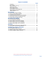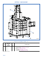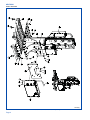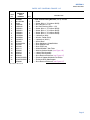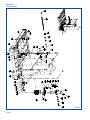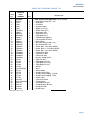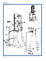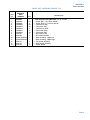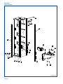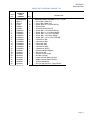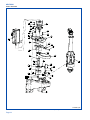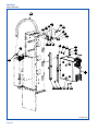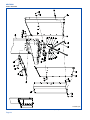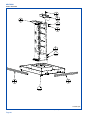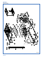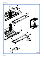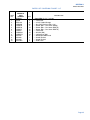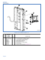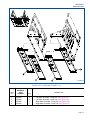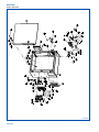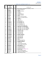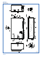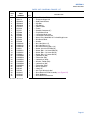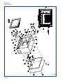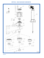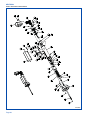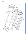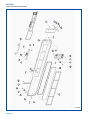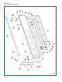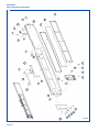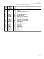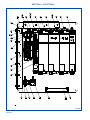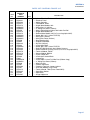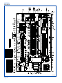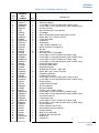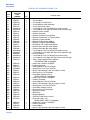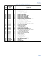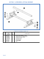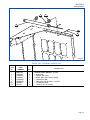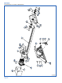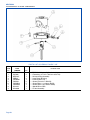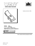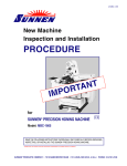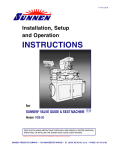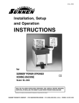
1
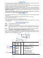
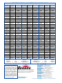
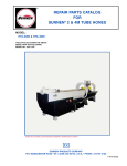
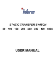
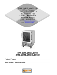
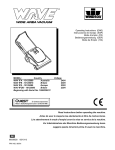
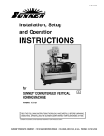
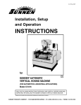
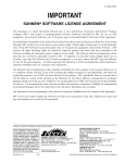
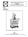
REPAIR PARTS CATALOG
FOR
SUNNEN® CNC VERTICAL HONING MACHINE
MODEL:
SV2560
“SUNNEN® AND THE SUNNEN LOGO ARE REGISTERED TRADEMARKS OF SUNNEN PRODUCTS COMPANY.”
SUNNEN® PRODUCTS COMPANY
7910 MANCHESTER ROAD • ST. LOUIS, MO 63143, U.S.A. • PHONE: 314-781-2100
X-SV-5605
Like any machinery, this equipment may
be dangerous if used improperly. Be
sure to read and follow instructions for
operation of equipment.
ii
INTRODUCTION
Illustrations show all major components in exploded detail. Item numbers on each illustration are keyed to
the corresponding parts list, providing a descriptive identification of each part.
The parts lists include assemblies as well as detail parts. An item listed without a part number can be
obtained as a component of the complete assembly of which it is a part.
Standard hardware items are listed with complete descriptions, such as Item 29 below. These may be
purchased at your local hardware store, but it is important to replace an item with one having the same
dimensions as the original. In some places brand names and part numbers are shown. These may change
depending upon availability.
Sunnen Products Company reserves the right to make changes, without notice, to materials,
specifications, colors, designs and accessories included with units.
HOW TO ORDER
When ordering replacement parts be sure to include the following information to ensure prompt shipment of
correct parts:
1. The part number and description of each part desired, obtained from this parts catalog.
2. The quantity of each part desired.
3. The voltage, frequency and phase, when ordering electrical parts.
4. The model and serial number of the machine, obtained from the name plate, where there is any question
concerning a part.
HOW TO USE THIS PARTS LIST
Step 1. – Locate desired part on illustration. Note item number.
Step 2. – Locate item number in the parts list.
Step 3. – If the item has a part number listed, order by part number and the description. A part number in
light face type indicates that it is a component of the last preceding part number in bold face
type.
Step 4. – If no number is listed, order the part number of the unit of which the desired part is a component.
ORDER ONLY BY PART NUMBER AND DESCRIPTION – NOT by item number.
NOTE: In this manual, parts may be followed by “(For CE Machines)” or “(For Non-CE Machines)” to denote
domestic machines from exported machines. The CE version is constructed to meet the requirements of the
European market, and is available to any customer.
1
Step 1.
4
2
3
15
17
14
Step 2.
Step 3.
Step 4.
ITEM
NO.
ORDER BY
PART
NUMBER
QTY.
1
2
3
4
MVH-4499A
PHSM-405
PHW-354
MVH-4422
1
3
3
1
....Spindle Cap includes
......Screw (M6 x 1 x 16 SHCS)
......Washer (M6)
....Inner Spindle Nose
14
15
16
17
PEM-870A
PEM-871
PEM-872
PHSM-600
1
1
1
1
....Cable Carrier includes
......Cable Carrier Bracket
......Cable Carrier Bracket
....Screw (M3 x 0,5 x 5mm FHCS)
iii
DESCRIPTION
GENERAL INFORMATION
The Sunnen® equipment has been designed and engineered for a wide variety of parts within the capacity and limitation of the equipment. With proper care
and maintenance this equipment will give years of service.
READ THE FOLLOWING INSTRUCTIONS CAREFULLY AND THOROUGHLY BEFORE UNPACKING, INSPECTING, OR INSTALLING THIS
EQUIPMENT.
IMPORTANT: Read any supplemental instructions BEFORE installing this equipment. These supplemental instructions give you important information to
assist you with the planning and installation of your Sunnen equipment.
Sunnen Technical Service Department is available to provide telephone assistance for installation, programming, & troubleshooting of your Sunnen
equipment. All support is available during normal business hours, 8:00 AM to 4:30 PM Central Time. Emergency breakdown support is available on a 24
hour / 7 day basis.
Review all literature provided with your Sunnen equipment. This literature provides valuable information for proper installation, operation, and maintenance
of your equipment. Troubleshooting information can also be found within the Instructions. If you cannot find what you need, call for technical support.
Where applicable, programming information for your Sunnen equipment is also included. Most answers can be found in the literature packaged with your
equipment.
Help us help you. When ordering parts, requesting information, or technical assistance about your equipment, please have the following
information available:
• Have ALL MANUALS on hand. The Customer Services Representative or Technician will refer to it.
• Have Model Number and Serial Number printed on your equipment Specification Nameplate.
• Where Applicable: Have Drive model and all nameplate data. Motor type, brand, and all nameplate data.
For Troubleshooting, additional information may be required:
• Power distribution information (type - delta, wye, power factor correction; other major switching devices used, voltage fluctuations)
• Installation Wiring (separation of power & control wire; wire type/class used, distance between drive and motor, grounding).
• Use of any optional devices/equipment between the Drive & motor (output chokes, etc.).
For fast service on your orders call:
Sunnen Automotive Customer Service toll free at: 1-800-772-2878
Sunnen Industrial Customer Service toll free at: 1-800-325-3670
Customers outside the USA, contact your local authorized Sunnen Distributor.
Additional information available at: http://www.sunnen.com or e-mail: [email protected]
NOTE: Sunnen reserves the right to change or revise specifications and product design in connection with any feature of our products contained herein.
Such changes do not entitle the buyer to corresponding changes, improvements, additions, or replacements for equipment, supplies or accessories
previously sold. Information contained herein is considered to be accurate based on available information at the time of printing. Should any discrepancy of
information arise, Sunnen recommends that user verify the discrepancy with Sunnen before proceeding.
ESD PREVENTION REVIEW
Let's review the basics of a sound static control system and its effective implementation. First, in the three step plan:
1.
Always ground yourself when handling sensitive components or assemblies.
2.
Always use a conductive or shielded container during storage or transportation. These materials create a Faraday
cage which will isolate the contents from static charges.
3.
Open ESD safe containers only at a static safe work station.
At the static safe work station, follow these procedures before beginning any work:
A.
Put on your wrist strap or foot grounding devices.
B.
Check all grounding cords to make sure they are properly connected to ground, ensuring the effective dissipation of static charges.
C.
Make sure that your work surface is clean and clear of unnecessary materials, particularly common plastics.
D.
Anti-static bubble wrap has been included for use at the machine when an ESD safe workstation is not available.
You are now properly grounded and ready to begin work. Following these few simple rules and using a little common sense will go a long
way toward helping you and your company in the battle against the hazards of static electricity. When you are working with ESD sensitive devices, make sure you:
GROUND
ISOLATE
NEUTRALIZE
iv
SUNNEN® LIMITED PRODUCT WARRANTY
Sunnen® Products Company and its subsidiaries (SPC) warrant that all new SPC honing machines, gaging equipment, tooling, and related equipment will
be free of defects in material and/or workmanship for a period of one year from the date of original shipment from SPC.
Upon prompt notification of a defect during the one-year period, SPC will repair, replace, or refund the purchase price, with respect to parts that prove to be
defective (as defined above). Any equipment or tooling which is found to be defective from improper use will be returned at the customer's cost or repaired
(if possible) at customer's request. Customer shall be charged current rates for all such repair.
Prior to returning any SPC product, an authorization (RMA#) and shipping instructions must be obtained from the Customer Service Department or items
sent to SPC will be returned to the customer.
Warranty Limitations and Exclusions This Warranty does not apply to the following:
• Normal maintenance items subject to wear and tear: (belts, fuses, filters, etc).
• Damages resulting from but not limited to:
› Shipment to the customer (for items delivered to customer or customer's agent F.O.B., Shipping Point)
› Incorrect installation including improper lifting, dropping and/or placement
› Incorrect electric power (beyond +/- 10% of rated voltage) including intermittent or random voltage spikes or drops
› Incorrect air supply volume and/or pressure and/or contaminated air supply
› Electromagnetic or radio frequency interference from surrounding equipment (EMI, RFI)
› Storm, lightning, flood or fire damage
› Failure to perform regular maintenance as outlined in SPC manuals
› Improper machine setup or operation causing a crash to occur
› Misapplication of the equipment
› Use of non-SPC machines, tooling, abrasive, fixturing, coolant, repair parts, or filtration
› Incorrect software installation and/or misuse
› Non-authorized customer installed electronics and/or software
› Customer modifications to SPC software
THE LIMITED WARRANTY DESCRIBED HEREIN IS EXPRESSLY IN LIEU OF ALL ANY OTHER WARRANTIES. SPC MAKES NO REPRESENTATION OR WARRANTY OF
ANY OTHER KIND, EXPRESS OR IMPLIED, WHETHER AS TO MERCHANTABILITY, FITNESS FOR A PARTICULAR PURPOSE OR ANY OTHER MATTER. SPC IS NOT
RESPONSIBLE FOR THE IMPROPER USE OF ANY OF ITS PRODUCTS. SPC SHALL NOT BE LIABLE FOR DIRECT, INDIRECT, INCIDENTAL, OR CONSEQUENTIAL
DAMAGES INCLUDING BUT NOT LIMITED TO: LOSS OF USE, REVENUE, OR PROFIT. SPC ASSUMES NO LIABILITY FOR PURCHASED ITEMS PRODUCED BY OTHER
MANUFACTURERS WHO EXTEND SEPARATE WARRANTIES. REGARDLESS OF ANY RIGHTS AFFORDED BY LAW TO BUYER, SPC's LIABILITY, IF ANY, FOR ANY AND
ALL CLAIMS FOR LOSS OR DAMAGES WITH RESPECT TO THE PRODUCTS, AND BUYER'S SOLE AND EXCLUSIVE REMEDY THEREFORE, SHALL IN ALL EVENTS BE
LIMITED IN AMOUNT TO THE PURCHASE PRICE OF THAT PORTION OF THE PRODUCTS WITH RESPECT TO WHICH A VALID CLAIM IS MADE.
Shipping Damages
Except in the case of F.O.B., Buyer's destination shipments, SPC will not be liable for any settlement claims for obvious and/or concealed shipping damages.
The customer bears the responsibility to unpack all shipments immediately and inspect for damage. When obvious and/or concealed damage is found, the
customer must immediately notify the carrier's agent to make an inspection and file a claim. The customer should retain the shipping container and packing
material.
SUNNEN® SOFTWARE LICENSE AGREEMENT
This document is a Legal Agreement between you, as user and licensee (Licensee), and Sunnen® Products Company (SPC) with respect to preprogrammed
software (Software) provided by SPC for use on SPC Equipment. By using the Software, you, as Licensee, agree to become bound by the terms of this
Agreement.
In consideration of payment of the license fee (License Fee) which is part of the price evidenced by your receipt (Receipt), SPC grants to you as Licensee
a non-exclusive right, without right to sub-license, to use the particular copy of the SPC Software licensed hereunder only on the particular equipment sold with
the Software. SPC reserves all rights including rights not otherwise expressly granted, and retain title and ownership to the Software including all subsequent copies or updates in any media. The Software and all accompanying written materials are covered by copyrights owned by SPC. If supplied on
removable media (floppy disk), you, as Licensee, may copy the Software only for back up purposes; or you may request that SPC copy the Software for you
for the same purposes. All other copying of the Software or of the accompanying written materials is expressly forbidden and is in violation of the Agreement.
The Software and accompanying written materials (including the user's manual, if any) are provided in an "as is" condition without warranty of any kind
including the implied warranties of merchantability and fitness for a particular purpose, even if SPC has been advised of this purpose. SPC specifically does
not warrant that it will be liable as a result of the operation of the Software for any direct, indirect, consequential or accidental damages arising out of the
use of or inability to use such product even if SPC has been advised of the possibility of such use. It is recognized that some states do not allow the exclusion or limitation of liability for consequential or accidental damages and to the extent this is true, the above limitations may not apply.
Any alteration or reverse engineering of the software is expressly forbidden and is in violation of this agreement.
SPC reserves the right to update the software covered by this agreement at any time without prior notice and any such updates are covered by this
agreement.
v
GENERAL SAFETY INSTRUCTIONS
READ FIRST
This machine, like any equipment, may be dangerous if used improperly. Please
read all warnings and instructions before attempting to use this machine.
Always disconnect power at main enclosure before servicing machine.1
Always wear eye protection when operating this machine.
NEVER open or remove any machine cover or protective guard with power "ON."
Always disconnect power at main enclosure before servicing this equipment.1
DO NOT attempt any repair or maintenance procedure beyond those described in
this book. Contact your Sunnen® Field Service Engineer or Technical Services
Representative for repairs not covered in these instructions.
Due to the wide variety of machine configurations, all possibilities cannot be
described in these instructions. Instructions for safe use and maintenance of
optional equipment ordered through Sunnen, will be provided through separate
documentation and/or training provided by your Sunnen Field Service Engineer or
Technical Services Representative.
DO NOT attempt to defeat any safety device on this machine or on any of the
optional equipment.
1
WARNING: DO NOT touch electrical components until main input power has been turned off and CHARGE lamps are extinguished.
The capacitors are still charged and can be quite dangerous.
IMPORTANT NOTE
The temperature requirements of the Sunnen® SV-2560 CNC Vertical Honing Machine have been established
as 35 degrees C (95 degrees F). Above this temperature, an optional cooler will be available to handle
temperatures from 35º to 46º C (95º to 115º F). IT IS NOT recommended that the SV Machine be operated
at temperatures above 46º C (115º F). Sunnen Products Company warrants the SV Machine for operating
environments up to 35ºC (95º F). For operating environments of 35º to 46º C (95º to 115º F) the warranty
only applies if the optional cooler is installed on the Machine. No warranty coverage is offered for operating
environments above 46º C (115º F).
vi
TABLE OF CONTENTS
Introduction .........................................................................................................
How To Order .....................................................................................................
How To Use This Parts List ................................................................................
General Information ............................................................................................
ESD Prevention Review .....................................................................................
Limited Product Warranty ...................................................................................
Sunnen Software License Agreement .................................................................
General Safety Instructions..................................................................................
Table of Contents.................................................................................................
BASIC MACHINE
1-A Vertical Honing Machine (SV2560) .....................................................................
1-B Machine Column Module (SV52605) ..................................................................
1-C Guard Set Assembly (SV54430) .........................................................................
1-D Column Electrical Enclosure Assembly (SV22930) ............................................
1-E Base Electrical Enclosure Assembly (SV53940) ................................................
1-F Operator Station Assembly (SV24580) ...............................................................
BASIC MACHINE COMPONENTS
2-A Spindle Assembly (SV53600) .............................................................................
2-B Linear Feed System (SV53050) .........................................................................
2-C Door Assembly, Left Panel One (SV24450) .......................................................
2-D Door Assembly, Left Panel Two (SV24460) .......................................................
2-E Door Assembly, Right Panel One (SV24465) .....................................................
2-F Door Assembly, Right Panel Two (SV24470) .....................................................
ELECTRICAL
3-A Column Electrical Enclosure Assembly (SV22940) ............................................
3-B Base Electrical Panel Assembly (SV25615) .......................................................
ACCESSORIES & OPTIONAL COMPONENTS
4-A Fixture, Optional (SV21110) ...............................................................................
4-B Light Option Kit, Optional (SV35933) .................................................................
4-C Rollover Cradle Assembly, Optional (SV26200) .................................................
4-G MPS Drive Adapter, Optional (SV23610) ...........................................................
PAGE
iii
iii
iii
iv
iv
v
v
vi
1
2
10
22
28
30
32
34
36
38
40
42
44
46
48
52
53
54
56
“SUNNEN® AND THE SUNNEN LOGO ARE REGISTERED TRADEMARKS OF SUNNEN PRODUCTS COMPANY.”
© Copyright 2013 by Sunnen® Products Company • Printed in U.S.A.
Page 1
SECTION 1 - BASIC MACHINE
1
4
3
2
FIGURE 1-A – CNC VERTICAL HONING MACHINE (1 OF 5)
PARTS LIST COVERING FIGURE “1-A”
ITEM
NO.
1
2
3
4
ORDER BY
PART
NUMBER
SV2560
---------
N/S indicates Not Shown
Page 2
QTY.
Ref
1
1
1
1
DESCRIPTION
....CNC Vertical Honing Machine (1 of 5) includes
......Column & Riser (see Figure 1-A, 3 of 5)
......Base (see Figure 1-A, 4 of 5)
......Guard Sets (see Figure 1-A, 4 of 5)
......Guard, Rear (see Figure 1-A, 5 of 5)
SV2560_1
SECTION 1
BASIC MACHINE
SV2560_3
FIGURE 1-A – CNC VERTICAL HONING MACHINE (2 OF 5)
PARTS LIST COVERING FIGURE “1-A”
ITEM
NO.
1
2
3
4
5
6
7
8
9
10
11
12
ORDER BY
PART
NUMBER
SV2560-3
AN13B
PHNM436
PHSM405
PHSM749
PHSM965
PHWM407
PHWM509
PHWM530
PHWM532
SV24286
SV54023
SV54430
QTY.
12
26
12
14
26
26
12
14
19
1
26
1
DESCRIPTION
....CNC Vertical Honing Machine (2 of 5) includes
......Flatwasher (.257 ID x .750 OD x .065)
......Nut, Self Clinching (M6 x 1,0)
......Screw (M6 x 1,0 x 16mm SHCS)
......Screw (M6 x 1,0 x 12mm BSHCS)
......Screw (M8 x 1,25 x 20mm SHCS)
......Lockwasher (M8)
......Lockwasher (M6)
......Washer, Fender (M6)
......Flatwasher (M8)
......Drip Edge
......Washer
......Guard Set Assembly (see Figure 1-C)
N/S indicates Not Shown
Page 3
SECTION 1
BASIC MACHINE
SV2560_1
FIGURE 1-A – CNC VERTICAL HONING MACHINE (3 OF 5)
Page 4
SECTION 1
BASIC MACHINE
PARTS LIST COVERING FIGURE “1-A”
ITEM
NO.
ORDER BY
PART
NUMBER
QTY.
1
2
3
4
5
6
7
8
9
10
11
12
13
14
15
16
17
18
19
20
21
22
-
SV2560-1
86114SV460
HL639
PHNM406
PHNM494
PHSM453
PHSM454
PHSM480
PHSM684
PHWM408
PHWM542
PHWM573
SV51001
SV51020SV2560
SV51061
SV51062
SV51117
SV52605
SV53515
SV53520
SV53940
SV54035SV1052BH
SV54037SV1052BH
SV26000
1
4
6
8
14
44
6
8
14
20
12
1
1
1
1
1
1
4
4
1
1
2
1
DESCRIPTION
....CNC Vertical Honing Machine (3 of 5) includes
......Cable
......Screw (M12 x 1,75 x 30mm SHCS)
......Nut, Hex (M12 x 1,75)
......Nut, Self Clinching (M12 x 1,75)
......Screw (M12 x 1,75 x 45mm SHCS)
......Screw (M12 x 1,75 x 55mm SHCS)
......Screw (M12 x 1,75 x 65mm SHCS)
......Screw (M12 x 1,75 x 35mm HHCS)
......Lockwasher (M12)
......Washer, Fender (M12)
......Lockwasher (M12,7)
......SV310 Base
......Riser Weldment, SV360/SV2560
......Riser Support Plate
......Riser Foot Plate
......SV360/SV2560 T-Slot Table
......Machine Column Module (see Figure 1-B)
......100mm Foot Assembly
......150mm Foot Assembly
......Base Electrical Enclosure (see Figure 1-E)
......Electrical Support Weldment For SV500
......Enclosure Riser Side Support
......Base Electrical Enclosure (see Figure 1-E)
N/S indicates Not Shown
Page 5
SECTION 1
BASIC MACHINE
SV2560_4
FIGURE 1-A – CNC VERTICAL HONING MACHINE (4 OF 5)
Page 6
SECTION 1
BASIC MACHINE
PARTS LIST COVERING FIGURE “1-A”
ITEM
NO.
1
2
3
4
5
6
7
8
9
10
11
12
13
14
15
16
17
18
19
20
21
22
23
24
25
26
28
29
30
31
32
33
34
35
36
37
38
39
ORDER BY
PART
NUMBER
SV2560-4
CK1328
F1420
F1649
F2855
F3373
F4573GH2
F46959
MAN1079
MB2228SF
PHM464
PHM520
PHM618
PHNM436
PHNM483
PHSM405
PHSM480
PHSM966
PHWM408
PHWM509
PHWM541
PHWM542
PPP201
PPP333
PPP394
PPP396
PPP495
PPP774SV1052BH
PPP775
PPP776
PPP779
PPP780
PPP784
SV21099
SV21111SV2560
SV24189
SV24194
SV24282
SV51298
QTY.
1
1
1
5
1
1
1
2
2
25
1
2
7
5
8
2
4
2
8
4
2
1
2
1
1
1
1
1
1
1
1
1
1
1
1
1
1
1
DESCRIPTION
....CNC Vertical Honing Machine (4 of 5) includes
......Pipe Hex Bushing (3/4" x 1/2)
......Barb Hose
......Valve Ball
......Conduit Hanger
......Nipple (1-1/4 x 2)
......Check Valve (3/4")
......Barb Hose (3/4")
......Pipe Elbow (3/4")
......Pipe Nipple (3/4")
......Flexible Hose Segment
......Loc-Line Shut Off Valve
......Hose Clamp
......Nut, Self Clinching (M6 x 1,0)
......Nut, Knurled (M6 x 10)
......Screw (M6 x 1,0 x 16mm SHCS)
......Screw (M12 x 1,75 x 65mm SHCS)
......Screw (M6 x 1,0 x 25mm SHCS)
......Lockwasher (M12)
......Lockwasher (M6)
......Flatwasher (M6)
......Washer, Fender (M12)
......Pipe Tee (3/4")
......Pipe Nipple (3/4 x 6")
......Pipe Nipple (3/4 x 22")
......Pipe Nipple (3/4 x 2")
......Nozzle
......Hose
......Spray Nozzle
......Garden Hose Fitting
......Garden Hose Coupling - Female
......Garden Hose Coupling - Male
......Check Valve
......Level Limit Switch
......Pump Screen
......Level Switch Bracket
......Pump Mounting Bracket
......Hanger Bracket
......Sump Pump
N/S indicates Not Shown
Page 7
SECTION 1
BASIC MACHINE
SV2560_2
FIGURE 1-A – CNC VERTICAL HONING MACHINE (5 OF 5)
Page 8
SECTION 1
BASIC MACHINE
PARTS LIST COVERING FIGURE “1-A”
ITEM
NO.
ORDER BY
PART
NUMBER
QTY.
1
2
3
4
5
6
7
8
9
10
11
12
13
14
SV2560-2
PHSM405
PHSM606
PHWM509
PHWM518
PHWM521
PHWM531
PHWM534
SV24287
SV24288
SV54014SV2560
SV54016SV2560
SV54121
SV54122
SV54123
24
4
24
10
4
4
14
1
1
1
1
1
1
2
DESCRIPTION
....CNC Vertical Honing Machine (5 of 5) includes
......Screw (M6 x 1,0 x 16mm SHCS)
......Screw (M10 x 1,5 x 25mm SHCS)
......Lockwasher (M6)
......Flatwasher (M6)
......Lockwasher (M10)
......Flatwasher (M10)
......Flatwasher (M6)
......Base Cover Top
......Base Cover Bottom
......Rear Guarding - Upper Left
......Rear Guarding - Upper Right
......Left Guard (SV2560)
......Right Guard (SV2560)
......Guard Spacer
N/S indicates Not Shown
Page 9
SECTION 1
BASIC MACHINE
SV52605op10
FIGURE 1-B – MACHINE COLUMN ASSEMBLY (1 OF 6)
Page 10
SECTION 1
BASIC MACHINE
PARTS LIST COVERING FIGURE “1-B”
ITEM
NO.
1
2
3
4
5
6
7
8
9
10
11
12
13
14
15
16
17
18
19
20
21
22
23
24
ORDER BY
PART
NUMBER
SV52605op10
CBL511
CBL512
F1400
PBR309
PES690
PHSM444
PHSM453
PHSM466
PHSM534
PHSM555
PHWM407
PHWM509
PHWM518
PHWM532
PHWM572
PHWM573
SV02008
SV05001
SV05009
SV22044
SV22063
SV32062
SV52061
SV52301
QTY.
1
1
16
4
2
50
4
1
16
1
51
16
16
50
16
4
2
1
2
1
1
1
2
1
DESCRIPTION
....Machine Column Assembly (2 of 6) includes
......Prox Cable, Lower Limit
......Prox Cable, Upper Limit
......Screw (M10 x 1,5 x 50mm SHCS)
......Runner Block
......Proximity Switch PNP NC
......Screw (M8 x 1,25 x 40mm SHCS)
......Screw (M12 x 1,75 x 45mm SHCS)
......Screw (M6 x 1,0 x 6mm CPSHSS)
......Screw (M6 x 1,0 x 20mm SHCS)
......Screw (M8 x 1,25 x 12mm CPSHSS)
......Lockwasher (M8)
......Lockwasher (M6)
......Flatwasher (M6)
......Flatwasher (M8)
......Lockwasher (M10)
......Lockwasher (M12,7)
......Column Side Rail Support
......SV Column AG
......Column Vertical Guide
......Ball Nut Carriage
......Lower Proximity Switch Bracket
......Upper Proximity Switch Bracket
......Overtravel Stop Bar
......SV Carriage Aluminum, Large Column
N/S indicates Not Shown
Page 11
SECTION 1
BASIC MACHINE
SV52605op20
FIGURE 1-B – MACHINE COLUMN ASSEMBLY (2 OF 6)
Page 12
SECTION 1
BASIC MACHINE
PARTS LIST COVERING FIGURE “1-B”
ITEM
NO.
1
2
3
4
5
6
7
8
9
10
11
12
13
14
15
16
17
18
19
20
21
22
23
24
25
26
27
28
29
ORDER BY
PART
NUMBER
SV52605op20
F2760
PBR310
PBR316
PHM568
PHM569
PHM581
PHNM421
PHRM321
PHSM443
PHSM458SF
PHSM474
PHSM496
PHSM498
PHSM775
PHSM965
PHWM407
PHWM521
PHWM532
PHWM552
PHWM554
PMO1008
PPPM564
SV02011SV2560
SV02071
SV05004
SV05013
SV32069SV1052BH
SV52056
SV52070
QTY.
4
1
1
1
1
2
4
1
1
6
4
4
8
8
4
8
4
4
6
6
1
1
1
1
1
2
1
1
1
DESCRIPTION
....Machine Column Assembly (1 of 6) includes
......Dowel Pin
......Angular Thrust Contact Bearing
......Needle Roller Bearing
......Bellows Coupler
......Precision Locknut
......Lifting Eye Bolt
......Nut, Insert (M10 x 1,8)
......Retaining Ring
......Screw (M8 x 1,25 x 35mm SHCS)
......Screw (M16 x 2,0 x 50mm HHCS)
......Screw (M8 x 1,25 x 45mm SHCS)
......Screw (M10 x 1,5 x 40mm HHCS)
......Screw (M8 x 1,25 x 30mm HHCS)
......Screw (M8 x 1,25 x 55mm SHCS)
......Screw (M8 x 1,25 x 20mm SHCS)
......Lockwasher (M8)
......Lockwasher (M10)
......Flatwasher (M8)
......Lockwasher (M16)
......Flatwasher (M16)
......Blower Cooled Servo Motor
......Straight Male Connector
......Floating Gearing Support
......Lube Adapter
......Support Plate, X-Axis
......Spacer Block
......Stroker Motor Base Plate, Special For SV1052BH
......Grease Deflector
......Ballscrew Assembly
N/S indicates Not Shown
Page 13
SECTION 1
BASIC MACHINE
SV52605op30
FIGURE 1-B – MACHINE COLUMN ASSEMBLY (3 OF 6)
Page 14
SECTION 1
BASIC MACHINE
PARTS LIST COVERING FIGURE “1-B”
ITEM
NO.
1
2
3
4
5
6
7
8
9
10
11
12
13
14
15
16
17
18
19
20
21
22
23
24
25
26
27
28
29
30
31
32
33
34
35
ORDER BY
PART
NUMBER
SV52605op30
PBR355
PDB343
PED2191
PHM623
PHM836
PHM843
PHNM408
PHRM316
PHSM401
PHSM425
PHSM515
PHSM534
PHSM595
PHSM959
PHSM975
PHSM976
PHSM1090
PHWM407
PHWM501
PHWM509
PHWM521
PHWM531
PHWM552
PMO1009
PPPM547
PPPM618
SV53011
SV53013
SV53014
SV53018
SV53019
SV53021
SV53022
SV53600
SV57004
QTY.
1
1
1
1
1
1
1
1
2
4
6
4
4
6
1
1
4
6
6
4
8
8
1
1
1
1
1
1
2
1
1
1
1
1
1
DESCRIPTION
....Machine Column Assembly (3 of 6) includes
......Self-Aligning Ball Bearing
......Timing Belt
......Remote I/O Electronic I/O Terminal Block
......Gear Reducer
......Taper Lock Bushing
......Poly Chain GT2
......Nut, Hex Jam (M10 x 1,5)
......Retaining Ring, External
......Screw ( M5 x 0,8 x 12mm SHCS)
......Screw (M6 x 1,0 x 40mm SHCS)
......Screw (M8 x 1,25 x 25mm SHCS)
......Screw (M6 x 1,0 x 20mm SHCS)
......Screw (M10 x 1,5 x 45mm HHCS)
......Screw (M8 x 1,25 x 16mm SHCS)
......Screw (M16 x 2,0 x 75mm SHCS)
......Screw (M10 x 1,5 x 70mm SHCS)
......Screw (M10 x 1,5 x 30mm HHCS)
......Lockwasher (M8)
......Flatwasher (M8)
......Lockwasher (M6)
......Lockwasher (M10)
......Flatwasher (M10)
......Lockwasher (M16)
......Servo Motor, Blower Cooled
......Elbow, Male
......Elbow, Male
......Motor Bracket
......Tension Block
......Gear Reducer Spacer
......Shaft Extension
......Gearhead Housing
......Bearing Housing
......Bearing Washer
......Spindle Assembly (see Figure 2-A)
......Transducer Mount
N/S indicates Not Shown
Page 15
SECTION 1
BASIC MACHINE
SV52605op40
FIGURE 1-B – MACHINE COLUMN ASSEMBLY (4 OF 6)
Page 16
SECTION 1
BASIC MACHINE
PARTS LIST COVERING FIGURE “1-B”
ITEM
NO.
1
2
3
4
5
6
7
8
9
10
11
12
13
14
15
16
17
18
19
20
21
ORDER BY
PART
NUMBER
SV52605op40
PEM11631
PEM11632
PEM11633
PHNM419
PHNM436
PHSM512
PHSM585
PHSM595
PHSM606
PHSM752
PHSM1089
PHWM509
PHWM521
PHWM531
PHWM534
SV05011
SV05012
SV22032
SV22930
SV32899
SV52028
QTY.
1
1
1
4
4
4
4
4
4
2
2
4
12
8
4
1
1
1
1
4
1
DESCRIPTION
....Machine Column Assembly (4 of 6) includes
......Cable Carrier Assembly
......Cable Carrier Assembly
......Cable Carrier Assembly
......Nut, Hex (M10 x 1,5)
......Nut, Self Clinching (M6 x 1,0)
......Screw (M6 x 1,0 x 16mm FSHCS)
......Screw (M10 x 1,5 x 20mm HHCS)
......Screw (M10 x 1,5 x 45mm HHCS)
......Screw (M10 x 1,5 x 25mm SHCS)
......Screw (M6 x 1,0 x 30mm HHCS)
......Screw (M6 x 1,0 x 16mm HHCS)
......Lockwasher (M6)
......Lockwasher (M10)
......Flatwasher (M10)
......Flatwasher (M6)
......Right Enclosure Bracket
......Left Enclosure Bracket
......Energy Chain Support
......Column Electrical Enclosure Assembly (see Figure 1-D)
......Enclosure Mount
......Energy Chain Holder
N/S indicates Not Shown
Page 17
SECTION 1
BASIC MACHINE
SV52605op50
FIGURE 1-B – MACHINE COLUMN ASSEMBLY (5 OF 6)
Page 18
SECTION 1
BASIC MACHINE
PARTS LIST COVERING FIGURE “1-B”
ITEM
NO.
1
2
3
4
5
6
7
8
9
10
11
12
13
14
15
16
17
18
19
20
21
ORDER BY
PART
NUMBER
SV52605op50
AN13B
PHM866
PHNM407
PHNM436
PHSM405
PHSM508
PHSM510
PHSM541
PHSM749
PHWM509
PHWM518
PHWM530
PHWM570
SV24101
SV24117
SV24118
SV54102
SV54104
SV54112
SV54207
SV54208
QTY.
2
1
1
36
11
12
10
4
12
11
6
20
22
2
1
1
1
1
2
1
1
DESCRIPTION
....Machine Column Assembly (5 of 6) includes
......Flatwasher
......Grommet
......Nut, Hex (M6 x 1,0)
......Nut, Self Clinching (M6 x 1,0)
......Screw (M6 x 1,0 x 16mm SHCS)
......Screw (M6 x 1,0 x 8mm BSHCS)
......Screw (M6 x 1,0 x 12mm BSHCS)
......Screw (M6 x 1,0 x 16mm BSHCS)
......Screw (M6 x 1,0 x 12mm BSHCS)
......Lockwasher (M6)
......Flatwasher (M6)
......Washer, Fender
......Lockwasher (M6)
......Bracket
......Carriage Cover, Front
......Carriage Cover, Back
......Linear Rails Cover
......Front Guard Section
......Strap
......Right Side Guard - Carriage
......Left Side Guard - Carriage
N/S indicates Not Shown
Page 19
SECTION 1
BASIC MACHINE
SV52605op60
FIGURE 1-B – MACHINE COLUMN ASSEMBLY (6 OF 6)
Page 20
SECTION 1
BASIC MACHINE
PARTS LIST COVERING FIGURE “1-B”
ITEM
NO.
1
2
3
4
5
6
7
8
9
10
ORDER BY
PART
NUMBER
SV52605op60
MSV46010
MSV46011
MSV46012
PHNM502
PHSM456
PHSM578
PHWM552
PHWM554
SV02121
SV02122
QTY.
1
2
2
6
6
8
8
6
2
2
DESCRIPTION
....Machine Column Assembly (6 of 6) includes
......Column Shipping Skid
......Nailing Ledge
......Nailing Ledge
......Locknut (M16 x 2,0)
......Screw (M6 x 2,0 x 60mm SHCS)
......Screw (M16 x 2,0 x 45mm BSHCS)
......Lockwasher (M16)
......Flatwasher (M16)
......Washer Plate
......Lifting Tube
N/S indicates Not Shown
Page 21
SECTION 1
BASIC MACHINE
SV54430-1
FIGURE 1-C – GUARD SET (1 OF 4)
Page 22
SECTION 1
BASIC MACHINE
PARTS LIST COVERING FIGURE “1-C”
ITEM
NO.
1
2
3
4
5
6
7
8
9
10
11
12
13
14
15
16
17
18
19
20
21
22
23
24
25
26
27
28
29
30
31
32
33
34
35
36
37
ORDER BY
PART
NUMBER
SV54430-1
89089
AN13B
ECA7954
F2855
PDL237
PEM1168
PES812
PHM620
PHNM407
PHNM425
PHNM436
PHSM405
PHSM510
PHSM520
PHSM534
PHSM535
PHSM661
PHSM749
PHSM971
PHWM509
PHWM516
PHWM518
PHWM528
PHWM570
SV24125
SV24127
SV24128
SV24129
SV24130
SV24135
SV24136
SV24137
SV24140
SV24145
SV24163
SV24164
SV24186
QTY.
2
73
4
1
1
2
2
4
1
4
90
4
4
4
15
9
12
24
51
6
4
6
4
69
2
2
2
2
2
1
1
1
1
1
2
2
2
DESCRIPTION
....Guard Set (1 of 4) includes
......Gasket
......Flatwasher
......Handle
......Conduit Hanger
......Decal
......Conduit Hanger
......Coded Magnetic Read Head
......Rubber Bumper
......Nut, Hex (M6 x 1,0)
......Nut (M4 x 1,8)
......Nut (M6 x 1,0)
......Screw (M6 x 1,0 x 16mm SHCS)
......Screw (M6 x 1,0 x 12mm BSHCS)
......Screw (M4 x 0,7 x 10mm SHCS)
......Screw (M6 x 1,0 x 20mm SHCS)
......Screw (M6 x 1,0 x 12mm SHCS)
......Screw (M6 x 1,0 x 25mm FSHCS)
......Screw (M6 x 1,0 x 12mm BSHCS)
......Screw (M6 x 1,0 x 16mm BSHCS)
......Lockwasher (M6)
......Flatwasher (M4)
......Flatwasher (M6)
......Lockwasher (M4)
......Lockwasher (M6)
......Frame
......Door Window
......Sliding Door Standoff
......Stationary Track
......Window Retainer Assembly
......Track
......Front Stationary Panel - Left
......Front Stationary Panel - Right
......Left Gusset Assembly
......Right Gusset Assembly
......Side Panel
......Cover
......Switch Bracket
N/S indicates Not Shown
Page 23
SECTION 1
BASIC MACHINE
SV54430-2
FIGURE 1-C – GUARD SET (2 OF 4)
Page 24
SECTION 1
BASIC MACHINE
PARTS LIST COVERING FIGURE “1-C”
ITEM
NO.
1
2
3
4
5
6
7
8
9
10
11
12
13
ORDER BY
PART
NUMBER
SV54430-2
AN13B
PEM1168
PHNM436
PHSM535
PHSM794
PHSM971
PHW393
PHWM530
PHWM570
SV24162
SV24283
SV24284
SV241462
QTY.
2
2
26
2
14
12
12
14
14
2
1
1
2
DESCRIPTION
....Guard Set (2 of 4) includes
......Flatwasher
......2 Inch Conduit Hanger
......Nut, Self Clinching (M6 x 1,0)
......Screw (M6 x 1,0 x 12mm SHCS)
......Screw (M6 x 1,0 x 20mm BSHTS)
......Screw (M6 x 1,0 x 16mm BSHTS)
......Flatwasher
......Washer (M6)
......Lockwasher (M6)
......Removable Side Panel
......Guard Bracket
......Guard Bracket
......Side Panel
N/S indicates Not Shown
Page 25
SECTION 1
BASIC MACHINE
SV54430-3
FIGURE 1-C – GUARD SET (3 OF 4)
PARTS LIST COVERING FIGURE “1-C”
ITEM
NO.
ORDER BY
PART
NUMBER
QTY.
1
2
3
4
5
6
7
SV54430-3
86114SV54420
PEC371
PHM515
PHNM425
PHSM490
SV24265
SV24580
1
1
2
2
2
1
1
N/S indicates Not Shown
Page 26
DESCRIPTION
....Guard Set (3 of 4) includes
......2 Inch Non-Metalic Liquidtight Conduit
......2 Inch Conduit Connector Straight
......Rubber Recessed Bumper
......Nut, Insert (M4 x 1,8)
......Screw (M4 x 0,7 x 12mm SHCS)
......Post Assembly
......Operator Station Assembly (see Figure 1-F)
SECTION 1
BASIC MACHINE
SV54420-4
FIGURE 1-C – GUARD SET (4 OF 4)
PARTS LIST COVERING FIGURE “1-C”
ITEM
NO.
1
2
3
4
ORDER BY
PART
NUMBER
SV54430-4
SV24450
SV24460
SV24465
SV24470
QTY.
1
1
1
1
DESCRIPTION
....Guard Set (4 of 4) includes
......Left Door Assembly - Panel One (see Figure 2-C)
......Left Door Assembly - Panel Two (see Figure 2-D)
......Right Door Assembly - Panel One (see Figure 2-E)
......Right Door Assembly - Panel Two (see Figure 2-F)
N/S indicates Not Shown
Page 27
SECTION 1
BASIC MACHINE
SV52930
FIGURE 1-D – COLUMN ELECTRICAL ENCLOSURE ASSEMBLY
Page 28
SECTION 1
BASIC MACHINE
PARTS LIST COVERING FIGURE “1-D”
ITEM
NO.
1
2
3
4
5
6
7
8
9
10
11
12
13
14
15
16
17
18
19
20
21
22
23
24
25
26
27
28
29
30
31
32
33
34
35
36
37
38
39
40
41
42
43
44
45
46
47
48
49
-
ORDER BY
PART
NUMBER
SV22930
CK6172
EC3809
HBS2643
HBS2644
HBS2646
PEC127
PEC128
PEC318
PED46
PEM251
PEM301
PEM655
PEM810
PFC175
PHNM405
PHNM407
PHNM419
PHNM434
PHNM436
PHS511
PHSM405
PHSM432
PHSM438
PHSM535
PHWM406
PHWM509
PHWM518
PHWM519
PHWM521
PHWM529
PHWM531
PHWM534
PHWM541
PNP299
PPPM430
PPPM449
PPPM470
PPPM471
PPPM472
SV02202
SV02910
SV02925
SV02931
SV22923
SV22932
SV22940
SV31201
SV31209
SV55953
78156
QTY.
2
1
2
2
2
1
2
1
2
1
2
1
1
3
8
4
4
2
6
4
4
4
12
2
4
14
2
4
4
8
4
4
4
2
1
5
3
3
3
1
1
1
1
1
1
1
1
1
1
30’
DESCRIPTION
....Column Electrical Enclosure Assembly includes
......Enclosure Hinge Half
......Bus Bar
......Hold Down Bracket
......Clip Bolt
......Clip Spring
......Conduit Connector
......Conduit Connector
......Frame
......Resistor, 12.5 Ohm, 420 W
......Sealing 'O' Ring With Retainer
......Locknut
......Outlet Filter
......Filter Fan
......Metering Valve
......Nut, Hex (M5 x 0,8)
......Nut, Hex (M6 x 1,0)
......Nut, Hex (M10 x 1,5)
......Nut, Insert (M5 x 1,8)
......Nut, Self Clinching (M6 x 1,0)
......Screw (#10-24 x 3/8 BSHCS)
......Screw (M6 x 1,0 x 16mm SHCS)
......Screw (M5 x 0,8 x 12mm BSHCS)
......Screw (M5 x 0,8 x 12mm PPHTCS)
......Screw (M6 x 1,0 x 12mm SHCS)
......Lockwasher (M5)
......Lockwasher (M6)
......Flatwasher (M6)
......Flatwasher (M5)
......Lockwasher (M10)
......Washer, Fender (M5)
......Flatwasher (M10)
......Flatwasher (M6)
......Flatwasher (M6)
......Decal, Electrical
......Nipple
......Hex Socket Pipe Plug
......Compression Bushing
......Compression Sleeve
......Tubing Insert
......Pressure Switch Assembly
......Column Electrical Enclosure
......Door Weldment
......Braking Resistor Holder
......Grease Unit Bracket
......Braking Resistor Cover
......Electrical Panel (see Figure 3-A)
......Grease Pump
......Grease Distribution Block
......Energy Chain Support Bracket
......Nylon Tubing (5/32 OD)
N/S indicates Not Shown
Page 29
SECTION 1
BASIC MACHINE
SV55980
FIGURE 1-E – BASE ELECTRICAL ENCLOSURE ASSEMBLY
Page 30
SECTION 1
BASIC MACHINE
PARTS LIST COVERING FIGURE “1-E”
ITEM
NO.
1
2
3
4
5
6
7
8
9
10
11
12
13
14
15
16
17
18
19
20
21
22
23
24
25
26
27
28
29
30
31
32
ORDER BY
PART
NUMBER
SV53940
CK6172
HBS2643
HBS2644
HBS2646
LTA1015
PEC318
PEC371
PEM460
PEM461
PEM462
PEM982
PEM991
PEM992
PHNM402
PHNM419
PHNM436
PHS511
PHSM510
PHSM535
PHSM613
PHWM509
PHWM518
PHWM521
PHWM527
PHWM528
PHWM531
PNP299
PNP325
PNP529
SV25615
SV55925
SV55965
QTY.
2
2
2
2
1
1
2
1
1
1
1
1
1
4
8
2
4
2
2
4
2
2
4
4
4
4
1
1
1
1
1
1
DESCRIPTION
....Base Electrical Enclosure Assembly includes
......Enclosure Hinge Half
......Hold Down Bracket
......Clip Bolt
......Clip Spring
......Label, Patent
......Frame
......Conduit Connector (2”)
......Panel Mount Base
......10 Position Male Insert
......10 Position Female Insert
......Heavy Duty Hood With 10 Pin And Single Lever
......Disconnect Shaft
......Handle
......Nut, Hex (M4 x 0,7)
......Nut, Hex (M10 x 1,5)
......Nut, Self Clinching (M6 x 1,0)
......Screw (#10-24 x 3/8 BSHCS)
......Screw (M6 x 1,0 12mm BSHCS)
......Screw (M6 x 1,0 12mm SHCS)
......Screw (M4 x 0,7 16mm SHCS)
......Lockwasher (M6)
......Flatwasher (M6)
......Lockwasher (M10)
......Washer, Fender (M4)
......Lockwasher (M4)
......Flatwasher (M10)
......Decal, Elcetrical
......Label, CE
......Arc Flash Warning Label
......Base Electrical Panel Assembly (see Figure 3-B)
......Door Weldment
......Base Electrical Enclosure
N/S indicates Not Shown
Page 31
SECTION 1
BASIC MACHINE
SV24580
FIGURE 1-F – OPERATOR STATION ASSEMBLY
Page 32
SECTION 1
BASIC MACHINE
PARTS LIST COVERING FIGURE “1-F”
ITEM
NO.
1
2
3
4
5
6
7
8
9
10
11
12
13
14
15
16
17
18
19
20
21
22
23
24
25
26
27
30
31
32
33
34
35
37
38
39
ORDER BY
PART
NUMBER
SV24580
89089-7
HL497
PEC368
PED2166-1
PED2166-2
PED2168
PHSM495
PED3198
--PEM154LB
PEM823
PEM961
PEM966
PEM967
PEM968
PEM970
PEM1338
PEM1339
PEM1342
PES644
PES648
PES654
PES655
PES656
PHM633
PHM634
PHNM401
PHSM738
PHWM407
PHWM501
PHWM533
PNP299
PNP393
SV24269
SV24500
SV34724
QTY.
1
8
1
1
1
1
4
1
8
2
5
1
1
1
1
1
1
1
4
2
3
1
1
1
1
3
3
3
3
4
1
1
1
1
1
DESCRIPTION
....Operator Station Assembly includes
......Gasket
......Screw (M6 x 1,0 x 10mm BSHCS)
......Profibus Connector With Pg Port
......Manual Pulse Generator, Hand Wheel
......Manual Pulse Generator
......Profibus Card
......Screw (M8 x 1,25 x 20mm HHCS)
......Phoenix Valueline
--......Wire & Cable Marking Label
......Knockout Plug
......Mounting Collar, Die Cast
......Push Button Cap, Flush Green
......Push Button Cap, Flush Blue
......Push Button Cap, Extended Red
......Light Block, Led White, Screw Clamp Terminals
......Enclosure Fan, 24VDC
......Fan Outlet Grill
......USB Connector
......Contact, No. Screw Term.
......Contact, Nc, Screw Terminal
......Pushbutton Head W/O Cap
......Pushbutton, Red Mushroom
......Pushbutton, Illuminated, White
......Locking Hinge
......Hinge
......Nut, Hex (M8 x 1,25)
......Screw
......Lockwasher (M8)
......Flatwasher (M8)
......Lockwasher (M3)
......Electrical Decal
......Control Panel Overlay
......Operator Station Hinge Plate
......Operator Station Enclosure Assembly (see Figure 3-B)
......Back Plate
N/S indicates Not Shown
Page 33
SECTION 2 - BASIC MACHINE COMPONENTS
SV53600
FIGURE 2-A – SPINDLE ASSEMBLY
Page 34
SECTION 2
BASIC MACHINE COMPONENTS
PARTS LIST COVERING FIGURE “2-A”
ITEM
NO.
1
2
3
4
5
6
7
8
9
10
11
12
13
14
15
16
17
18
19
20
21
22
ORDER BY
PART
NUMBER
SV53600
F4891
F4895
G16A143
G200B679
G35B1061
PHM232
PHM234
PHM232
PHM234
PHM235
PHPM416
PHS652
PHSM498
PHSM795
PHWM407
PHWM408
PHWM532
PPP294
SV53001
SV53002
SV53017
SV53050
QTY.
1
1
2
1
1
1
2
1
1
1
4
2
4
4
4
4
4
2
1
1
1
1
DESCRIPTION
....Spindle Assembly includes
......Spherical Bearing
......Spherical Roller Bearing
......Reversing Key
......Spindle Nut
......Sleeve Lock
......Sprocket (600 RPM)
......Bushing
......Sprocket (1200 RPM)
......Bushing
......Sprocket (300 RPM)
......Spring Pin
......Screw (1/4-20 x 1/2 BSHCS)
......Screw (M8 x 1,25 x 30mm HHCS)
......Screw
......Lockwasher (M8)
......Lockwasher (M12)
......Flatwasher (M8)
......Swivel Elbow
......Spindle Shaft
......Spindle Housing
......Screw, Dog Point
......Linear Feed System (see Figure 2-B)
N/S indicates Not Shown
Page 35
SECTION 2
BASIC MACHINE COMPONENTS
SV53050
FIGURE 2-B – LINEAR FEED SYSTEM
Page 36
SECTION 2
BASIC MACHINE COMPONENTS
PARTS LIST COVERING FIGURE “2-B”
ITEM
NO.
1
2
3
4
5
6
7
8
9
10
11
12
13
14
15
16
17
18
19
20
21
22
23
24
25
26
27
28
29
30
31
32
33
34
35
36
37
38
39
40
41
42
43
44
45
46
47
48
49
ORDER BY
PART
NUMBER
SV53050
PBR339
PBR341
PED3126
PEM11081
PEM11082
PEM1116
PHM737
PHM840
PHM841
PHNM436
PHSM401
PHSM426
PHSM437
PHSM490
PHSM534
PHSM550
PHSM555
PHSM574
PHSM662
PHSM962
PHSM963
PHWM406
PHWM509
PHWM517
PHWM518
PHWM519
PHWM533
PHWM555
PMO995
SV33683
SV53010
SV53041
SV53042
SV53043
SV53045
SV53046
SV53047
SV53049
SV53051
SV53052
SV53054
SV53056
SV53057
SV53058
SV53059
SV53061
SV53062
SV53063
SV53064
QTY.
1
4
1
1
1
1
1
1
1
2
2
6
6
6
8
8
1
3
4
2
20
4
10
12
6
4
6
8
1
1
1
1
1
1
1
1
1
1
1
2
1
1
1
1
1
1
1
1
1
DESCRIPTION
....Linear Feed System includes
......4 Point Contact Angular Ball Bearing
......Single Row Angular Contact Bearing
......Slim Line Force Link
......Cable Carrier End Bracket Set
......Cable Carrier End Bracket Set
......Cable Carrier
......Grommet
......Sealing Ring
......Precision Locknut (30 x 1,5mm)
......Nut, Self Clinching (M6 x 1,0)
......Screw (M5 x 0,8 x 12mm SHCS)
......Screw (M6 x 1,0 x 50mm SHCS)
......Screw (M4 x 0,7 x 25mm SHCS)
......Screw (M4 x 0,7 x 12mm SHCS)
......Screw (M6 x 1,0 x 20mm SHCS)
......Screw (M3 x 0,5 x 8mm SHCS)
......Screw (M8 x 1,25 x 12mm SHCS)
......Screw (M4 x 0,7 x 30mm SHCS)
......Screw (M3 x 0,5 x 8mm FSHCS)
......Screw (M3 x 0,5 x 12mm SHCS)
......Screw (M5 x 0,8 x 20mm SHCS)
......Lockwasher (M5)
......Lockwasher (M6)
......Lock Washer (M4)
......Flatwasher (M6)
......Flatwasher (M5)
......Lockwasher (M3)
......Flatwasher (M3)
......Servo Motor With Absolute Encoder
......Ball Screw Coupling
......Feed Rod Coupling Assembly
......Feed Unit Adapter
......Feed System Housing
......Gear Reducer Base
......Ballscrew Assembly
......Ball Nut Housing
......Piston
......Nut
......Ring
......Key
......Bearing End Cap
......Cable Carrier Base
......Cable Carrier Base
......Ffed Rod Assembly
......Right Angle Gearbox
......Cable Shield
......Feed System Cover
......Bearing Housing
......Bearing End Cap
N/S indicates Not Shown
Page 37
Page 38
1
21
2
6
1
16
3
5
2
13
2
23
2
10
8
29
5
5
1
18
5
11
12
11
1
15
FIGURE 2-C – DOOR ASSEMBLY, LEFT PANEL ONE
1
17
1
22
1
1
8
5
2
3
4
10
4
23
4
4
4
13
1
4
6
19
5
5
4
2
3
7
2
7
2
3
4
5
6
11
5
11
3
4
2
5
1
20
2
11
1
12
1
14
4
9
4
8
SECTION 2
BASIC MACHINE COMPONENTS
SV24450
SECTION 2
BASIC MACHINE COMPONENTS
PARTS LIST COVERING FIGURE “2-C”
ITEM
NO.
1
2
3
4
5
6
7
8
9
10
11
12
13
14
15
16
17
18
19
20
21
22
23
ORDER BY
PART
NUMBER
SV24450
89089
PHM515
PHM758
PHNM425
PHNM436
PHNM467
PHSM490
PHSM511
PHSM554
PHSM654
PHSM749
SV24148
SV24149
SV24151
SV24152
SV24154
SV24155
SV24157
SV24158
SV24159
SV24192
SV24193
SV24205
QTY.
1
7
2
7
25
6
7
4
4
6
33
1
6
1
1
1
1
1
1
1
1
1
6
DESCRIPTION
....Door Assembly, Left Panel One includes
....Gasket
....Rubber Recessed Bumper
....Plug
....Nut, Insert (M4 x 1,8)
....Nut, Self Clinching (M6 x 1,0)
....Nut, Insert (M8 x 1,8)
....Screw (M4 x 0,7 x 12mm SHCS)
....Screw, Black Oxide
....Screw (M6 x 1,0 x 30mm FSHCS)
....Screw (M10 x 12mm SHSS)
....Screw (M6 x 1,0 x 12mm BSHCS)
....Outer Track
....Trolley Spacer
....Spacer
....Door Window
....Splash Shield
....Window Retainer Assembly
....Splash Guard
....Support Plate
....Stop
....Door
....Splash Shield
....Roller Assembly
N/S indicates Not Shown
Page 39
Page 40
3
7
2
8
1
25
FIGURE 2-D – DOOR ASSEMBLY, LEFT PANEL TWO
1
18
2
16
2
26
2
10
1
19
3
14
12
14
2
12
2
15
1
17
4
10
4
26
1
1
1
21
1
4
16
22
6
7
1
4
1
20
4
8
2
11
2
9
2
3
2
7
1
5
6
14
1
13
1
2
1
23
1
24
1
6
2
14
SECTION 2
BASIC MACHINE COMPONENTS
SV24460
SECTION 2
BASIC MACHINE COMPONENTS
PARTS LIST COVERING FIGURE “2-D”
ITEM
NO.
1
2
3
4
5
6
7
8
9
10
11
12
13
14
15
16
17
18
19
20
21
22
23
24
25
26
ORDER BY
PART
NUMBER
SV24460
89089
--PHM515
PHM621
PHM622
PHNM434
PHNM436
PHNM467
PHSM490
PHSM654
PHSM662
PHSM697
PHSM699
PHSM749
PHWM407
SV24149
SV24152
SV24155
SV24157
SV24158
SV24169
SV24176
SV24183
SV24181
SV24192
SV24205
QTY.
1
2
1
1
1
11
6
2
6
2
2
1
23
2
6
1
1
1
1
1
1
1
1
1
6
DESCRIPTION
....Door Assembly, Left Panel Two includes
....Gasket
....Coded Magnetic Actuator (see Fig. 1-C)
....Rubber Recessed Bumper
....Magnetic Latch
....Cabinet Handle
....Nut, Insert (M5 x 1,8)
....Nut, Self Clinching (M6 x 1,0)
....Nut, Insert (M8 x 1,8)
....Screw (M4 x 0,7 x 12mm SHCS)
....Screw (M10 x 12mm SHSS)
....Screw (M3 x 0,5 x 8mm FSHCS)
....Screw (M8 x 1,25 x 50mm SHCS)
....Screw (M3 x 0,8 x 20mm FSHCS)
....Screw (M6 x 1,0 x 12mm BSHCS)
....Lockwasher (M8)
....Trolley Spacer
....Door Window
....Window Retainer Assembly
....Splash Guard
....Support Plate
....Handle Extension
....Magnet Housing
....Nut Tag
....Side Back Panel
....Door
....Roller Assembly
N/S indicates Not Shown
Page 41
Page 42
4
9
4
8
1
1
20
2
11
12
6
4
1
14
11
5
11
2
FIGURE 2-E – DOOR ASSEMBLY, RIGHT PANEL ONE
4
5
2
5
4
7
5
5
4
6
1
19
4
4
6
5
12
11
4
13
4
23
4
10
1
1
2
3
1
15
1
22
1
17
1
18
3
11
5
11
5
5
2
10
2
23
3
7
2
13
3
2
1
16
3
4
1
3
5
21
2
6
SECTION 2
BASIC MACHINE COMPONENTS
SV24465
SECTION 2
BASIC MACHINE COMPONENTS
PARTS LIST COVERING FIGURE “2-E”
ITEM
NO.
1
2
3
4
5
6
7
8
9
10
11
12
13
14
15
16
17
18
19
20
21
22
23
ORDER BY
PART
NUMBER
SV24465
89089
PHM515
PHM758
PHNM425
PHNM436
PHNM467
PHSM490
PHSM511
PHSM554
PHSM654
PHSM749
SV24148
SV24149
SV24151
SV24152
SV24154
SV24155
SV24157
SV24158
SV24161
SV24191
SV24193
SV24205
QTY.
1
7
2
7
25
6
7
4
4
6
33
1
6
1
1
1
1
1
1
1
1
1
6
DESCRIPTION
....Door Assembly, Right Panel One includes
....Gasket
....Rubber Recessed Bumper
....Plug
....Nut, Insert (M4 x 1,8)
....Nut, Self Clinching (M6 x 1,0)
....Nut, Insert (M8 x 1,8)
....Screw (M4 x 0,7 x 12mm SHCS)
....Screw, Black Oxide
....Screw (M6 x 1,0 x 30mm FSHCS)
....Screw (M10 x 12mm SHSS)
....Screw (M6 x 1,0 x 12mm BSHCS)
....Outer Track
....Trolley Spacer
....Spacer
....Door Window
....Splash Shield
....Window Retainer Assembly
....Splash Guard
....Support Plate
....Stop
....Door
....Splash Shield
....Roller Assembly
N/S indicates Not Shown
Page 43
SECTION 2
1
1
1
1
24
2
15
2
25
1
2
9
4
4
15
4
6
6
4
7
1
19
2
8
2
3
2
2
13
1
1
1
1
1
5
23
22
2
12
6
13
6
1
4
FIGURE 2-F – DOOR ASSEMBLY, RIGHT PANEL TWO
Page 44
25
2
1
2
10
1
21
20
14
11
12
13
3
13
18
2
9
1
16
3
2
7
6
17
BASIC MACHINE COMPONENTS
SV24470
SECTION 2
BASIC MACHINE COMPONENTS
PARTS LIST COVERING FIGURE “2-F”
ITEM
NO.
1
2
3
4
5
6
7
8
9
10
11
12
13
14
15
16
17
18
19
20
21
22
23
24
25
ORDER BY
PART
NUMBER
SV24470
89089
--PHM515
PHM622
PHNM434
PHNM436
PHNM467
PHSM490
PHSM654
PHSM662
PHSM697
PHSM699
PHSM749
PHWM407
SV24149
SV24152
SV24155
SV24157
SV24158
SV24169
SV24177
SV24184
SV24187
SV24191
SV24205
QTY.
1
2
1
1
11
6
2
6
2
2
1
23
2
6
1
1
1
1
1
1
1
1
1
6
DESCRIPTION
....Door Assembly, Right Panel Two includes
....Gasket
....Coded Magnetic Actuator (see Fig. 1-C)
....Rubber Recessed Bumper
....Cabinet Handle
....Nut, Insert (M5 x 1,8)
....Nut, Self Clinching (M6 x 1,0)
....Nut, Insert (M8 x 1,8)
....Screw (M4 x 0,7 x 12mm SHCS)
....Screw (M10 x 12mm SHSS)
....Screw (M3 x 0,5 x 8mm FSHCS)
....Screw (M8 x 1,25 x 50mm SHCS)
....Screw (M3 x 0,8 x 20mm FSHCS)
....Screw (M6 x 1,0 x 12mm BSHCS)
....Lockwasher (M8)
....Trolley Spacer
....Door Window
....Window Retainer Assembly
....Splash Guard
....Support Plate
....Handle Extension
....Magnet Target
....Cover - Right
....Nut Tag
....Door
....Roller Assembly
N/S indicates Not Shown
Page 45
SECTION 3 - ELECTRICAL
SV22940
FIGURE 3-A – COLUMN ELECTRICAL PANEL ASSEMBLY
Page 46
SECTION 3
ELECTRICAL
PARTS LIST COVERING FIGURE “3-A”
ITEM
NO.
101
102
103
104
105
106
107
108
108
109
110
111
112
113
114
116
117
118
118
119
120
121
122
123
124
125
126
127
128
129
130
131
132
133
ORDER BY
PART
NUMBER
SV22940
SV22931
PED3169
PED3171
PED3172
WDB0345
WCB0345
PEM154
PED3173
PED3174
PHSM440
WDA0225
WCA0225
PEM496
PEM621
DRB0125
PEM919
PHSM438
PED3184
PED3185
PED3178
PED3176
PEM1201
PEM910
F5035
WD3B0550
WCB0550
PEM246
PEC361
PEM1309
PEC421
PED3175
PEM1105
PES769
PEM1207
QTY.
1
1
1
2
1
1
10
1
1
12
1
1
2
1
3
9
22
1
1
1
1
1
2
1
1
1
10
1
4
1
1
1
1
1
DESCRIPTION
....Column Electrical Enclosure Panel, All includes
......Electrical Panel
......Motion Contoller
......Line Module, 20kW
......Single Motor Module, 30A
......Wiring Duct (2") 345mm
......2" Wiring Duct Cover (345mm)
......Wire & Cable Marking Label; 500 Labels Per Roll
......Single Motor Module, 3A
......Double Motor Module, 3A (Post-Process Gage Option ONLY)
......Screw (M4 X 0.7 X 12mm PPHTCS)
......Wiring Duct (225mm)
......Wiring Duct Cover (225mm)
......Duct Mounting Clip
......Elapsed Time Meter
......Din Rail (125mm)
......4 Pole 6mm Block
......Screw (M5 X 0.8 X 12mm PPHTCS
......D435 CF With Multi-Axis And 3 Safety Licenses
......D435 CF w/Multi-Axis & 4 Safety Licenses (Post-Process Gage Option ONLY)
......Terminal Module, TM54F
......Sensor Module, SMC30
......3 Pole Jumper Bar
......4 Pole 6mm Ground Block
......Jumper Bar
......2 Inch Wide X 3 Inch Tall Wire Duct (550mm Long)
......2" Wiring Duct Cover (550mm)
......Wire Duct Clip
......Profibus Connector
......Phoenix 2 Terminal; Jumper, 3.81mm
......8 Position Modular Plug, CAT5E
......Terminal Board, TB30 (Linear Feed ONLY)
......Opto Relay Socket
......Opto Relay
......Surge Suppressor
N/S indicates Not Shown
Page 47
SECTION 3
ELECTRICAL
SV25615
FIGURE 3-B – BASE ELECTRICAL PANEL ASSEMBLY
Page 48
SECTION 3
ELECTRICAL
PARTS LIST COVERING FIGURE “3-B”
ITEM
NO.
ORDER BY
PART
NUMBER
QTY.
1
2
3
4
5
6
7
8
9
10
11
12
13
14
15
16
17
18
19
20
21
22
23
24
25
26
27
28
29
30
31
32
33
34
35
36
37
38
39
40
41
42
43
44
45
46
47
48
SV25615
SV55919
WD3A0420
WCA0420
DRB0775
F750
PEM675
PEM154
PHSM440
PEM919
F5035(4/10)
PEM1152
PEM1356
PEM1194
PEM931
PEM246
PEM755
WD3B0845
WCB0845
WD3B0770
WCB0770
PEM955
PEM1020
PEM496
PED2135
PHSM438
PEM1329
PEM760
WD3A0180
WCA0180
PNP299
PET545
DRB0500
PES686
LSV101
WD3B0900
WCB0900
PEM1102
PEM1090
WD3B0140
WCB0140
DRB0625
PES710
PES733
PES741
PES591
PED713
F5035(5/10)
F5035(2)
1
1
1
1
2
14
67
36
34
2
2
3
1
1
20
17
1
1
1
1
1
1
2
1
29
1
3
1
1
1
4
1
1
1
2
2
1
1
1
1
1
1
1
1
4
4
1
7
N/S indicates Not Shown
DESCRIPTION
....Base Electrical Panel Assembly includes
......Electrical Subpanel
......1 Inch Wide X 3 Inch Tall Wiring Duct (420mm Long)
......1 Inch Wide X 2 Inch High Wire Duct Cover (420mm Long)
......Din Rail (775mm)
......Small End Fuse GY Cover Section
......Fuseholder
......Wire & Cable Marking Label; 500 Labels Per Roll
......Screw (M4 X 0.7 X 12mm PPHTCS)
......4 Pole 6mm Block
......Jumper Bar
......End Section
......Type 2 Surge Protection Plug
......Busbar Terminal (Package of 4)
......Bus Bar
......Wire Duct Clip
......Ultrasafe Class CC Fuseholder
......2 Inch Wide X 3 Inch Tall Wire Duct (845mm Long)
......2 Inch Wide X 2 Inch High Wire Duct Cover (845mm Long)
......2 Inch Wide X 3 Inch Tall Wire Duct (770mm Long)
......2 Inch Wide X 2 Inch High Wire Duct Cover (770mm Long)
......3 Pole Distribution Block
......Distribution Block Cover
......Duct Mounting Clip
......RFI/EMI AC Line Filter – 500V, 50A
......Screw (M5 X 0.8 X 12mm PPHTCS)
......Fuseblock, 600V 60A
......Protective Fuse Cover
......1 Inch Wide X 3 Inch Tall Wiring Duct (180mm Long)
......1 Inch Wide X 2 Inch High Wire Duct Cover (180mm Long)
......Electrical Decal
......Protective Earth Ground
......Din Rail (500mm)
......Disconnect Switch
......Caution Label - Electrical Panel
......2 Inch Wide X 3 Inch Tall Wire Duct (900mm Long)
......2 Inch Wide X 2 Inch High Wire Duct Cover (900mm Long)
......Transformer 500 VA
......Transformer Cover
......2 Inch Wide X 3 Inch Tall Wire Duct (140mm Long)
......2 Inch Wide X 2 Inch High Wire Duct Cover (140mm Long)
......Din Rail (625mm)
......9 Amp Contactor 24V Dc Coil
......Manual Motor Starter & Protector
......Auxiliary Contact
......Relay K Line 2NO 2NC
......Diode For DC Contactor Coil
......Jumper Bar
......Jumper Bar
Continued on next page
Page 49
SECTION 3
ELECTRICAL
PARTS LIST COVERING FIGURE “3-B”
ITEM
NO.
ORDER BY
PART
NUMBER
QTY.
49
50
51
52
53
54
55
56
57
58
59
60
61
62
63
64
65
66
67
68
69
70
71
PEM910
PEM709
PED3189
PED3188
PED3191
WD3A0140
WCA0140
PED2139
PEC361
PED2140
PED2141
PED3031
PED3032
PED3033
PEM911
PED2788
PED2838
WD3A0265
WCA0265
DRB0650
WD3A0215
WCA0215
PEM1357
4
2
1
1
1
1
1
1
1
1
9
1
6
3
1
1
1
1
1
2
1
1
1
500
501
502
503
504
505
506
PED2794
PEC361
PED3179
PHSM440
PEM154
PEM755
PED3183
1
1
1
2
4
3
1
520
521
522
523
524
525
526
527
528
529
530
531
PED2794
PEC361
PED3133
PEM154
PHSM440
PED3183
PEM755
PEM1105
PES769
PEM1207
PED3183
CBL1009
1
1
1
4
2
1
3
1
1
1
1
1
540
541
542
543
PED2794
PEC361
PED3186
PEM154
1
1
1
4
N/S indicates Not Shown
Page 50
DESCRIPTION
......4 Pole 6mm Ground Block
......Terminal Block
......Trisafe Digital I/O Expansion
......Trisafe Modular Safety Controller
......Trisafe Termination Cover
......1 Inch Wide X 3 Inch Tall Wiring Duct (140mm Long)
......1 Inch Wide X 2 Inch High Wire Duct Cover (140mm Long)
......Remote I/O Bus Coupler
......Profibus Connector
......Remote I/O Power Terminal Block
......Remote I/O Electronic I/O Terminal Block
......Remote I/O Power Module
......Remote I/O Digital Input Module
......Remote I/O Digital Output Module
......End Section For 4 Pole Ground Block
......Phoenix Quint 10A 3ph Power Supply
......Phoenix Quint 20A 3ph Power Supply
......1 Inch Wide X 3 Inch Tall Wiring Duct (265mm Long)
......1 Inch Wide X 2 Inch High Wire Duct Cover (265mm Long)
......Din Rail (650mm)
......1 Inch Wide X 3 Inch Tall Wiring Duct (215mm Long)
......1 Inch Wide X 2 Inch High Wire Duct Cover (215mm Long)
......Type 2 Surge Protection Base Element
COLUMN MOTION (If equipped)
......Control Unit, Sinamics CU305DP
......Profibus Connector
......Power Module A, Sinamics PM340
......Screw (M4 X 0.7 X 12mm PPHTC)
......Wire & Cable Marking Label; 500 Labels Per Roll
......Ultrasafe Class Cc Fuseholder
......S110 MMC w/Safety License
SERVO CRADLE (If equipped)
......Control Unit, Sinamics CU305DP
......Profibus Connector
......Power Module A, Sinamics PM340
......Wire & Cable Marking Label; 500 Labels Per Roll
......Screw (M4 X 0.7 X 12mm PPHTC)
......S110 MMC w/Safety License
......Ultrasafe Class Cc Fuseholder
......Opto Relay Socket
......Opto Relay
......Surge Suppressor
......S110 Mmc With Safety License
......Drive Cliq Cable, 1.2m
SERVO INDEX TABLE (If equipped)
......Control Unit, Sinamics CU305DP
......Profibus Connector
......Power Module
......Wire & Cable Marking Label; 500 Labels Per Roll
SECTION 3
ELECTRICAL
PARTS LIST COVERING FIGURE “3-B”
ITEM
NO.
ORDER BY
PART
NUMBER
QTY.
544
545
546
PHSM440
PEM755
PED3183
4
3
1
560
561
562
563
564
565
566
567
PED2139
PEC361
PED3031
PED2140
PED3032
PED3033
PED2141
PEM154
1
1
1
1
1
3
4
5
600
601
602
603
608
609
PED3032
PED2141
PED3138
PEM154
PED3200
PET545
4
7
1
7
2
1
604
605
606
607
PED3032
PED3033
PED2141
PEM154
2
3
5
5
620
621
622
623
624
625
626
627
628
629
630
PED2809
PED2792
PEC361
PED2782
PEM1148
PED2783
PEM1149
PHSM438
PEM154
F5035(3/10)
PEM919
1
1
1
1
2
1
1
4
1
2
6
DESCRIPTION
......Screw (M4 X 0.7 X 12mm PPHTC)
......Ultrasafe Class Cc Fuseholder
......S110 MMC w/Safety License
FIXTURE I/O (If equipped)
......Remote I/O Bus Coupler
......Profibus Connector
......Remote I/O Power Module
......Remote I/O Power Terminal Block
......Remote I/O Digital Input Module
......Remote I/O Digital Output Module
......Remote I/O Electronic I/O Terminal Block
......Wire & Cable Marking Label; 500 Labels Per Roll
OPTIONAL COLUMN I/O
......Remote I/O Digital Input Module
......Remote I/O Electronic I/O Terminal Block
......Aanalog Current Input Module
......Wire & Cable Marking Label; 500 Labels Per Roll
......Analog Voltage Input Module
......Protective Earth Ground
OPTIONAL BASE I/O
......Remote I/O Digital Input Module
......Remote I/O Digital Output Module
......Remote I/O Electronic I/O Terminal Block
......Wire & Cable Marking Label; 500 Labels Per Roll
OPTIONAL AUTOMATION PLC
......S7-315-2DP 256K Work Memory
......Siemens 512K Micro Memory Card
......Profibus Connector
......S7 Input Module 32PT
......PLC Terminal Block
......S7 Output Module 32PT
......PLC Din Rail
......Screw (M5 X 0.8 X 12mm PPHTC)
......Wire & Cable Marking Label
......Jumper Bar
......4 Pole 6mm Block
N/S indicates Not Shown
Page 51
SECTION IV - ACCESSORIES & OPTIONAL EQUIPMENT
7
2
2
1
4
4
3
4
4
4
5
2
2
2
3
2
4
2
6
2
SV21110
FIGURE 4-A – FIXTURE ASSEMBLY, OPTIONAL
PARTS LIST COVERING FIGURE “4-A”
ITEM
NO.
1
2
3
4
5
6
7
ORDER BY
PART
NUMBER
SV21110
PHSM452
PHSM809
PHWM408
PHWM549
SV21102
SV21103
SV26093
N/S indicates Not Shown
Page 52
QTY.
4
6
6
6
2
2
2
DESCRIPTION
....Fixture Frame, Optional includes
......Screw, M12 X 1.75 X 35mm SHCS
......Screw, M12 X 80mm SHCS
......Lockwasher, M12
......Flatwasher, M12
......Fixture Support
......Fixture Anchor
......Rail
SECTION 4
ACCESSORIES
2
2
2
1
5
1
3
2
4
2
SV35933
FIGURE 4-B – LIGHT OPTION KIT, OPTIONAL
PARTS LIST COVERING FIGURE “4-B”
ITEM
NO.
1
2
3
4
5
N/S
N/S
ORDER BY
PART
NUMBER
SV21110
PEM1081
PHNM441
PHSM507
PHWM570
VSS26161
PED3027
PET747
QTY.
2
2
2
2
1
1
2
DESCRIPTION
....Fixture Frame, Optional includes
......Nylon Grip
......Locknut (M5 X 0,8)
......Screw (M5 X 0,8 X 30mm SHCS)
......Lockwasher (M6)
......Florescent Light Assembly includes
........Fluorescent Light
........Wire Pin 20 To 18 AWG
N/S indicates Not Shown
Page 53
SECTION 4
1
4
1
1
16
1
6
18
6
4
1
4
4
2
27
2
2
25
24
2
22
4
23
4
8
4
11
12
6
11
13
26
4
25
4
24
4
22
1
14
4
2
2
5
4
1
15
12
7
12
10
1
20
11
6
5
13
1
6
3
1
19
9
21
1
17
1
10
11
7
ACCESSORIES & OPTIONAL COMPONENTS
SV26200
FIGURE 4-C – ROLLOVER CRADLE ASSEMBLY, OPTIONAL
Page 54
SECTION 4
ACCESSORIES & OPTIONAL COMPONENTS
PARTS LIST COVERING FIGURE “4-C”
ITEM
NO.
1
2
3
4
5
6
7
8
9
10
11
12
13
14
15
16
17
18
19
20
21
---*
22*
23*
24*
25*
26*
ORDER BY
PART
NUMBER
SV26200
PBR275
PHNM436
PHPM571
PHSM447
PHSM448
PHSM515
PHSM534
PHSM607
PHSM965
PHWM509
PHWM531
PHWM570
PHWM571
PMO1003
SV26205
SV26206
SV26207
SV26208
SV26210
SV26211
SV26215
--PHSM809
PHWM408
PHWM549
SV21102
SV21103
DESCRIPTION
QTY.
1
4
1
1
8
11
18
4
6
18
8
4
17
1
1
1
1
1
1
1
1
2
6
6
6
2
2
....Rollover Cradle Assembly, Optional includes
......Bearing
......Nut (M6 x 1,0)
......Dowel Pin
......Screw (M10 x 1,0 x 20mm SHCS)
......Screw (M10 x 1,5 x 30mm SHCS)
......Screw (M8 x 1,25 x 25mm SHCS)
......Screw (M6 x 1,0 x 20mm SHCS)
......Screw (M6 x 1,0 x 30mm SHCS)
......Screw (M8 x 1,25 x 20mm SHCS)
......Lockwasher (M6)
......Flatwasher (M10)
......Lockwasher (M6)
......Flatwasher (M8)
......Motor
......Head Stock Bracket
......Bearing Retainer
......Tail Stock Spindle
......Washer
......Cradle
......Cover
......Tail Stock Bracket
......Fixture Support Assembly includes
........Screw (M12 x 80mm SHCS)
........Lockwasher, M12
........Flatwasher, M12
........Fixture Support
........Fixture Anchor
N/S indicates Not Shown
Note: *Indicates items required to mount SV26200, but not part of kit.
Page 55
SECTION 4
ACCESSORIES & OPTIONAL COMPONENTS
FIGURE 4-D – MPS DRVIE ADAPTER, OPTIONAL
PARTS LIST COVERING FIGURE “4-D”
ITEM
NO.
1
2
3
4
5
6
7
8
9
ORDER BY
PART
NUMBER
SV23610
CK1828
MPS185
PBR24
PHNM441
PHS522
PHSM534
PHSM783
SV23111
SV23600
N/S indicates Not Shown
Page 56
QTY.
2
1
2
1
2
5
1
1
1
DESCRIPTION
....MPS Drive Adapter, Optional includes
......Flatwasher (.317 Id x .780 Od x .059 Thk)
......Universal Ring Assembly
......Inner Race (Bushing)
......Locknut (M5 x 0,8)
......Screw (5/16-24 x 1 BSHCS)
......Screw (M6 x 1,0 x 20mm SHCS)
......Screw (4mm x 6g x 30mm HSSS)
......Spindle Drive Yoke
......U Joint Assembly
WARNING
An Arc Flash Hazard Exists. Follow safe work
practices and wear appropriate Personal
Protective Equipment. Follow proper
lockout/tagout procedures. Failure to comply
can result in death or injury.
Like any machinery, this equipment may
be dangerous if used improperly. Be
sure to read and follow instructions for
operation of equipment.
57
FRACTION / DECIMAL / MILLIMETER EQUIVALENTS CHART
INCH
FRACTION
DECIMAL
MILLIMETER
INCH
FRACTION
DECIMAL
MILLIMETER
INCH
FRACTION
DECIMAL
MILLIMETER
....
.003937
0,1000
9/32
.281250
7,1438
21/32
.656250
16,6688
....
.007874
0,2000
19/64
.296875
7,5406
....
.669291
17,0000
....
.011811
0,3000
5/16
.312500
7,9375
43/64
.671875
17,0656
1/64
.015625
0,3969
....
.314961
8,0000
11/16
.687500
17,4625
....
.015748
0,4000
21/64
.328125
8,3344
45/64
.703125
17,8594
....
.019685
0,5000
11/32
.343750
8,7313
....
.708661
18,0000
....
.023622
0,6000
....
.354331
9,0000
23/32
.718750
18,2563
....
.027559
0,7000
23/64
.359375
9,1281
47/64
.734375
18,6531
1/32
.031250
0,7938
3/8
.375000
9,5250
....
.748031
19,0000
....
.031496
0,8000
25/64
.390625
9,9219
3/4
.750000
19,0500
....
.035433
0,9000
....
.393701
10,0000
49/64
.765625
19,4469
....
.039370
1,0000
13/32
.406250
10,3188
25/32
.781250
19,8438
3/64
.046875
1,1906
27/64
.421875
10,7156
....
.787402
20,0000
1/16
.062500
1,5875
....
.433071
11,0000
51/64
.796875
20,2406
5/64
.078125
1,9844
7/16
.437500
11,1125
13/16
.812500
20,6375
....
.078740
2,0000
29/64
.453125
11,5094
....
.826772
21,0000
3/32
.093750
2,3813
15/32
.468750
11,9063
53/64
.828125
21,0344
7/64
.109375
2,7781
....
.472441
12,0000
27/32
.843750
21,4313
....
.118110
3,0000
31/64
.484375
12,3031
55/64
.859375
21,8281
1/8
.125000
3,1750
1/2
.500000
12,7000
....
.866142
22,0000
9/64
.140625
3,5719
....
.511811
13,0000
7/8
.875000
22,2250
5/32
.156250
3,9688
33/64
.515625
13,0969
57/64
.890625
22,6219
....
.157480
4,0000
17/32
.531250
13,4938
....
.905512
23,0000
11/64
.171875
4,3656
35/64
.546875
13,8906
29/32
.906250
23,0188
3/16
.187500
4,7625
....
.551181
14,0000
59/64
.921875
23,4156
....
.196850
5,0000
9/16
.562500
14,2875
15/16
.937500
23,8125
13/64
.203125
5,1594
37/64
.578125
14,6844
....
.944882
24,0000
7/32
.218750
5,5563
....
.590551
15,0000
61/64
.953125
24,2094
15/64
.234375
5,9531
19/32
.593750
15,0813
31/32
.968750
24,6063
....
.236220
6,0000
39/64
.609375
15,4781
....
.984252
25,0000
1/4
.250000
6,3500
5/8
.625000
15,8750
63/64
.984375
25,0031
17/64
.265625
6,7469
....
.629921
16,0000
1
1.000000
25,4000
....
.275591
7,0000
41/64
.640625
16,2719
1-1/16
1.062500
26,9880
FORMULAS:
MULTIPLY
INCHES (in)
FEET (ft)
x
x
BY
25.4
0.3048
=
=
TO GET
MILLIMETERS (mm)
METERS (m)
MULTIPLY
MILLIMETERS (mm)
METERS (m)
“SUNNEN® AND THE SUNNEN LOGO ARE REGISTERED TRADEMARKS OF SUNNEN PRODUCTS COMPANY.”
Sunnen® reserves the right to change or
revise specifications and product design
in connection with any feature of our
products contained herein. Such changes
do not entitle the buyer to corresponding
changes, improvements, additions, or
replacements for equipment, supplies or
accessories previously sold. Information
contained herein is considered to be
accurate based on available information
at the time of printing. Should any
discrepancy of information arise, Sunnen
recommends that user verify discrepancy
with Sunnen before proceeding.
PRINTED IN U.S.A.
1404
SUNNEN PRODUCTS COMPANY
7910 Manchester Road, St. Louis, MO 63143 U.S.A.
Phone: 1 314 781 2100
Fax: 1 314 781 2268
U.S.A. Toll-Free Sales and Service:1 800 325 3670
International Division Fax: 314 781 6128
http://www.sunnen.com
e-mail: [email protected]
x
x
BY
0.03937
3.281
=
=
TO GET
INCHES (in)
FEET (ft)
BRAZIL – SUNNEN DO BRASIL LTDA
Phone: +55 11 4177 3824
Fax: +55 11 4362 3083
www.sunnen.com.br
e-mail: [email protected]
BELGIUM – SUNNEN BENELUX BVBA
Phone: +32 3 880 28 00
Fax: +32 3 844 39 01
www.sunnen.be
e-mail: [email protected]
CHINA – SHANGHAI SUNNEN MECHANICAL CO., LTD.
Phone: 86 21 5813 3990
Fax: 86 21 5813 2299
www.sunnensh.com
e-mail: [email protected]
CZECH REPUBLIC – SUNNEN S.R.O.
Phone: +420 383 376 317
Fax: +420 383 376 316
www.sunnen.cz
e-mail: [email protected]
FRANCE – SUNNEN SAS
Phone: +33 (0)1 69 30 00 00
Fax: +33 (0)1 69 30 11 11
www.sunnen.fr
e-mail: [email protected]
ITALY - SUNNEN ITALIA S.R.L.
Phone: 39 02 383 417 1
Fax: 39 02 383 417 50
www.sunnenitalia.com
e-mail: [email protected]
POLAND – SUNNEN POLSKA SP. Z O.O.
Phone: +48 22 814 34 29
Fax: +48 22 814 34 28
www.sunnen.pl
e-mail: [email protected]
RUSSIA – SUNNEN RUS
Phone: +7 495 258 43 43
Fax: +7 495 258 91 75
www.sunnen.ru
e-mail: [email protected]
SWITZERLAND – SUNNEN AG
Phone: ++ 41 71 649 33 33
Fax: ++ 41 71 649 34 34
www.sunnen.ch
e-mail: [email protected]
UK – SUNNEN PRODUCTS LTD.
Phone: ++ 44 1442 39 39 39
Fax: ++ 44 1442 39 12 12
www.sunnen.co.uk
e-mail: [email protected]
©COPYRIGHT SUNNEN® PRODUCTS COMPANY 2014, ALL RIGHTS RESERVED