1
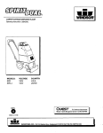
®
Operating Instructions (ENG)
MODEL:
WAV
10125050
Power Source: 115V Electric
Beginning with Serial No. 1000039213
Read instructions before operating the machine.
86038510-Y 01/10/09
PRV NO. 98780
MACHINE DATA LOG/OVERVIEW
MODEL _______________________________________
DATE OF PURCHASE __________________________
SERIAL NUMBER ______________________________
SALES REPRESENTATIVE # _____________________
DEALER NAME ________________________________
OPERATIONS GUIDE NUMBER ___________________
PUBLISHED __________________________________________
Copyright 1995 Windsor Industries, Printed in USA
YOUR DEALER
Name: __________________________________________________________________________________________________
Address: _______________________________________________________________________________________________
For the name and address of your dealer contact: Windsor Industries
Phone Number: _________________________________________________________________________________________
1
WAV 86038510 05/15/07
TABLE OF CONTENTS
Machine Data Log/Overview.........................1
Table of Contents..........................................2
HOW TO USE THIS MANUAL
How to use this Manual.................................1-1
SAFETY
Important Safety Instructions ........................2-1
Hazard Intensity Level. .................................2-2
Grounding Instructions..................................2-3
OPERATIONS
Controls.........................................................3-1
Machine Operation........................................3-2
Set Up ........................................................3-2
Operation. ..................................................3-2
Cleaning.....................................................3-2
MAINTENANCE
Belt/Brush Access.........................................4-1
Vac Motor Access & Filters...........................4-1
Vac Motor Brush Removal. ...........................4-1
Brush Motor. .................................................4-1
Carbon Brush................................................4-1
Daily Maintenance. .......................................4-2
Regular/Periodic Maintenance......................4-2
Wiring Diagram. ............................................4-3
Service Schedule. .........................................4-4
GROUP PARTS LIST
Brush and Drive Group. ................................5-1
Brush Height and Wheel Group. ...................5-3
Vacuum Group..............................................5-5
Handle Group................................................5-7
Lid/Decal Group. ...........................................5-9
Electrical Panel and Cover Group………….5-11
Suggested Spare Parts……………………...5-13
Warranty. .................................................... 5-14
WAV 86038510 05/15/07
2
HOW TO USE THIS MANUAL
This manual contains the following sections:
-
-
HOW TO USE THIS MANUAL
SAFETY
OPERATIONS
MAINTENANCE
PARTS LIST
The HOW TO USE THIS MANUAL section will tell
you how to find important information for ordering
correct repair parts.
Parts may be ordered from authorized Windsor
dealers. When placing an order for parts, the
machine model and machine serial number are
important. Refer to the MACHINE DATA box which
is filled out during the installation of your machine.
The MACHINE DATA box is located on the inside of
the front cover of this manual.
MODEL _____________________________________
The SAFETY section contains important information
regarding hazard or unsafe practices of the
machine. Levels of hazards is identified that could
result in product or personal injury, or severe injury
resulting in death.
The OPERATIONS section is to familiarize the
operator with the operation and function of the
machine.
The MAINTENANCE section contains preventive
maintenance to keep the machine and its
components in good working condition. They are
listed in this general order:
-
Belt/Brush Motor
Vac Motor and Filters
Vac Motor Carbon Brushes
Brush Motor
Carbon Brush
Daily Maintenance
Regular/Periodic Maintenance
DATE OF PURCHASE ________________________
The PARTS LIST section contains assembled parts
illustrations and corresponding parts list. The parts
lists include a number of columns of information:
SERIAL NUMBER ____________________________
SALES REPRESENTATIVE # ___________________
DEALER NAME ______________________________
OPERATIONS GUIDE NUMBER __________________
-
PUBLISHED ________________________________
-
Copyright 1995 Windsor Industries, Printed in USA
The model and serial number of your machine is on
the bottom back-end of the machine.
-
-
REF – column refers to the reference
number on the parts illustration.
PART NO. – column lists the part
number for the part.
PRV NO. – reference number.
QTY – column lists the quantity of the
part used in that area of the machine.
DESCRIPTION – column is a brief
description of the part.
SERIAL NO. FROM – column indicates
the first machine the part number is
applicable to. When the machine design
has changed, this column will indicate
serial number of applicable machine.
The main illustration shows the most
current design of the machine. The
boxed illustrations show older designs. If
column has an asterisk (*), call
manufacturer for serial number.
NOTES – column for information not
noted by the other columns.
NOTE: If a service or option kit is installed on your
machine, be sure to keep the KIT INSTRUCTIONS
which came with the kit. It contains replacement
parts numbers needed for ordering future parts.
1-1
WAV 86038510 05/15/07
IMPORTANT SAFETY INSTRUCTIONS
When using an electrical appliance, basic precaution
must always be followed, including the following:
READ ALL INSTRUCTIONS BEFORE USING THIS MACHINE.
! WARNING:
To reduce the risk of fire, electric shock, or injury:
Use only indoors. Do not use outdoors or expose to rain.
Use only as described in this manual. Use only manufacturer’s recommended components and attachments.
If the machine is not working properly, has been dropped, damaged, left outdoors, or dropped into water, return
it to an authorized service center.
Do not operate the machine with any openings blocked. Keep openings free of debris that may reduce airflow.
This machine is not suitable for picking up hazardous dust.
Machine can cause a fire when operating near flammable vapors or materials. Do not operate this machine near
flammable fluids, dust or vapors.
This machine is suitable for commercial use, for example in hotels, schools, hospitals, factories, shops
and offices for more than normal housekeeping purposes.
Maintenance and repairs must be done by qualified personnel.
During operation, attention shall be paid to other persons, especially children.
When leaving unattended, secure against unintentional movement.
The machine shall only be operated by instructed and authorized persons.
When leaving unattended, switch off or lock the main power switch to prevent unauthorized use.
Do not handle the plug or machine with wet hands.
Do not unplug machine by pulling on cord. To unplug, grasp the plug, not the cord.
Do not use with damaged cord or plug. Follow all instructions in this manual concerning grounding the machine.
Do not pull or carry by cord, use cord as a handle, close a door on cord, or pull cord around sharp edges or
corners.
Do not pull/run machine over cord. Keep cord away from heated surfaces.
Connect to a properly grounded outlet. See Grounding Instructions.
SAVE THESE INSTRUCTIONS
WAV 86038510 05/15/07
2-1
HAZARD INTENSITY LEVEL
The following symbols are used throughout this guide as indicated in their descriptions:
HAZARD INTENSITY LEVEL
There are three levels of hazard intensity identified by signal words -WARNING and CAUTION and FOR
SAFETY. The level of hazard intensity is determined by the following definitions:
! WARNING
WARNING - Hazards or unsafe practices which COULD result in severe personal injury or death.
! CAUTION
CAUTION - Hazards or unsafe practices which could result in minor personal injury or product or property
damage.
FOR SAFETY: To Identify actions which must be followed for safe operation of equipment.
Report machine damage or faulty operation immediately. Do not use the machine if it is not in proper
operating condition. Following is information that signals some potentially dangerous conditions to the
operator or the equipment. Read this information carefully. Know when these conditions can exist. Locate
all safety devices on the machine. Please take the necessary steps to train the machine operating
personnel.
FOR SAFETY:
DO NOT OPERATE MACHINE:
Unless Trained and Authorized.
Unless Operation Guide is Read and understood.
In Flammable or Explosive areas.
In areas with possible falling objects.
WHEN SERVICING MACHINE:
Avoid moving parts. Do not wear loose clothing; jackets, shirts, or sleeves when working on the
machine. Use Windsor approved replacement parts.
2-2
WAV 86038510 05/15/07
GROUNDING INSTRUCTIONS
THIS PRODUCT IS FOR COMMERCIAL USE
ONLY.
ELECTRICAL:
In the USA
this machine operates on a
standard 15 amp 115V, 60 hz, A.C. power
circuit . The amp, hertz, and voltage are listed
on the data label found on each machine.
Using voltages above or below those indicated
on the data label will cause serious damage to
the motors.
EXTENSION CORDS:
If an extension cord is used, the wire size must
be at least one size larger than the power cord
on the machine, and must be limited to 50 feet
(15.5m) in length.
GROUNDING INSTRUCTIONS:
This appliance must be grounded. If it should
malfunction or break down, grounding provides
a path of least resistance for electric current to
reduce the risk of electric shock. This
appliance is equipped with a cord having an
equipment-grounding conductor and grounding
plug. The plug must be inserted into an
appropriate outlet that is properly installed and
grounded in accordance with all local codes
and ordinances.
Improper connection of the equipmentgrounding conductor can result in a risk of
electric shock.
Check with a qualified
electrician or service person if you are in
doubt as to whether the outlet is properly
grounded. Do not modify the plug provided
with the appliance - if it will not fit the outlet,
have a proper outlet installed by a qualified
electrician.
This appliance is for use on a nominal 120-volt
circuit, and has a grounded plug that looks like
the plug in “Fig. A”. A temporary adaptor that
looks like the adaptor in “Fig . C” may be used
to connect this plug to a 2-pole receptacle as
shown in “Fig. B”, if a properly grounded outlet
is not available. The temporary adaptor should
be used only until a properly grounded outlet
(Fig. A) can be installed by a qualified
electrician. The green colored rigid ear, lug, or
wire extending from the adaptor must be
connected to a permanent ground such as a
properly grounded outlet box cover. Whenever
the adaptor is used, it must be held in place by
a metal screw.
WAV 86038510 05/15/07
2-3
CONTROLS
1
2
3
4
5
6
7
8
9
10
11
12
13
14
Main Handle. Adjusts for operator comfort and
storage.
Brush on/off lever. Activates brush when
depressed.
Accessory vacuum hose and wand. Allows
operator to clean edges, recessed, ledges,
upholstery, etc.
Detail tools Dusting brush, crevice and
upholstery tools for above the floor cleaning.
Dusting brush comes with adapter for
attachment directly to hose. Upholstery and
crevice tool connect directly to both the hose
and the wand. The crevice tool fits loosely on
the wand.
Handle Adjustment Lever. Located on the left
side of handle. Pull away from handle to loosen,
adjust handle and press parallel to handle to
Vac on/off switch. Turns on and off vac motor.
Brush motor circuit breaker. Provides
overcurrent protection for the brush motor.
Vac motor circuit breaker. Provides
overcurrent protection for the vacuum motors.
Exhaust filter. Filters exhaust air for safe and
quiet operation.
Accessory hose activation pedal. Press
pedal down to use the accessory hose. Lift up
with toe for normal use.
Brush adjustment lever. Allows operator to
adjust brush to proper height for the carpet. (1)
for low nap carpet, (5) for thick nap. Position (6)
is storage.
Dust bag cover. Raise to allow access to dust
bag and vac motors.
Cloth dust bag. High filtration cloth bag with
zipper opening to access paper bag.
Paper bag. Fits within cloth bag for clean and
easy dust removal.
3-1
WAV 86038510 05/15/07
7
8
OPERATIONS
WAVE SET UP
1. Take machine out of storage position by lowering
onto all four wheels.
2. Adjust handle to comfortable position at waist level
by opening adjustment lever on left side of
machine and moving handle. Lock back into
position by closing adjustment lever.
3. Install cloth filter bag inside the main body by
pushing the rubber collar over the chute.
FILTER/BAG COMPARTMENT
4. Unzip the cloth bag and place the paper bag
inside. Push the rubber gasket seal over the
chute. Zip cloth bag closed taking care not
to damage the paper bag and close lid.
5. Attach the detail tools to the top of the dust bag
cover by pressing the appropriate tool into the
clips.
6. Take the accessory wand and attach to the hose
and insert wand into the wand holster.
7. Strain relief.
NOTE: Attach strain relief/cord retainer to the
power cord.
1. Make a loop in power cord approximately
12” from receptacle end.
2. Slide cord loop through slot in retainer arm.
Pull slack cord back through slot to secure.
Attach retainer to handle.
WAV 86038510 05/15/07
3-2
OPERATION
HOW IT OPERATES
This machine is a portable, easy to use wide area
vacuum designed for use indoors, in a commercial or
light industrial environment.
When operating as a carpet vacuum, soil is lifted
from the carpet surface by a rotating brush and
carried into a removable bag by the vacuum motors.
1. Large debris such as paper cups, plates, etc.,
should be picked up before starting the cleaning
process.
2. Plan your cleaning route to work away from the
electrical source. Move machine forward at a
steady pace.
CLEANING
1. Adjust handle to comfortable position at waist
level or higher.
2. Use your finger to depress the Vacuum switch at
the base of the handle to activate the vacuum.
3. To adjust brush height, move the Brush
Adjustment lever on the right side to the correct
setting for the carpet being vacuumed. Lower
brush gradually until firm brush contact is heard.
BRUSH POSITION
! WARNING
KEEP MACHINE MOVING WHILE BRUSH ENGAGED.
DAMAGE TO CARPET COULD OCCUR IF NOT
MOVING.
NOTE: Always return brush to storage position after
using machine.
4. Depress the brush lever at the handle to start the
brush.
5. Move forward at a steady pace for through
cleaning. Run machine more slowly over
extremely soiled areas.
6. Use the right side of the machine for edge
cleaning.
7. To use the accessory wand and detail tools,
depress the foot lever in the back of the machine.
8. To keep the vacuum operating at maximum
efficiency, check the dust bag regularly. Empty
when 1/2 to 3/4 full. Always use with disposable
paper bag for best results.
9. When finished vacuuming, coil the cable by hand
by looping into about a 3 foot diameter, Hang
coiled cable over handle. Wrap the end around
the cable loop to secure.
10. Return brush to storage position.
3-3
WAV 86038510 05/15/07
MAINTENANCE
NOTE: THE FOLLOWING SERVICE ITEMS SHOULD BE PERFORMED BY
Vacuum Motor Carbon Brushes Replacement (Ametek)
AN AUTHORIZED SERVICE FACILITY OR AUTHORIZED SERVICE
PERSONNEL. ALL PARTS REFERRED TO IN THESE INSTRUCTIONS CAN
BE IDENTIFIED BY USING THE PARTS LISTS AND ILLUSTRATIONS ON THE
FOLLOWING PAGES.
End Cap
Carbon
Brushes
! WARNING
REMOVE MACHINE POWER CORD FROM ELECTRICAL
SOURCE BEFORE MAKING ANY REPAIRS OR
ADJUSTMENTS TO THE MACHINE.
TO ACCESS BELT/BRUSH MOTOR
1. Place machine in the upright storage position.
2. Remove (3) screws holding belt cover to chassis.
3. Loosen brush motor and roll belt off brush pulley.
4. Remove (5) screws holding brush housing to
chassis- (3) Located on front of housing,
(2) Located rear of housing.
5. Remove (2) screws from each end of brush housing
and remove brush assembly.
6. Inspect/replace brush and bearings as required. The
brush is equipped with a yellow wear indicator
bristles. The brush should be replaced when it wears
down to the height of the yellow bristles.
7. When installing belt push down on motor for proper
tension.
8. When reinstalling brush, check belt for proper
tension.
If armature commutator is grooved, extremely pitted or not
concentric, the motor will need to be replaced or sent to a qualified
service center.
Note:
Place
stop in
groove.
Important:
These brushes wear quicker as the length shortens due to
increased heat. Spring inside brush housing will damage motor if
brushes are allowed to wear away completely.
TO ACCESS AND REMOVE VAC MOTOR
AND FILTERS.
1.
2.
3/8 (9.5mm)
Open lid cover.
Remove (2) screws from each/both vac motor
brackets.
Vacuum Motor Carbon Brushes Replacement (Windsor)
End Cap
Carbon
Brushes
Periodically check the length of the carbon brushes. Replace both
carbon brushes when either is less than 3/8" (9.5mm) long.
!
W A R N IN G
THE GREEN GROUND WIRE MUST ATTACH THE MOTOR TO
THE POWER CORD FOR SAFE OPERATION. SEE THE
WIRING DIAGRAM.
NOTE: WHEN REPLACING ELECTRICAL COMPONENT
PARTS REFER TO WIRING DIAGRAM FOR PROPER
CONNECTION.
NOTE: THE VAC MOTOR IS PROTECTED BY A CIRCUIT
BREAKER LOCATED IN THE SWITCH PANEL. THE BREAKER
WILL ONLY TRIP UNDER CONDITIONS OF ABUSE.
If armature commutator is grooved, extremely pitted or not
concentric, the motor will need to be replaced or sent to a qualified
service center.
Important:
These brushes wear quicker as the length shortens due to
increased heat. Spring inside brush housing will damage motor if
brushes are allowed to wear away completely.
BRUSH MOTOR
1. Access belt and brush as described above.
2. Disconnect spring holding frame to brush motor
housing.
3. Remove (4) bolts holding motor housing to the
chassis and lift out motor asm.
4. Remove brush motor pulley and (2) bolts holding
motor to bracket, lift out brush motor.
CARBON BRUSH
1.
2.
Access belt and brush as described above.
Remove brush caps. NOTE: BRUSHES SHOULD BE
REPLACED WHEN WORN TO 3/8” OR LESS.
NOTE: BEFORE REINSTALLING BRUSH MOTOR BRACKET
ASSEMBLY IT’S RECOMMENDED THAT THE REAR SPRING
BE RECONNECTED TO THE FLAPPER ASSEMBLY.
3 [9.5mm]
8
Periodically check the length of the carbon brushes. Replace both
carbon brushes when either is less than 3/8" (9.5mm) long.
NOTE: PART NO. 86001250 – PRV NO. 140212 IF YOU HAVE
A MOTOR MARKED “LEESON.” PART NO. 86135360 – PRV
NO. 14340 IF YOU HAVE A MOTOR MARKED “86247470 – PRV
NO. 53617.”
WAV 86038510 05/15/07
4-1
MAINTENANCE
DAILY MAINTENANCE
1.
Shake down bag daily.
2.
Check power cord for damaged or frayed
insulation.
3.
Return brush adjustment lever to “STORE”
position when the machine is not in use.
4.
Check for and remove any lint or debris
around brush and brush housing.
REGULAR/PERIODIC MAINTENANCE
1.
Every 4 to 6 months remove wheels, clean axles,
and apply a thin coat of silicone lubricant to axles.
2.
The filter bag can be washed twice before losing
the filtering capability. This should be done using
a mild detergent in cool water and hung up to
drip-dry.
3.
Inspect and clean vac motor filters.
4.
Periodically inspect all hoses, electrical cables, filters,
gaskets and connections on your machine. Frayed or
cracked hoses should be repaired or replaced to
eliminate vacuum loss.
5.
The electrical cable must be well insulated, if the
cable insulation is broken or frayed, repair or
replace it immediately. Don’t take chances with
electrical fire or shock.
4-2
WAV 86038510 05/15/07
WIRING DIAGRAM
86266500
PRV76070
NO. 76070
86267220
PRV
NO. 880249
880249
BLK
VAC
MOTOR
BLK
88220
86268240
PRV NO. 88220
WHT
VAC
MOTOR
86268240
PRV NO. 88220
88220
WHT
RED
86010840
PRV
NO. 880118
880118
MAIN
SWITCH
BLK
BRUSH
MOTOR
MOLEX
86261560
880250
PRV
NO. 880250
RED
BLK
BLK
880248
86267210
PRV NO. 880248
86267200
PRV880247
NO. 880247
86267190
PRV NO.880246
880246
86005700
PRV57104
NO. 57104
880247
86267200
PRV NO. 880247
WHT
86266450
PRV NO. 76149
BLK
76149
BRUSH
86005700
PRV NO.
57104
57104
VAC
3 AMP
C.B.
13 AMP
C.B.
GRN
BLK
WHT
GROUND
POST
BLK
POWER
CORD
GRN
86006500
70024
PRV NO. 70024
880253
86261570
PRV NO. 880253
86261570
88349
PRV
NO. 88349
EXHAUST
SCREEN
WAV 86038510 05/15/07
SWITCH BOX
SCREW
MICRO
SWITCH
86006810
PRV NO. 70363
87016
86010640
PRV NO. 87016
86268300
PRV NO. 88231
BLK
70363
88231
HANDLE
4-3
MAINTENANCE
SERVICE SCHEDULE
MAINTENANCE
Check bag and replace if necessary
Check filters and replace if necessary
Check hoses for wear, blockages, or
damage
Inspect base for clogs
Check swivel neck for clogs; remove
clogs with fingers (if appropriate)
Check major gaskets for leakage
Check brush-should be clean with no
lint or strings attached
Wind cord and store in upright position
Check hoses for cracks or holes
Check all cords and handles for
damage or cracks; replace as
necessary
Check brushes for wear; replace if
necessary
Check brush strip for wear; replace if
necessary
Inspect and replace all filters including
exhaust, intake, and microfilters
Inspect, clean, and repair power head
– including brush housing
Check all bearings for fiber build-up
and noise
Check all gaskets for wear and leakage
Check belts for wear; replace if
necessary
Check vac motor carbon brushes
Check for arcing and pitting on any
electrical contacts; replace if found
Inspect and clean vac shoe; check for
dents and damage which would
detrimentally effect vacuum and brush
movement
Check overall performance of machine
4-4
DAILY
WEEKLY
MONTHLY
QUARTERLY
*
*
*
*
*
*
*
*
WAV 86038510 05/15/07
*
*
*
*
*
*
*
*
*
*
*
*
*
THIS PAGE LEFT BLANK INTENTIONALLY
WAV 86038510 05/15/07
4-5
BRUSH AND DRIVE GROUP
16
BRUSH ASSEMBLY
-DETAIL-
15
Vacuum Door Assembly
25
43
42
41
38
12
7
26
11
4
9
27
44
40
6
36
12
39
30
22
3
37
2
28
5
38
18
35
29
BRUSH ASSEMBLY
34
20
BRUSH DRIVE
MOTOR ASSEMBLY
21
22
19
21
10
VACUUM DOOR
ASSEMBLY
23
46
18
24 A,B
BRUSH
SET
33
1
8
18
14
33
22
21
45
17
31
32
BRUSH DRIVE
MOTOR ASSEMBLY
5-1
13
WAV 86038510 04/08/08
BRUSH AND DRIVE GROUP PARTS LIST
1
2
3
4
5
6
7
8
9
PART
NO.
86031700
86011010
86229050
86008210
86000900
86001130
86000740
86026100
86006510
PRV
NO.
14384
89199
14342
73998
09019
12039
03112
53623
70043
10
86005710
57105
1
11
12
13
14
15
16
17
18
19
20
21
22
23
86004080
86007060
86250420
86081840
86006040
86277930
86006550
86006600
86276700
86275570
86010660
86010740
86010840
36197
70710
64022
62841
64104
70119
70074
70114
70716
70505
87025
87090
880118
2
4
1
1
1
2
2
6
5
4
11
8
1
24A
86001250
140212
1
24B
86135360
14340
1
25
26
27
28
29
30
31
32
33
34
35
36
37
38
39
40
41
42
86087030
86010640
86000680
86001090
86198530
86276040
86008200
86005860
86080950
86004270
86002380
86006300
86002810
86010680
86006280
86005060
86003380
86270910
73992
87016
70361
11041
99809
70586
73996
57273
62650
39480
20046
66329
27063
87030
66281
51277
29202
57042
1
4
4
1
3.42'
2
1
1
2
1
1
1
1
2
1
1
1
1
43
86007690
73240
1
44
86305040
-
-
GASKET, FLAPPER WAV
45
46
86274750
86133710
70270
99862
2
6”
SCR, 1/4-20 X 3/4 HHCS
TAPE, 5/8W X 1/4T PORON 4701-01
REF
QTY
1
1
2
2
2
1
1
1
2
DESCRIPTION
SERIAL NO.
FROM
NOTES:
BODY, WAV
WELDMENT, HOSE CONNECT
BEARING BLOCK
SPACER, .75OD X .5ID X .5L
BEARING, 1.125OD X .50ID X .375
BRUSH
AXLE, .5OD X 29.94L
MOTOR ASM, BRUSH DRIVE
SCR, 10-32 X 5/8 PFHMS
NUT, 1/4-20 HEX W/ STAR
WASHER
GUARD, THREAD
SCR, 8-18 X 1/2 PFHST H-L
PULLEY, POLY V-BELT MOTOR
PLATE, MOTOR MOUNTING
PULLEY, BRUSH
SET SCR, 1/4-20 X 3/8
SET SCR, 10-32 X 1/4 KCP
SCR, #10 X 3/4 POLYFAST
SCR, 1/4-20 X 1/2 PPHMS PLTD
SCR, 1/4-20 X 1.0 HHCS PLTD.
WASHER, 1/4 LCK EXT STAR SS
WASHER, 1/4ID X 3/4OD
WIRE ASM, BRUSH MOTOR
BRUSH SET, LEESON BRUSH
MOTOR
BRUSH SET, WINDSOR BRUSH
MTR
SHOE, VAC
WASHER, #10 LOCK EXT STAR SS
SCR, 10-32 X 1/2 PHTR PLTD
BELT, 220 J-6 POLY-V
FOAM TAPE, 1/8T X 3/4 1SDA
SCR, 1/4-20 X 3/4 BLK PPHTC
SPACER, .50OD X .37ID X .44L SS
NUT, 1/4-20 X 12MM HEX BARREL
PLATE, VAC HOSE RETAINER
HOSE ASM, 1.5 X 30.0 BLK VAC
CLAMP, 2.25" WORM GEAR
PLATE, ACCESS
COLLAR, 3/8 SHAFT
WASHER, 3/8ID X 3/4OD X 1.25
PEDAL, WAND ACTIVATOR
LINKAGE, WAND ACTIVATOR
DOOR, WAV FLAPPER
NUT, 3/8 PUSHLOCK
SPRING, EXT. 0.5OD X 2.25L X
.063W
WAV 86038510 10/23/08
10125050000424
WAS
86003900
5-2
BRUSH HEIGHT AND WHEEL GROUP
MAIN FRAME ASSEMBLY
4
8
14
6
22
10
20
20
24
21
23 21
24
24
19
19
16
3
12
9
2
7 17
5
1
19
11
15
18
13
5-3
WAV 86038510 07/24/07
BRUSH HEIGHT AND WHEEL GROUP PARTS LIST
REF
1
2
3
4
5
6
7
8
9
10
11
12
13
14
15
16
17
18
19
20
21
22
23
24
PART
NO.
86005860
86008200
86006660
86008750
86001170
86279290
86001220
86091480
86092030
86010910
86259960
86010790
86001660
86270880
86005680
86080800
86279420
86000390
86010740
86010730
86010660
86007740
86006920
86275570
PRV
NO.
57273
73996
70190
80673
140054
89131
140177
14351
14353
89094
89506
87163
41236
57032
57047
62623
87156
67376
87090
87088
87025
73362
70507
70505
QTY
1
1
1
1
1
1
1
1
1
2
2
1
2
2
4
1
2
1
8
3
4
1
1
8
DESCRIPTION
NUT, 1/4-20 X 12MM HEX BARREL
SPACER, .50OD X .37ID X .44L SS
SCR, 1/4-20 X 1/2 BHCS DL
KNOB, WITH 1/2-13 F-INSERT
BUSHING, BRZ 3/8-16 X .74 X .50
WELDMENT, FRAME
BRACKET, AXLE HANGER
BAR, HEIGHT ADJUSTMENT
BRKT, HEIGHT ADJ RIGHT
WHEEL, 1-5/8D CUSHION
WHEEL, 1 15/16” x 10” HOOSIER
WASHER, 3/8 SPLIT LOCK PLTD.
HUBCAP, 5/8" SHAFT
NUT, 3/8-16 SERRATED FLG.
NUT, 1/4-20 NYLOCK PLTD.
PLATE, AXLE MOUNTING
WASHER, .75ID X 1.25OD X .125
ROD, .625 X 25.30 CRS
WASHER, 1/4ID X 3/4OD
WASHER, 3/4ID X 1.00 PLTD.
WASHER, 1/4 LOCK EXT. STAR SS
SPRING, EXT .5OD X 1.75L X .06W
SCR, 3/8-16 X 3/4 HHCS GR5 PLTD.
SCR, 1/4-20 X 1.0 HHCS PLTD.
WAV 86038510 07/24/07
SERIAL NO.
FROM
1012505000207
NOTES:
WAS 89279
5-4
VACUUM GROUP
5
6
14
13
4
9
10
17
7A, 7B (BRUSH SET)
15
3
8
16
11
12
2
1
5-5
WAV 86038510 05/15/07
VACUUM GROUP PARTS LIST
REF
PART NO.
PRV NO.
QTY
DESCRIPTION
1
2
3
4
5
6
86276040
86064180
86010650
86068760
86215090
86001200
70586
36185
87018
140196
140949
140164
5
1
4
2
2
1
SCR, 1/4-20 X 3/4 BLK PPHTC
GUARD, BELT
WASHER, #10 X 9/16 OD
BRKT, VAC MOTOR MOUNTING
BAG, PAPER WIDE AREA VAC
BAG, CLOTH U19855
7A
86135260
140211
-
BRUSH SET, VAC MOTOR
7B
86135320
140687
-
BRUSH SET, 120V VAC WINDSOR
8
9
10
11
12
13
14
15
16
17
86006770
86003510
86086800
86237580
86006820
86010660
86275570
86006600
86062690
86026850
70323
34012
73461
35204
35200
87025
70505
70114
29205
53783
2
2
2
2
1
2
2
4
1
2
SCR, 10-32 X 1/4 PHTR PLTD.
FILTER, VAC MOTOR
SCREEN, 5/32 .032T 20GA AL 3X3
GASKET, 4.0ID X 5.5OD X .38THK PRN
GASKET, FILTER BAG NECK
WASHER, 1/4 LOCK EXT STAR SS
SCR, 1/4-20 X 1.0 HHCS PLTD.
SCR, #10 X 3/4 POLYFAST
DEBRIS CHUTE, WAV
VAC MOTOR, 120V 5.7 1ST
WAV 86038510 05/15/07
SERIAL NO.
FROM
*
NOTES:
SERVICE
ONLY
SERVICE
ONLY
5-6
HANDLE GROUP
34
27
25
23
4
31
29
33
5
3
37
24
21
32
HANDLE ASSEMBLY - DETAIL 9
27
19
22
2
14
20
11
HANDLE ASSEMBLY
7
28
35
36
28
27
6
1
16
18
10
15
12
8
13
26
17
30
5-7
WAV 86038510 05/15/07
HANDLE GROUP PARTS LIST
REF
PART NO.
PRV NO.
QTY
1
2
3
4
5
6
7
8
9
10
11
12
13
14
15
16
17
18
19
20
21
22
23
24
25
26
27
28
29
30
31
32
33
34
35
36
37
86274640
86076510
86268300
86091470
86069190
86198480
86004490
86246320
86238290
86005630
86005710
86008650
86272300
86005020
86006380
86256170
86005050
86010710
86271240
86007050
86006720
86006800
86007100
86007820
86255250
86089370
86010640
86010650
86010690
86006510
86271280
86249500
86146430
86006810
86007010
86010660
86279220
70253
38272
88231
140309
140310
27371
41373
51142
36104
57022
57105
80604
66133
51184
67374
73169
51254
87080
57154
70683
70245
70361
72093
73698
73843
78365
87016
87018
87068
70043
57163
62839
51299
70363
70663
87025
57104
1
1
1
1
1
4
1
1
2
1
1
1
1
2
1
1
2
2
2
4
2
2
1
2
1
1
5
6
4
4
2
1
1
1
1
1
1
DESCRIPTION
SERIAL NO.
FROM
NOTES:
SCR, 10-32 X 1.25 PPHMS
HANDLE, MAIN
WIRE, 6" GRN/18 76008 X 76011
BAR ASM, BRUSH SWITCH
BRKT, SWITCH MOUNTING
CLIP, POWER CORD
HOLSTER, WAV WAND
LEVER, HANDLE LOCK
GRIP, HANDLE ADJUSTMENT
NUT, 3/8-16 THIN NYLOCK SS
NUT, 1/4-20 HEX W/ STAR WASHER
RING, RUE COLLAR 1/4 PLTD.
PIN, CLEVIS 3/16 X 7/8L
LOCK, HANDLE ADJUSTMENT
ROD, HANDLE ADJ.
STRAIN RELIEF, CORD HOOK
LOCK, HANDLE
WASHER, .5 X 1.25 FLAT PLTD.
NUT, CAP 1/4 DIA RETAINING PLTD.
SCR, 10-32 X 3/8 PHMS SS DL
SCR, 4-40 X 3/4 PHMS PLTD.
SCR, 10-32 X 1/2 PHTR PLTD.
SWITCH, 125VDC SPST N.O.
SPACER, .50D X .28ID X .38L
SPRING, TORSION
TUBE, HANDLE ADJUSTMENT
WASHER, #10 LOCK EXT. STAR SS
WASHER, #10 X 9/16OD
WASHER, 1/8 RIVET BACKUP
SCR, 10-32 X 5/8 PFHMS SS
NUT, 4-40 W/ STAR WASHER
PLATE, SWITCH BOX INSLTR
LEVER, SPRING STEEL
SCR, 10-32 X 3/8 PHTR PLTD.
SCR, 1/4-20 X 3-1/4 HHCS PLTD.
WASHER, 1/4 LOCK EXT STAR SS
NUT, 10-32 W/ STAR WASHER PLTD
WAV 86038510 01/10/09
5-8
LID/DECAL GROUP
18
17
16
14
15
13
4
7
6
12
3
2
1
10
5
11
8,9
5-9
WAV 86038510 05/15/07
LID/DECAL GROUP PARTS LIST
REF
PART NO.
PRV NO.
QTY
1
2
3
4
5
6
7
8
9
10
11
12
13
14
15
16
17
18
86003780
86234760
86006500
86031930
86237590
86255240
86006290
86245590
86245580
86246560
86245620
86245600
86000070
86274520
86002990
86283600
86000080
86000160
35171
27674
70024
51335
35207
73838
66285
50758
50757
50776
50762
50759
02083
70233
27744
02085
02084
02292
1
1
2
1
2
1
2
1
1
1
1
1
1
6
3
2
1
1
DESCRIPTION
SERIAL NO.
FROM
NOTES:
GASKET, ACCESSORY PORT
COVER, ACCESSORY PORT
SCR, #8 X 1/2 SHT METAL SS
LID, WAV
GASKET, FOAM 1/2 X 10
SPRING, .24OD X 2.0 COMP
PIN, .250 X .75 CRS
LABEL, WAVE LOGO RIGHT
LABEL, WAVE LOGO LEFT
LABEL, WARNING
LABEL, BRUSH HEIGHT ADJ.
LABEL, WINDSOR LOGO
BRUSH, 3" DUST
SCR, #10 X 3/8 PH HI-LO PLTD
CLIP, C 1-1/2 PLASTIC
BRUSH, UPHOLSTERY
TOOL, 5" UPHOLSTERY
TOOL, 11" PLASTIC CREVICE
WAV 86038510 05/15/07
5-10
ELECTRICAL PANEL AND COVER GROUP
18
1
NUT SUPPLIED
WITH SWITCH
5
6
4
7
NUTS SUPPLIED WITH
CIRCUIT BREAKER
2
3
4
10
12
11
15
19
16
13
14
17
5-11
WAV 86038510 05/15/07
ELECTRICAL PANEL & COVER GROUP PARTS LIST
REF
PART NO.
PRV NO.
QTY
1
2
3
4
5
6
7
8
9
10
11
12
13
14
15
16
17
18
19
86234300
86279220
86261560
86005670
86261570
86230120
86005680
86003550
86082750
86238400
86086830
86006500
86236080
86063720
86172770
86230050
86245040
23672
87104
880250
57040
880253
14313
57047
OPEN
OPEN
34310
66323
36125
73863
70024
34326
27738
70610
140239
50279
1
1
1
2
1
1
2
1
1
1
1
8
1
1
1
1
1
DESCRIPTION
SERIAL NO.
FROM
NOTES:
CORD ASM, 115V
WASHER, 1/2 EXT. STAR
WIRE ASM, MAIN SWITCH/BREAKER
NUT, 1/2 NPT CONDUIT
WIRE ASM, BRUSH/HANDLE SWITCH
BREAKER, 13A CIRCUIT
NUT, 1/4-20 HEX NYLOCK
FOAM, SOUND INSULATION
PLATE, ELECTRICAL PANEL
GROMMET, 3/4ID X 1.38OD
SCREEN, EXHAUST
SCR, #8 X 1/2 SHT METAL SS
FILTER, EXHAUST
COVER, REAR
SCR, 1/4-20 X 1.0 BLK THUMB
BREAKER, 3.0A THERMAL CIR.
LABEL, GROUND SYMBOL
WAV 86038510 05/15/07
5-12
SUGGESTED SPARE PARTS
PART NO.
PRV NO.
86001090
86215090
86003510
86236040
86001200
86135260
86001250
86135360
11041
140949
34012
34309
140164
140211
140212
14340
5-13
SERIAL NO.
FROM
DESCRIPTION
BELT, 220 J-6 POLY-V
BAGS, PAPER (PKG. OF 10)
FILTER, VAC MOTOR
FILTER, EXHAUST
BAG, CLOTH
BRUSH SET, VAC MOTOR
BRUSH SET, 90 VDC 1/4HP MOTOR
BRUSH SET, 53616/53617
WAV 86038510 05/15/07
NOTES: