1
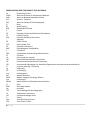
A Thinker’s Guide for Electrical Leakage Testing of Ultrasound Probes James Gessert, B.Sc., BSEE G. Wayne Moore, B.Sc., MA, FASE Acertara Acoustic Laboratories Correspondence: G. Wayne Moore 1|Page 1860 Lefthand Circle, Suite H, Longmont, CO 80501 USA E-mail: [email protected] www.acertaralabs.com Acertara Acoustic Laboratories Correspondence: G. Wayne Moore 1860 Lefthand Circle, Suite H, Longmont, CO 80501, USA Email: [email protected] www.acertaralabs.com PREFACE This text is designed to provide the reader with sufficient knowledge of the principles of electrical leakage testing as it relates to diagnostic ultrasound probes; to serve as a basis for understanding the “why and how” such testing is required and performed in the clinical setting. A secondary objective is to provide sufficient references from various stake-holders in this testing, (e.g., regulatory, standards, clinical, manufacturing, etc.), to enable you to read and understand, contextually, the various requirements, methodologies, and vernacular associated with the text in these references. This White Paper is structured to help the reader learn. Basic principles are mentioned early in the text and then are repeated and expanded upon, and integrated into later sections. Our research for this paper revealed a good deal of confusion and “open for interpretation” requirements within the various stakeholder documents. We strongly urge the reader to look carefully at ultrasound user manuals for specific instructions related to probe electrical leakage testing and ensure those instructions are compatible with standards and regulatory requirements. Any variances from these requirements or ambiguous language found in User Manuals should be brought to the attention of the OEM, and clarification sought. In this paper we have highlighted, or noted in red, certain key concepts, warning of things to look out for (we label: NOTE BENE) or items to pay special attention to in any additional future reading you may do. The information presented in this White Paper, while greatly simplified, is accurate to the maximum possible degree. Finally, a brief philosophical thought. Medical imaging devices are some of the most brilliantly conceived systems ever developed. They provide insights into disease processes providing the ability to diagnose much earlier making treatments significantly more effective. But these systems must also be properly maintained, and this relates to the safety of the device, both for the patient as well as the user. Acertara Acoustic Laboratories has dedicated itself to creating technologies that allow an HTM (Healthcare Technology Manager) and other technical personnel to validate the safe performance of these products. We sincerely hope that you will share this commitment of always putting the patient first. 1|Page INDEX Page Definitions 3 Warning Labels 5 Abbreviations Used Throughout this Document 6 General Discussion about Ultrasound Probes 7 Visual and Tactical Inspection 11 Probe Labeling 12 Why Measure Electrical Leakage in Probes? 17 Ultrasound Laboratory Accreditation 22 Measuring Devices and Background 23 Components Used in Testing 24 Electrical Leakage Testing Process 25 Manufacturer’s Recommendations 27 Samples of Probe Failures to Look for 28 Conclusion 29 References 30 About Acertara and the Authors 31 2|Page DEFINITIONS: Additive Current Leakage: Leakage current is additive in the presence of multiple patient contact devices and must be accounted for when assessing patient electrical shock risk Applied Part: IEC 60601-1 uses the term “applied part” to refer to the part of the medical device which comes into physical contact with the patient in order for the device to carry out its intended function Class I: Equipment protection against electric shock by (earthed) additional protection to basic insulation through means of connecting exposed conductive parts to the protective Earth in the fixed wiring of the installation Conductivity: The ability of a solution to pass an electric current Defibrillation-Proof: An applied part that is protected against the effects of a discharge of a cardiac defibrillator to the patient Dielectric Strength: the maximum electric field that a pure material can withstand under ideal conditions without breaking down, i.e., without experiencing failure of its insulating properties. Electrical Safety: The status of protective measures within an equipment/system designed and produced in accordance with IEC 60601-1 that limit the effects of electrical current on a patient, user or other individuals in accordance with this standard Electrical Leakage Current: The total current flowing from MAINS PARTS to earth via: a) the PROTECTIVE EARTH CONDUCTOR and ACCESSIBLE CONDUCTIVE PARTS of the enclosure and APPLIED PARTS (differential and alternative method), or b) the ACCESSIBLE CONDUCTIVE PARTS of the enclosure and APPLIED PARTS (direct method) Enclosure Leakage Current: Total current flowing from the enclosure and all accessible parts (excluding applied parts) through an external conductive connection other than the protective ground conductor to ground or another part of the enclosure Ground Leakage Current: Current flowing from all mains parts through or across the insulation into the protective ground conductor of the grounded power cord IEC: The International Electrotechnical Commission is a non-profit, non-governmental international standards organization that prepares and publishes International Standards for all electrical, electronic and related technologies; collectively known as "electrotechnology". The various published Standards use the format of IEC XXXXX-X, where X= a number, for example – IEC 60601-1 Leakage Test: Tests designed to simulate a human body coming in contact with different parts of the equipment. The measured leakage current values are compared with acceptable limits Maintenance: Involves the combination of all technical and administrative means, including supervisory ones, to keep Medical Electrical (ME) Equipment or an ME System in a normal working condition or restored to normal working condition Patient: A living being (person or animal) undergoing medical or dental investigation or treatment Patient Auxiliary Current: Current flowing in the patient in normal use between parts of the applied part and not intended to produce a physiological effect, for example, bias current of an amplifier, current used in impedance plethysmography 3|Page Patient Leakage Current: Current flowing from the applied part via the patient to earth or flowing from the patient via an F-Type applied part to earth originating from the unintended appearance of a voltage from an external source on the patient Recurrent Test: Testing conducted, at a defined time interval, for the assessment of safety Reinforced Insulation: A single system of insulation that provides two levels of protection against electrical shock Repair: Restoring to a safe, functional, and normal condition Servicing: The combination of all means for maintaining the ME Equipment or ME System within the specified requirements of the Manufacturer Service Life: The expected service life of a probe is defined by each manufacturer and is arrived at by considering a number that includes anticipated use as well as several manufacturing variables. Most manuals spell out the Caveat to the expected service life such as; “The expected service life is X years if the specified maintenance and inspection procedures are performed.” Single Fault Condition: condition of ME EQUIPMENT in which a single means for reducing a risk is defective or a single abnormal condition is present Standard: A standard is a document that provides requirements, specifications, guidelines or characteristics that can be used consistently to ensure that materials, products, processes and services are fit for their purpose. Supplemental Insulation: Independent insulation applied in addition to basic insulation in order to provide protection against electrical shock in the event of a failure of basic insulation TEE: Transesophageal echocardiography, an ultrasound examination where the probe is introduced into the patient’s esophagus Ventricular Fibrillation: a heart rhythm problem that occurs when the heart beats with rapid, erratic electrical impulses. This causes pumping chambers in the heart (the ventricles) to quiver uselessly, instead of pumping blood. During ventricular fibrillation, blood pressure plummets, cutting off blood supply to vital organs and can be a fatal occurrence 4|Page VARIOUS PROBE WARNING LABELS FROM ULTRASOUND OEM USER MANUALS All intraoperative studies must be performed with a Type CF classified transducer All TEE transducers are designed to be defibrillator safe in accordance with IEC 60601-1. Nevertheless, always remove the transducer from the patient before defibrillation. WARNING: Only use Type BF transducers with the ultrasound system to maintain a level of protection against electrical shock. WARNING: When using an endocavity or intraoperative transducer with a TYPE CF applied part, the patient leakage currents may be additive. WARNING: The leakage current test for transesophageal transducers must be done prior to each use in order to reduce the likelihood of harm to the patient. Refer to the manufacturer’s instructions included with the tester. WARNING: Transducer abnormalities may cause electrical shock or injury to the patient. Caution: Do not bend the flexible shaft into a curve of less than 30.5cm in diameter. Caveat on Warning Labels: Some warning label language may be ambiguous, or may not cite a reference directly or correctly. An example is found in the second warning above that uses the terminology “defibrillator safe”, a term not used or defined in the ISO Standards. If you suspect this is the case, you should contact the manufacturer for a more detailed explanation and the reference(s) they are citing. 5|Page ABBREVATIONS USED THROUGHOUT THIS DOCUMENT AC Alternating Current AIUM American Institute of Ultrasound in Medicine ANSI American National Standards Institute A/P Anterior - Posterior ASE American Society of Echocardiography B Body BF Body Floating BNS Bending Neck Sheath C Celsius CE European Conformity (Conformité Européene) CF Cardiac Floating CSA Canadian Standards Association ° Degree(s) DC Direct Current DUT Device Under Test EC European Community EMC Electromagnetic Compatibility F Fahrenheit FDA United States Food and Drug Administration FS Full Scale Hz Hertz (cycle-per-second) IAC Intersocietal Accreditation Commission IEC International Electrotechnical Commission ISO International Organization for Standards (Organisation internationale de normalisation) IT Insertion tube (e.g., TEE probe) kg kilogram(s) µA microamp(s) mA milliampere(s) ME Medical Electrical MITA Medical Imaging Technology Alliance mm millimeter(s) NEMA National Electrical Manufacturers Association Ω Ohm RMS Root Mean Square sec second(s) TEE Transesophageal Echocardiography UL Underwriters Laboratory ULT Ultrasound Leakage Tester V Volt(s) VAC Volts Alternating Current VDC Volts Direct Current 6|Page GENERAL DISCUSSION ABOUT ULTRASOUND PROBE COMPONENTS AND CONSTRUCTION This section contains a very high-level discussion on ultrasound probes. For the reader who would like to delve in deeper in understanding this technology, additional detailed information can be obtained by contacting us at Acertara and requesting our published paper entitled, “The Silent Revolution – Catching Up With the Contemporary Composite Transducer”. Understanding the basic construction of an array can yield insight into, and provide context for, understanding why the various probe testing devices, including electrical leakage testers, are designed the way they are and provide the kind of information they do. Currently available real-time diagnostic ultrasound systems and the transducers associated with them can be divided into three main categories: (1) linear sequenced arrays, e.g., linear and curved linear, (2) phased arrays, e.g., 1D, 1.5D, and 2D matrix, and (3) mechanical sector, normally a single element probe that is mechanically steered. The most commonly used probes today are from categories 1 and 2. To establish common terms for the various parts of a probe, please see the diagrams on Page 8. A modern electronic array ultrasound probe normally consists of the following major components: 1) An acoustic stack, comprised of: a) Lens b) Matching layers c) Array d) Backing material 2) An ergonomically designed housing matching the form, fit and intended function of the probe 3) Cable termination within the probe housing (see Photo on Page 10) 4) A cable with multiple co-axial wires connecting the probe housing to the probe connector 5) A probe connector normally having one or more of the following inside the connector: a) Multiplexer circuit b) Tuning circuit c) Cable Termination board In addition to the above, a number of modern ultrasound probes have dedicated electronics integrated into the probe housing as part of the acoustic stack, for example the X7-2t TEE probe by Philips (see photo below) Array Electronics Array X7-2t 7|Page STANDARD COMMON PROBE NOMENCLATURE 1 2 3 4 5 6 Transducer Lens Transducer Housing Transducer Strain Relief Cable Connector Strain Relief Connector Housing 1 6 2 5 4 3 STANDARD TEE PROBE NOMENCLATURE 2 4 1 2 3 4 5 6 7 Insertion Tube Cable Transducer Connector Transducer Control Housing Distal Tip (contains acoustic stack) Insertion tube sleeve Depth markers 5 3 6 7 8|Page 1 Acoustic Stack The heart of an ultrasound probe is the acoustic stack, the main component of which is the array. Composite arrays are composed of: 1) a Piezo-electric (PZ) material that provides the necessary transduction of mechanical to electrical energy and vice versa, and 2) a supporting polymer that isolates the element while shaping the mechanical and electrical properties of the PZ elements. It is the physical distribution of PZ and polymer that makes the array and specifies its behavior. The array construction following a specific design depends on the well-developed “dicing and filling” techniques used in today’s transducer manufacturing . Construction begins with a block of PZ material that is “diced” to form PZ elements held by a common spine (see Diagram below). The diced regions are then filled with polymer. The final configuration is obtained by lapping the array “front” and “back” to remove polymer on the face and the PZ spine on the back and to set the array center operating frequency. The distribution of PZ and polymer provides a specific pattern of connectivity and coupling. Dicing Slots Filled with Polymer & Lapped To PZ Material Spine is Lapped to The Polymer Fill Diced PZ Material Ready for Polymer Spine Holds The Array Together Connectivity refers to the continuity of each material along each of the three axes. Specific dicing and filling can produce an array that looks like a PZ-polymer sandwich (common to many current linear, convex, and phased arrays), or an array of PZ elements where each is surrounded by polymer (found in 1.5D and 2D Matrix arrays). Coupling refers to the ability to transfer ultrasound out of an array and into the tissues and the reverse when echoes return. Acoustic coupling improves when quarter-wave layers of material with intermediate acoustic impedance values are bonded to the array face. The lens attached to the array is the path to the patient. If the lens is compromised; an electrical pathway can be established from the probe into the patient. A sample of this is shown on Page 28, Photos 1 & 2. 9|Page Overall Probe Design Considerations Signal-to-noise performance is essential from the design of the probe as the probe must be relatively noise immune. This is required because modern composite arrays are very broadband, relative to frequency, and highly sensitive. Additionally, modern ultrasound systems have front-end electronic designs that are capable of >100dB dynamic range. What is key in the design is that receiver sensitivity is maximized and the noise generation and susceptibility be minimized. Electrical noise may be generated by the transducer itself, or it can enter into the ultrasound system as interference from outside sources. Immunity to interference is usually accomplished by using coax cables to carry signals between the transducer and the system, additional shielding in and around the acoustic stack (see Photos below), and in newer arrays, placing the pre-amp and micro-beamforming electronics near to, or integrated in the acoustic stack design. Array Shielding Flex Circuit Connection to Array Cable Termination Although the focus of this paper is on electrical leakage testing, it is noted here that one of the more common complaints associated with probe repair is noise in the B-mode image, and especially in the various Doppler modes; pulse wave (PW), continuous wave (CW), and color flow (CF). One of the reasons for performing electrical leakage testing is to detect fluid ingress into a probe (see Page 28); this fluid ingress can also cause noise “sparkling” issues in all ultrasound modes of operation. When fluid ingress is detected early enough, a probe can normally be dried out and repaired, returning the probe to normal operation both from a safety standpoint, as well as from a clinical performance standpoint (i.e., eliminating the noise). Noise issues can also be caused by physical trauma and tears to the probe Cable Tear cable, specifically the co-axial wires within the cable, or to the ground shielding itself (see Photo to right). 10 | P a g e VISUAL AND TACTILE INSPECTION OF PROBES IN-SERVICE Because probes are fragile and used in sometimes difficult environments, all ultrasound probes should be thoroughly inspected prior to each use to look for any cracks, tears, holes, or any other structural damage. In each OEM probe user manual we reviewed, this visual inspection was stressed in its importance. Carefully inspect the connector, cable and the transducer housing. Special attention should be paid when inspecting TEE and Intraoperative probes. For detailed information on probe care, please request our White paper entitled “Common Ultrasound Probe Failures”. As a general guideline from all manufacturers the following is a minimum probe inspection recommendation. An inspection should be both visual and tactual; Acertara also recommends using a 10x Illuminated Loupe to closely inspect the insertion tube sleeve for any small holes (see Photo below). It should be noted that even when using a 10x loupe there may be fluid pathways allowing ingress too small to detect by visual acuity as in the example below; again underscoring the importance of electrical leakage testing. NOTE: If an obvious hole is detected in the protective covering do not perform a leakage test as fluid ingress may occur, resulting in probe damage. Before use, inspect the following areas of the transducer: Transducer body including the shaft, handle, & nose-piece: inspect for cracks, abrasions, or evidence of impact Acoustic lens or cap: check for cuts, tears, gouging, abrasion, swelling, bubbling, delamination or discoloration Strain relief and cable assembly: check for cracks, cuts, tears, abrasion, kinking or crushing System connector: check for foreign objects, broken latches, or bent pins and shielding. Cable assembly: check for discoloration or inflexibility of the transducer cable or strain-relief Transesophageal transducers (TEE): inspect the insertion tube for tears, rips, or discoloration; pay particular attention to the insertion tube sleeve (shown below) where bite marks may occur TEE Insertion Tube Sleeve 10x Loupe with Light 11 | P a g e Bite Marks: Is there a path for fluid? PROBE LABELING DEFINITIONS AND TECHNICAL BACKGROUND There are encapsulation requirements applicable to products with high reliability requirements and where the entry of dust could cause problems. IP-classification testing is carried out in accordance with the global IEC 60529:2000 standard. Labeling for ultrasound probes are normally shown on the probe connector as illustrated on the various examples of probe connectors on Page 13. IP stands for “International Protection), the other numbers and letter “x” are explained below. The symbol of the man icon or the heart icon in a box is explained on Page 14. NOTE: If the specified IPX classification is applicable for only part of the TRANSDUCER ASSEMBLY, the marking of the IPX code on the TRANSDUCER ASSEMBLY is not required. Degree of protection against water (Second Characteristic Numeral) IPx-1 The enclosure is exposed to dripping water, with a flow rate of 1 mm/min, for ten minutes. Acceptance for Class IPx-1 requires no water to have penetrated into the item in such a quantity, or in such a position, as to prevent satisfactory operation of the item or to present a safety risk IPx-7 As seen on Page 13, an example of this indicator is seen on the Toshiba probe. The number 7 in the label, IPx-7, means that ingress of water in quantities causing harmful effects shall be prevented when the enclosure is immersed in 1 meter of water for 30 minutes. This applies to the cable and probe housing only, not to the probe connector. The “x” means that there is no requirement for protection of ingress of solid foreign objects. First Characteristic Numeral IPx-8 This label indicates the probe’s degree of protection against ingress of fluid. The test is made by completely immersing the enclosure in water. Test conditions are subject to agreement between manufacturer and user. Acceptance for Class IPx-8 requires no water to have penetrated into the item in such a quantity, or in such a position, as to prevent satisfactory operation of the item or to present a safety risk. This protection applies to the endoscope portion of the TEE probe. Second Characteristic Numeral 12 | P a g e X 0 1 2 3 4 5 6 Protection against ingress of solid foreign objects Not required Non-protected ≥ 50mm diameter ≥ 12.5mm diameter ≥ 2.5mm diameter ≥ 1.0 mm diameter Dust-protected Dust-tight X 0 1 2 3 4 5 6 7 8 Protection against ingress of water with harmful effects Not required Non-protected Vertical dripping Dripping (15° tilted) Spraying Splashing Jetting Powerful jetting Temporary immersion Continuous immersion Various IPx Labels IPx-1, Philips X7-2t Note 1 IPx-7, Toshiba PVT-382BT IPx8, Siemens 17L5 Note 1 Although Philips labels the X7-2t probe as IPx-1 on the connector, its User Manual states that the insertion tube and tip are rated at IPx-7; this allows for submersion for cleaning/disinfecting and electrical leakage testing. Please see Note on preceding Page. IEC 62353 states: “Parts of the TRANSDUCER ASSEMBLIES specified by the MANUFACTURER as intended to be immersed during NORMAL USE, shall meet the requirements of watertight equipment (IPX7).” 13 | P a g e APPLIED PARTS CLASSIFICATIONS Applied parts are classified as Type B, Type BF, or Type CF, according to the nature of the device and the type of contact with a patient. Each classification has differing requirements from the point of view of protection against electrical shock. B: Is the least stringent classification, and is used for applied parts that are not functionally conductive and can be immediately released from the patient; for example, medical battery charges, ear examination equipment. Type B applied parts may be connected to earth, while Type BF and CF are “floating” and must be separated from earth. BF: Is less stringent than CF, and is generally for devices that have contact (intentional physical contact) with the patient, or have medium or long term contact with the patient. Examples additional to ultrasound include monitors and ventilators. BF Defibrillator-Proof: To obtain this label, additional testing is required of the manufacturer per IEC 60601-1 section 8.5.5.1 (page 77) – “Defibrillation protection”. The Defibrillation-Proof applied part marking indicates that the applied part can safely remain attached to a patient who is being defibrillated without any adverse effect on subsequent use of the Medical Electrical equipment. NOTE BENE: Although mentioned in some OEM User Manuals the term “Defibrillator Safe” does not appear, nor is it defined, in any Standard. If the probe you are using is referred to as defibrillator safe in the user manual, please contact your OEM and ask for a reference and definition for this term. CF: Is the most stringent classification, being required for those clinical applications where the applied part is in direct conductive contact with the heart (intentional cardiac physical contact) or other clinical applications as considered necessary. Examples additional to intraoperative ultrasound would include defibrillators and heart monitors. Type CF classification indicates that the degree of protection from electrical shock afforded by the transducer is suitable for all patient applications including direct cardiac and intraoperative applications. Although a TEE probe is inserted into the esophagus and images the heart, it does not come into physical contact with the heart, therefore it is classified as a BF device rather than CF. Type CF, as shown below, has the icon of a heart in a box. The label with the “man-figure” icon inside the rectangle (shown below) indicates a BF level device that is NOT protected for use with defibrillation. NOTE BENE: It is noted here that used probes purchased from non-OEM sources may not have all of the required labeling intact on the connector identifying what level of classification it was assigned. For example a hospital may need to replace a TEE probe which had a BF Defibrillation label, and buy a probe that has the label missing. This probe should not be used in a clinical setting that requires defibrillation protection. Some TEE probe user manuals use a term “defibrillator-safe” and reference ISO 60601-1. This standard does not mention or define “defibrillator-safe”. Users of a probe so referenced should contact their OEM vendor and find out exactly what this term means and where it was derived from. 14 | P a g e PROBE TYPES Surface Probes C5-1, etc. Endocavitary Probes E8C, etc. TEE Probes 6Tc, etc. Intraoperative Probes VF13-5SP, etc. Although IEC 60601-1 doesn’t stipulate which classification is to be used for various ultrasound probe model types, IEC 60601-2-37 does. IEC 60601-2-37 also lists other probe-related limits such as probe aperture surface temperature and acoustic power reporting. Surface probes normally carry a BF classification while intraoperative probes that come into direct contact with the heart must have a CF classification. TEE probes may carry either a BF or BF/Defibrillation proof classification. The defibrillation-proof applied part (e.g., TEE probe) marking indicates that an applied part can safely remain attached to a patient who is being defibrillated without any adverse effect on the subsequent use of the TEE probe (by way of example). BF: Isolated from ground Maximum patient leakage current under, • Normal condition ≤100μA • Single-fault condition ≤500μA Although the ultrasound probes carry BF and CF marks, the ultrasound system itself is considered, and labeled as a B mark device. This mark is the human form only icon as shown in the Table on the previous page. NOTE BENE: It is noted here that TEE probes can have either a BF designation or BF/Defibrillation designation and caution must be exercised by the clinical user to insure the use of the proper TEE designation for the clinical application intended. TEE Probe with Defibrillation-Proof Label 15 | P a g e TEE Probe without Defibrillator-Proof Label PROBE TYPES – cont. Not all probes labeled with the BF/Defibrillation mark are intended to be used near the heart as the photo of the Philips C10-3v transvaginal probe shown to the right attests. However, not all transvaginal or endocavitary are marked in that way as shown by the General Electric model IC5-9-D shown below. The Philips Laparoscopic probe, Lap L9-5, shown below is CF marked with the icon of the heart inside the square. Some non-intraoperative probes, such as the Philips X5-1 shown below, also carry the CF label. GE Model IC5-9-D Philips Model C10-3v Philips Model L9-5 Philips Model X5-1 NOTE: If the specified IPX classification is applicable for only part of the TRANSDUCER ASSEMBLY, the marking of the IPX code on the TRANSDUCER ASSEMBLY is not required. 16 | P a g e WHY MEASURE ELECTRICAL LEAKAGE CURRENT ON ULTRASOUND PROBES SPECIFICALLY 1) 2) 3) 4) 5) Patient and User Safety To Comply with Standards Ultrasound Laboratory Accreditation Use Changes the Protective Layers of a Probe Catch Failures Early in the Process – Save Money on Repairs What is electrical leakage current and what specifically is the potential hazard? The Hazard: It is generally understood that standing in a puddle of water and sticking a screw driver into a wall outlet is very dangerous. Directly contacting a 120 or 240VAC source will result in electric shock that could result in death. It is less well known that capacitance coupled or “leakage” current can still present a significant hazard even when direct physical contact to a conductor is not made. Leakage current is current that is the result of capacitance between AC power sources, people and equipment. Any two conductors with insulation between them constitute a capacitor which can conduct AC current. A simple example is an extension cord. Wrapping your hand around the hot lead of an extension cord forms a capacitor. The wire in the cord and your hand are the two conductors and the insulation on the wire is the dielectric. Since any two conductors and an insulator form a capacitor, the possibilities for creating many capacitive connections with AC mains power sources is very large. To be a hazard, it is necessary that a complete circuit is formed. Because AC mains power sources are referenced to ground, a human that is in contact with the ground will conduct current when they form a capacitor with an AC voltage source. If you stand in a puddle of water and pick up an extension cord that is connected to AC power, you WILL be conducting a current. The current is proportional to the size of the capacitor formed by the wire and your hand and the AC voltage on the conductor. The actual hazard to the person receiving the shock is a function of the current path and the amount of current flowing through the body. Current flowing near the heart, even a very small amount, may result in the loss of heart rhythm, resulting in death. Large currents flowing through the extremities, while not fatal, can result in severe burns. To assure electrical equipment is not hazardous, electrical leakage current testing is required. Testing is done during equipment design, equipment manufacturing and periodically when installed in a clinical environment. Safety standards, such as IEC60601-1 define safe current level limits used during testing. Why is it important to test medical equipment? Because patients are often connected to many pieces of equipment, have compromised health and are often sedated or fully unconscious, there is a real possibility of having a problem and worse, the patient not being able to identify that a shock is occurring. There are several “facilities” wiring faults that increase the hazard including open earth ground connections, swapped hot and return leads in the power wiring, or open return connections. Leakage tests are always done with these fault conditions. 17 | P a g e WHY MEASURE ELECTRICAL LEAKAGE CURRENT – cont. Why is it important to test ultrasound probes? The main reason is that use ALWAYS involves patient contact. TEE, intra-cavity and intraoperative probes are especially important because they have a lower resistance connection to tissue and are often used in the proximity of the heart. See Page 20. What aspects of probe construction are related to leakage current? To reduce noise susceptibility, the connector, cable, probe housing and array are all electrically shielded. The shield consists of a conductive layer completely encasing all probe components. It is usually connected to the earth ground of the ultrasound system. Since probes are purposely electrically isolated from the patient, the shield is covered in an insulating layer consisting of the lens, probe housing, cable jacket etc. Thus, a capacitor that will produce leakage current is formed between the probe shield and the patient and another is formed between the probe shield and the sonographer. What problems occur with probes that can result in a leakage current hazard? Damage to a probe that results in fluid leakage into the probes interior is the most common cause of probes failing leakage test measurements. This is because a conductive path (fluid) now directly connects the probe shield and possibly all other electrical probe connections to the outside world. Instead of a small capacitor connecting to the shield, a leak provides a much lower impedance (resistance in this case) connection. In addition to the electrical hazard, there are other bad things that result from fluid leakage. The biggest is the possibility of a biohazard from patient fluids getting into places where cleaning will not remove them. Additionally, saline, body fluids and probe cleaning fluids are all corrosive and will ultimately severely damage the electrical and electronic components permanently damaging the probe. Thus, leakage testing ultrasound probes not only protects patients from an electrical hazard, it also readily detects probe damage that may result in a biologic hazard to patients and damage that may significantly shorten the life of the probe. Should I test the probe separately from the ultrasound system, or connected to the ultrasound system? As you will read in this paper, some manufacturers suggest testing probes separate from the system while others only describe leakage testing of probes on a system. There are some subtle differences in the testing done on a system versus testing on a probe alone, but from a practical standpoint the data is equivalent. The major disadvantage to leakage testing probes on a system is that you need a system. TEE and Intraoperative probes should be leakage tested after cleaning and before the next use. Having a system available for a large number of tests is a significant logistical issue. Another benefit of testing probes independent of systems is that “only” the probe is tested so any failure is clearly a probe fault. 18 | P a g e WHY MEASURE ELECTRICAL LEAKAGE CURRENT – cont. Electrical Regulatory and Compliance Manufacturers of medical electrical equipment are required to test to the international electrical standard IEC 60601 – 1 to ensure the design of the equipment is intrinsically safe. The standard specifies various “type testing” requirements for protection against potential electric hazards. Once medical devices are placed inservice, the requirements of IEC 62353:2014 become the standard against which the electrical leakage should be tested. With regard to diagnostic ultrasound probes, the FDA points to the IEC Standards Document IEC 60601-2-37:2008 (particular requirements for the safety and essential performance of ultrasonic medical diagnostic and monitoring equipment that do not include electrical leakage testing for ultrasound probes, rather they point to thermal testing as well as acoustic output power) requirements for patient contact transducer surface temperature limits and electrical leakage limits. As mentioned on Page 5, there is always a possibility that instructions for testing provided by the ultrasound OEM may be unclear, or perhaps even incorrect based on a misinterpretation of an IEC publication. This is recognized by the authors of the IEC documents as a potential problem and is referenced in the following statement: “IEC Publications have the form of recommendations for international use and are accepted by IEC National Committees in that sense. While all reasonable efforts are made to ensure that the technical content of IEC Publications is accurate, IEC cannot be held responsible for the way in which they are used or for any misinterpretation by any end user.” If this appears to be the case for any particular system or probe the HTM is responsible for, we encourage you to contact the respective OEM for clarification. Difference between Manufacturing Testing and In-service Testing IEC 62353:2014 in-service testing requirements apply to: a) tests prior to placing the medical device into service, b) recurrent testing, and c) tests to be performed after a repair is performed on the device IEC 60601-1 manufacturing testing requirements applies to: a) design of the device b) type testing c) testing of each manufactured device 19 | P a g e WHY MEASURE ELECTRICAL LEAKAGE CURRENT – cont. Patient and User Safety Leakage current is measured to ensure that direct contact with the medical equipment is highly unlikely to result in electrical shock. The tests are designed to simulate a human body coming in contact with different applied parts of the equipment. The measured leakage current values are compared with acceptable limits. These limits are based on the type of applied part being tested, the point of contact with the applied part (i.e., earth, enclosure, patient), and the operation of the product under both normal and single-fault conditions. As a function of repeated use, a TEE probe can develop punctures or cracks somewhere along the insertion tube. These conditions could likely expose the patient’s esophagus to chassis leakage current and cause the patient to be at the chassis ground potential. If this occurs, then the probe is no longer functioning as a class BF device and would fail a leakage current test. The patient would then be at ground potential and leakage currents from other devices within the patient’s environment could travel through the patient, compromising the safety of both the patient and the operator. One leakage testing device User’s Manual also states that…”In addition to verifying that the ultrasound transducers are safe for patient use, the test makes it possible to reduce expensive repairs. Identifying transducers that exceed safe leakage currents early may allow for repairs to be made before a transducer becomes non-repairable.” Although a TEE probe does not actually come into direct contact with the heart, it is only separated from the heart by a very thin membrane. As it takes very little current to excite the muscle of the heart and potentially cause ventricular fibrillation, an obvious life-threatening condition, it is vital that TEE probes are tested for electrical leakage testing prior to every use. TEE probes are not normally covered during use with a protective sheath as other probes are. Non-TEE probes used in surgical applications are normally covered in a latex free intraoperative cover similar to the one shown below. Endocavitary probes, like the one shown below, are also almost always covered during use, but that does not mean they should not be tested for electrical leakage as a tear or puncture in the sheath would provide a conductivity path to the patient. Also since leakage current is capacitively coupled current, a sheath will reduce but not eliminate leakage current from a probe with a leakage current fault. Endocavitary probe cover Intraoperative probe cover 20 | P a g e WHY MEASURE ELECTRICAL LEAKAGE CURRENT – cont. Use Changes the Efficacy of the Protective Components Wear and tear as well as other issues that occur over time and use may make the TEE probe unsafe for patient use, as shown in a recent recall notice (9/3/14) for Siemens/Acuson V5Ms TEE probes shown below. “Reports of deterioration of material covering the articulating section of the V5Ms transesophageal transducer.” Action Siemens sent a Customer Safety Advisory notification to all affected customers on August 13, 2014. The notification identified the product, the problem, and the action to be taken by the customer. Customers were advised that if they notice any damage or wear on their transducer, or if the transducer fails to pass the leakage current test, they should immediately discontinue use of the transducer and contact their local Customer Service Engineer. If they have any questions, customers should contact their local service support person for information regarding timelines and status. Customers were instructed to share this information with all personnel within their organization who need to be aware of this issue. From the GE Vscan User’s Manual: Even with a small hand-held battery operated device, the potential for electrical shock from a damaged probe is called out. GE V-Scan Op Man: Even direct-wired probes being used on a battery operated hand-held system must be tested for electrical leakage. 21 | P a g e WHY MEASURE ELECTRICAL LEAKAGE CURRENT – cont. Ultrasound Laboratory Accreditation Requirements The purpose of IAC accreditation is “to ensure high quality patient care and to promote health care by providing a mechanism to encourage and recognize the provision of quality imaging diagnostic evaluations by a process of accreditation.” Through the accreditation process, facilities assess every aspect of daily operation and its impact on the quality of health care provided to patients. While completing the accreditation application, facilities often identify and correct potential problems, revise protocols and validate Quality Improvement (QI) Programs. Because accreditation is renewed every three years, a longterm commitment to quality and self-assessment is developed and maintained. Facilities may use IAC accreditation as the foundation to create and achieve realistic quality care goals. Health care organizations are held to very high levels of accountability, by peers and by the general public. In numerous states, reimbursement directives that require accreditation of the facility have been instituted by Medicare carriers as well as private, third-party insurers. Similar draft payment policies are pending throughout the United States. Facilities attaining accreditation before it is required for reimbursement demonstrate a willingness to surpass current expectations. The general public and members of the imaging community will recognize an unmatched commitment to providing quality health care by facilities that achieve IAC accreditation. The IAC (Intersocietal Accreditation Commission – www.intersocietal.org ) Guideline Document, published 7/15/13, section 2.2.3B says: “The manufacturer’s guidelines must be followed for the appropriate care and cleaning of the TEE transducer and adhere to the appropriate infectious disease standards to prevent the transmission of disease. Effective December 31, 2015, the structural and electrical integrity of the transducer must be checked between each use, using an ultrasound transducer leakage tested. “Passed” or “Failed” must be documented in the routine TEE probe cleaning / maintenance log along with action taken if “Failed.” Concerning frequency of testing, the IEC 60601-1 standard states that all transducers that are designated Type BF must be checked once a year to ensure that they still comply with the requirements of this standard. Ultrasound imaging is the most frequently applied imaging method in medical diagnostics. These probes are often harshly treated either through use, or through disinfecting, cleaning and storage. Therefore daily, not yearly inspection is highly recommended and in some cases required. 22 | P a g e MEASURING DEVICES BACKGROUND AND TEST SET-UP The purpose of any measurement is to provide information about a quantity of interest. With regard to electrical leakage testing of ultrasound probes, that quantity of interest is the amount of current conducted through the probe, expressed in µA. No measurement is exact. When a quantity is measured, the outcome depends on the measuring system, the measurement procedure, the skill of the operator, the environment, and other effects. Even if the quantity were to be measured several times, in the same way and in the same circumstances, a different measured value would in general be obtained each time, assuming the measuring system has sufficient resolution to distinguish between the values. The accuracy of a measurement system is the degree of closeness of measurements of a quantity to that quantity's actual (true) value. The precision of a measurement system, related to reproducibility and repeatability, is the degree to which repeated measurements under unchanged conditions show the same results. The Probability Density, shown on the Yaxis in the diagram below, is a statistical measure that defines a probability distribution for a random variable and is often denoted as f(x). When the PDF function is graphically portrayed, the area under the graph will indicate the interval under which the variable will fall. Actual Value Probability Density Accuracy Precision Value Measuring electrical leakage testing will require using various components, including a current tester. These testers have minimum and maximum values that they can “read”. These minimum and maximum values are also specified with a range of error usually specified against “full scale” expressed as ±x%. It is important to know the ranges the meter you are using specifies and the percentage of error they may have as it can have an impact on a Pass/Fail determination. It is also important to know exactly what the Pass/Fail criteria for each manufacturer are, as they will vary; we have seen this multiple times especially with the low limit. We DO NOT recommend using meters with simple Pass/Fail light, without an actual leakage and/or conductivity current value being presented and retained for testing records as these hard numbers can provide trending information relative to the electrical leakage levels over a recurrent testing period (recommended in IEC 62353). The low end of the current reading is to ensure there is an adequate circuit formed and that current is indeed flowing. While there is no standard on the low end of the leakage current range, we recommend at least 5µA. 23 | P a g e COMPONENTS USED FOR ELECTRICAL LEAKAGE TESTING Solution Strength: Although there is a standard for solution strength relative to probe electrical leakage testing; the amount may vary from OEM to OEM. For example, the SonoSite User Manual recommends 50g NaCl/liter of H2O, the Philips Manual recommends 9g NaCl/ liter of H2O, and the Toshiba Manual requires a physiological saline solution of 0.9%, which is the amount called out in the IEC 60601-1 standards document. Given that manufacturers must comply with the IEC standard, it seems reasonable to use the solution strength called out in the standard for consistency of testing across all probes being tested. If a particular OEM recommends something other than the standard solution strength, we would recommend you contact the OEM and find out why they vary from the standard. Once a particular solution strength is decided upon it should be used for all recurrent testing, and documented. Some manufacturers of electrical leakage test devices also supply a dual element probe (see below) that is connected to the test device that allows the operator to test the conductivity of the fluid the probe will be immersed in. This is generally referred to as a “conductivity test”. The actual current value may be displayed, or a simple pass/fail LED will inform the user if there is an appropriate level of conductivity. This applies both to a saline solution or if the electrical leakage test is being conducted in a cleaning/disinfecting solution. As a reminder, conductivity is the ability of a solution to pass an electric current. The conductivity is roughly proportional to the number of ions present in the conducting solution. In the Figure shown below, two electrodes are placed in the solution described above. The separation between the two electrodes is given by the length, L; this length may vary between manufacturers of these electrodes depending on design approach. When an AC voltage, AC, is connected across the two electrodes placed in the physiological solution, the ions will move between the electrodes and an electric current, i, will start to flow. AC i L Conductivity Testing 24 | P a g e ELECTRICAL LEAKAGE TEST PROCESS General Discussion: The manufacturer’s recommendations for set-up to perform leakage testing on probes also vary. By way of example Philips recommends performing the test while the probe is attached to the connector on the system mainframe – which is how the IEC 60601-1 standard reads, while other manufacturers recommend testing the probe independent of the ultrasound system. Not all manufacturers (e.g., Siemens/Acuson SC2000 Instructions for Use, Page 6-3, and Warning Number Three) detail how to perform a test, rather their User Manual points to another User Manual supplied by the manufacturer of the electrical leakage testing device. With transthoracic and trans-abdominal probes, the contact to the patient is only from the surface of the probe, but with a TEE probe the entire insertion tube must be considered in measuring the leakage current. Leakage current measurements must be performed after each use due to the possibility of damage to the probe and insertion tube after a procedure. There may also be instances when a probe with a factory defect may present a leakage issue. One such incident involved reports of deterioration of the material covering the articulation section of the transesophageal transducer; the OEM indicated this would result in a failure of the electrical leakage test. Immersion Depth: Immersion depth recommendations also vary as a function of the manufacturer. Generally, surface and endocavitary probes are submerged into the saline solution to approximately 5cm. Adult TEE probe insertion tubes are submerged, depending on the manufacturer, to a range of 40cm to 100cm. Pediatric TEE insertion tubes are submerged to a range of 40cm to 70cm. The amount of capacitance anticipated from submersion is related to how deeply the insertion tube is submerged, i.e., the more insertion tube that is submerged the higher the capacitance. Therefore we recommend establishing a depth and using it for the baseline and all future leakage tests. Correct Test Set-up: There are two basic leakage test configurations recommended by ultrasound manufacturers: (1) with the probe connected to the ultrasound system (e.g., Philips EPIQ 7), and (2) testing the probe independently of the ultrasound system (e.g., Sonosite). An example of a test set up for recommendation number 1 is shown below for a TEE probe. There is a potential problem with including the system in the electrical leakage test set-up (recommendation 1). Specifically, there may be an issue with the transducer connector slot on the system console, by way of example; bent pins, poor connection, and ground continuity that could lead to an erroneous electrical leakage test result. IEC documents give leverage to the device manufacturer in specifying how a test should be done 25 | P a g e ELECTRICAL LEAKAGE TEST PROCESS – cont. The acceptable maximum leakage current levels for an intraoperative probe are: ≤10µA RMS for normal condition, and ≤50µA RMS for single fault condition. The general guidance from manufacturers is to submerge the head of the probe approximately 5 cm into the saline solution. Steady-State Leakage Current It is good testing practice to measure low leakage, as well as the maximum allowable leakage; this is to ensure that the test set-up is correct and a complete circuit in the test set-up has been established. Fail ≥100µA Pass Fail ≤ 5µA With regard to performing electrical leakage testing on normal “surface” probe transducers, e.g. transabdominal curved array probes or vascular linear array, or trans-thoracic phased array probes, not all manufacturers provide guidance on how or if this testing should be done. Our recommendation is that all probes should always be tested if they are dropped or banged or if there is a suspected compromise to the cable or transducer housing, or the acoustic lens, prior to the next use. A Note on How the Grounding Works in all Ultrasound Probes: Generally, all ultrasound probes are completely surrounded by an outer shield that is connected to “earth” ground with care taken that the shield carries no operational current. 26 | P a g e MANUFACTURER’S RECOMMENDATIONS FOR TEE TESTING FREQUENCY General Electric: “It is strongly recommended that, before the probe is used again, conduct a current leakage test to ensure the electrical safety of the probe and the patient” Philips: “If the outer layer of the shaft is punctured or cracked, a patient’s esophagus could be exposed to chassis leakage current. Carefully feel the tip and shaft, and inspect the entire transducer. If you suspect an electrical problem, follow the electrical safety check procedure described… Siemens: “Perform a leakage current test on the transducer at the end of each transducer high-level disinfection procedure. Retest prior to use if the transducer has not been used for an extended period of time…” Sonosite: “The electrical leakage current test should be performed on the TEE transducer after taking it out of the box and prior to each exam, alternatively, if the bite-hole inspection test is done prior to each exam, then electrical leakage current test should be done yearly at a minimum.” Toshiba: “The Toshiba transesophageal phased array transducer is designed taking every consideration to insure mechanical and electrical safety; however, cracks or holes may result in a hazardous situation. Therefore, a safety kit is supplied to detect cracks and holes not detectable visually or by touch for preventive countermeasures against such hazardous situations by measuring insulation resistance electrically. Use this kit for safety check before and after using the transducer.” MANUFACTURER’S GUIDANCE FOR ELECTRCIAL LEAKAGE TESTING METHODOLOGY General Electric: Perform test with the probe not attached to US system Philips: Perform test with probe connected to US system Siemens: Perform test according to user instructions provided by the tester manufacturer Sonosite: Perform test with the probe not attached to the ultrasound system Toshiba: Perform test using Toshiba proprietary meter; output of test is displayed in MΩ WHAT IEC 60601-1 MANDATES: Perform test with probe connected to US system, test results: BF device: <100µA CF device: <10µA WHAT IEC 62353:2014: Medical Electrical Equipment, Recurrent Test and Test after Repair, Says: a) tests prior to placing the medical device into service, b) recurrent testing, and c) tests to be performed after a repair is performed on the device 27 | P a g e SAMPLES OF PROBE ELECTRICAL LEAKAGE TESTING FAILURES CAUSES Photo 1 Multiple Holes in Lens Photo 2 Hole in Lens Photo 3 Hole in Insertion Tube Sleeve Photo 4 Fluid Ingress and the Damage Done Photo 5 Insertion Tube Sleeve Damage Photo 6 Using a bite guard on a consistent basis eliminates many of the TEE issues 28 | P a g e CONCLUSION Because the transducer is the most sensitive and most often damaged link in the ultrasound image quality chain and because it is always in contact with the patient while being used, great care must be taken on a disciplined and consistent basis to ensure its proper performance from both an imaging perspective as well as an electrical safety perspective. The push by the Intersocietal Accreditation Commission to mandate electrical leakage testing for Transesophageal echocardiography probes prior to every use underscores the growing awareness of the risks to patients associated with using these devices. As we researched for this White Paper, we discovered a lack of consistency in various ultrasound User Manuals, and test device User manuals, relative to electrical leakage testing processes, tools, and even common language describing how to perform a test and how to interpret results with respect to the IEC Standards. In order for any test to be widely accepted, standards regarding that test as well as guidance on how to perform the test, must be provided to ensure the test is done properly and the subsequent results informative and repeatable. This type of structure will ensure that each ultrasound laboratory, or HTM professional conducting the testing will arrive at the same result as every other laboratory. Electrical leakage testing is intended to test exactly what the name implies; electrical leakage. This then is a measure of current expressed in Amperes, or in the case of ultrasound probes, micro-amperes. What it is not is a simple pass-fail test using a red and green LED, as this does not inform the user of any trending from test-to-test nor does it tell the user how close to being over the limit it actually is. It is also not an Ohmic measurement designed to detect a fluid ingress into a probe (e.g., insertion tube insulation integrity, please see note below that IEC 62353 does not specify a limit value for this test), which, although a useful measurement, does not address the IEC standards (please note this is not a dielectric test of the insulating material of the insertion tube). What electrical leakage testing is: a test to ensure that patient leakage current is less than or equal to what the IEC standards prescribe, expressed in micro-amps. The intent and goal of this paper was to shine a light on the current state-of-the-test for electrical leakage testing of ultrasound probes and to provide the reader with additional informative data that will provide further context around the why’s and how’s of this testing - a “Thinker’s Guide.” Note: “The measurement of insulation resistance shall be considered, in addition to the leakage current measurement, if there is any doubt about the insulation of the equipment.” IEC 62353, Page 23, 5.3.3.1 This test is an “in addition to” electrical leakage, not a substitute for electrical leakage testing. 29 | P a g e REFERENCES 1) IEC 60601-1 2) IEC 62353:2014 3) IEC 60601-2-37 4) IEC 60529 5) Intersocietal Accreditation Commission (IAC) Guideline Document, 7/15/14, Section 2.2.3B 6) Fluke ULT800 User’s Manual 7) BC Group ULT 2000 User’s Manual 8) GE Medical Systems TEE Probes User’s Manual 9) Philips Medical Systems Transducer and System Care and Cleaning, Dec 2013 10) Siemens/Acuson SC2000 User’s Manual 11) Sonosite TEE User’s Manual 12) Toshiba PET512-MC TEE Safety Kit User’s Manual 13) American Society of Echocardiography 14) US FDA Guidance: Information for Manufacturers Seeking Marketing Clearance of Diagnostic Ultrasound Systems and Transducers – 9/9/08, Center for Devices and Radiological Health 30 | P a g e ABOUT ACERTARA ACOUSTIC LABORATORIES AND THE AUTHORS ABOUT ACERTARA: Founded by ultrasound industry pioneers, G. Wayne Moore and Jim Gessert, Acertara was created to serve the acoustic testing and quality control product development needs of ultrasound engineering and service professionals worldwide. Acertara is an independent ISO/IEC 17025:2005 accredited acoustic measurement, testing, and calibration laboratory providing advanced ultrasound testing products (inventors of the probe tester known as FirstCall™) such as Aureon™ and Active-Z™. Acertara also provides ISO9001:2008, ISO13485:2003 certified probe repairs developed and refined by over 15 years of experience in the legacy of Sonora Medical Systems founded by G. Wayne Moore. The Acertara team has authored and co-authored more than 40 United States patents and is highly published in both clinical and engineering journals. As an active member of the Medical Imaging Technology Alliance (MITA/NEMA), IEEE, and AdvaMed, Acertara and its employees are intimately involved in the development of various domestic and international diagnostic ultrasound regulatory and compliance standards. G. Wayne Moore, B.Sc., MBA, FASE – President and CEO A 30-year veteran of the diagnostic ultrasound market, Wayne has held senior level positions with several major medical equipment manufacturers, including Honeywell Medical Systems and Siemens Medical Solutions. Wayne has been directly involved in the development and commercialization of more than 15 technologically intensive ultrasound systems. He is widely published in diagnostic ultrasound literature, a sought after speaker at medical imaging conferences, has served as an expert witness in multiple ultrasound litigations, and holds more than 16 United States ultrasound related patents. Wayne obtained his MBA from the University of Denver – Daniels College of Business. He was elected as a Fellow of the American Society of Echocardiography (FASE) in 2009. Jim Gessert, B.Sc., BSEE – Executive Vice President of Engineering and CTO Jim’s engineering and design career spans 35 years and has included direct responsibility for bringing several technologically intensive diagnostic ultrasound systems to market. Jim holds more than 20 important ultrasound patents and was awarded the H. W. Sweatt Award for engineering excellence from Honeywell Medical Systems. In addition to developing traditional ultrasound imaging and Doppler systems, Jim was also a pioneer developer in the field of intravascular ultrasound (IVUS), and is well-versed in high intensity focused ultrasound (HIFU). Mr. Gessert obtained a Bachelor of Science Degree in Electrical Engineering from the University of Michigan and a Bachelor of Science Degree in Physics from Central Michigan University. 31 | P a g e Acertara Acoustic Laboratories 1860 Lefthand Circle, Suite H Longmont, CO 80501 303.834.8413 www.acertaralabs.com [email protected] 32 | P a g e