1
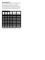
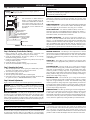
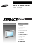
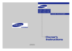
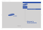
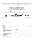
Instructions for Installation and Operation
Type UPM Unfiltered SCR Speed Controls for
Permanent Magnet DC Brush Motors
■
■
Model 0865, quick connect tabs for electrical connections
Model 0866, plug-in terminal block for electrcial connections
SPECIFICATIONS
Input Voltage:
115/230 VAC +/- 10%, 50/60 Hz, single phase
Max. Input Current: 8.2 Amps RMS at current limit with largest motor
Output Voltage (115 VAC Input):
0-90 VDC
Output Voltage (230 VAC Input):
0-90 VDC or 0-180 VDC
Ambient Temperature:
0-50° C.
Max. Output Current, Continuous:
2.1 Amps DC
Max. Output Current, Peak:
5.1 Amps DC
Speed Regulation:
1% of rated speed obtainable
with most motors
Acceleration Time: (0-90 VDC)
Adjustable, 0.2-10 seconds
Acceleration Time (0-180 VDC)
Adjustable, 0.2-20 seconds
Deceleration Time (90-0 VDC)
Adjustable, 0.2-10 seconds
Deceleration Time: (180-0 VDC)
Adjustable, 0.2-20 seconds
Means for Speed Adjustment:
10K ohm potentiometer or
isolated 0-5 VDC signal
Means for Drive Inhibit:
switch closure
Diagnostics:
green power LED, red current limit LED
R
INSTALLATION
WARNING: This control should only be installed by a qualified
person familiar with its operation and associated hazards. The
National Electrical Code (NEC), local electrical and safety codes, and
when applicable, the Occupational Safety and Health Act (OSHA)
should be observed to reduce hazards to personnel and property.
Step 1: Mounting the Control
CAUTION: Exposed circuit boards should be protected from electrostatic discharge during handling to prevent component damage.
CAUTION: Mount the control chassis in an enclosure suitable for
the application environment.
1.50
3.64
.50
(TYP.)
2.50 (TYP.)
1.25
.25
(TYP.)
3.80 (TYP.)
4.30
DIP SWITCHES
JP1
.09
(REF.)
.094 R. SLOTS
(6 PLACES)
.95
(TYP.)
FIGURE 1 – Control mounting dimensions
The control may be mounted with the circuit board horizontal or
vertical. The mounting slots in the heat sink will accept #8 screws.
Step 2: Preliminary Setup
INPUT VOLTAGE JUMPER – Fig. 1 shows the location of JP1, a 3-pin
header. A jumper is factory-installed for 115 VAC. If operating from 230
VAC, remove the jumper and reinstall it in the “230” position.
HORSEPOWER & OUTPUT VOLTAGE SELECTOR SWITCHES – Fig. 1
shows a bank of 8 dip switches. Set switches 1 thru 7 to match the
type, voltage, and speed ratings on the Bodine motor nameplate per
Fig. 2 (consult Bodine on settings for non-Bodine motors). Set switch
8 “off” for 0-90 VDC output and “on” for 0-180 VDC output.
FIGURE 2 – DIP Switch Settings
Motor Nameplate Data
Dip
Current Range Typical Input
Rated Armature Bodine Switches
Of TORQ.
Current at Max.
DC
Speed
Type
On
Potentiometer TORQ. Setting
Volts
(rpm)
(DC Amps)*
(RMS Amps)
130
2000
32A4… 2,3,4,6,7
0-1.7
2.8
130
2000
42A4…
2,5,7
0-2.7**
4.3
130
2500
24A2… 4,5,6,7
0-0.65
1.0
130
2500
24A4… 3,4,6,7
0-0.8
1.3
130
2500
32A3…
1,6,7
0-2.1
3.4
130
2500
32A5…
2,7
0-2.7**
4.3
130
2500
42A3…
2,5,7
0-3.0**
4.9
130
2500
42A5…
1,3,4
0-4.3**
6.9
130
2500
42A7… 1,2,3,4,5,
0-5.1**
8.2
180
1725
24A2… 4,6,7,8
0-0.2
0.3
180
1725
24A4… 4,6,7,8
0-0.3
0.4
180
1725
32A3… 4,6,78
0-0.6
0.9
180
1725
32A5… 3,4,5,6,7,8
0-0.8
1.3
180
1725
42A5…
3,5,8
0-1.3
2.1
180
1725
42A7…
2,5,8
0-2.0
3.2
180
3000
24A4… 3,5,6,7,8
0-0.75
1.2
180
3000
32A5… 1,2,3,6,8
0-1.2
1.9
* May exceed the continuous load capability of the motor–it is the user’s responsibility
to make sure the application does not exceed continuous rating of motor or gearing.
•• Max. setting exceeds continuous rating of control–it is the user’s responsibility to make
sure continuous output doesn’t exceed 2.1 amps DC in application.
INSTALLATION (continued)
Step 3: Electrical Connections
WARNING: The AC power line to the control should be the very last
connection made.
CAUTION: The control board signal common is not at ground
potential. Any external signal or equipment connected to the control must
be electrically isolated from ground.
WARNING: All parts of the circuit operate at voltages capable of
causing serious injury or death.
PWR. LMT.
All connections to Model 0866 are
made to a plug-in terminal block. All
connections to Model 0865 are made to
0.25” Quick Connect (QC) tabs, so all
wires need to be terminated with 0.25”
QC terminals, such as AMP 41274 or
equivalent.
REG.
JP1
S3
L1
A1
A2
L2
S1
S2
H1
TORQ.
MAX.
MIN.
DEC.
ACC.
H2
SPEED POTENTIOMETER – Connect a 10K ohm potentiometer (included with
control) to terminals “S1”, “S2”, and “S3” as shown. Alternatively, an isolated 0-5 VDC signal may be connected to “S2”, using “S1” as common.
MOTOR CONNECTIONS – For clockwise armature rotation, connect the “+”
motor wire (white wire on stock Bodine motors) to terminal “A2” and the “–”
motor wire (black wire on stock Bodine motors) to terminal “A1”. For counterclockwise rotation, reverse the motor connections.
Optional Inhibit Switch
(supplied by user)
10K Ω Speed Potentiometer
(included with control)
Fuse (supplied by user only when L2 is not neutral)
115 VAC or 230 VAC
Line Voltage
Fuse (supplied by user)
INHIBIT SWITCH (OPTIONAL) – A mechanical switch or relay with contacts
rated for low voltage may be connected to terminals “H1” and “H2”. With
the switch open, the motor will run. With the switch closed, the motor will
coast to a stop.
AC POWER CONNECTIONS – AC power is connected to terminals “L1”
and “L2”. A fuse (not included with control) must be connected in series
with “L1”. Use the information in Fig 2, along with any applicable safety
standards and with assistance from a fuse supplier, to select a proper fuse
value. An additional fuse of the same value must be connected to “L2”
only when the connection made to “L2” is not “neutral” and has a potential with respect to ground (such as with 230 VAC lines in the U.S.A.).
}
Motor Armature
FIGURE 3 – Electrical connections
OPERATION
Step 4: Preliminary Checks Before Starting
1. Before starting the control, check all fuses, connections, and
adjustments such as voltage and horsepower switch settings.
2. Check all rotating members. Be sure keys, pulleys, etc. are securely
fastened and safety guards are in place.
3. Check for proper mounting and alignment of products, and verify safe
loading on shafts and gears.
4. Check that motor is securely mounted.
5. Test the motor unloaded first to verify proper connections.
Step 5: Operating the Control
1. With AC input power OFF, set the speed pot to ZERO (fully counterclockwise). If an inhibit switch is used, close the switch.
2. Turn on the AC input power to the control.
3. Open the inhibit switch, if used.
4. Turn the speed pot until motor rotates at desired speed.
5. If the motor does not start promptly and run smoothly, disconnect the
AC power and refer to “TROUBLESHOOTING,” below.
Step 6: Internal Adjustments
Figure 3 shows the locations of the internal adjustment potentiometers.
WARNING: Use a non-metallic or insulated adjustment tool for
internal adjustments. Circuit components are not at ground potential
and accidental short circuiting and shock hazard may occur with conductive tools.
MINIMUM SPEED LIMIT - The MIN pot can be adjusted if it is desired for
the motor to run at a minimum speed higher than 0 rpm with the remote
pot set at ZERO (0 VDC between “S1” and “S2”). The maximum setting
(fully clockwise) produces an output voltage of about 50 VDC. Note that
increasing the minimum speed will also increase the maximum speed, so
the MAX pot may need to be adjusted.
MAXIMUM SPEED LIMIT - The MAX pot can be adjusted if it is desired
for the motor to run at a maximum speed lower than rated with the remote
pot set at FULL SPEED (5 VDC between “S1” and “S2”). The minimum
setting (fully counterclockwise) produces an output voltage of about 60%
of the full output.
TORQUE LIMIT - The TORQ pot can be adjusted to provide 0% (fully
counterclockwise) to roughly 200% (fully clockwise) of a Bodine motor’s
rated torque.
ACCELERATION TIME - Turn the ACCEL pot to change the acceleration
time. The minimum setting (fully counterclockwise) produces a voltage
ramp time of approximately 0.2 seconds. The maximum setting (fully
clockwise) produces a voltage ramp time of approximately 10 seconds
with a 0-90 VDC output and 20 seconds with a 0-180 VDC output. Certain
loading conditions may prevent the motor from actually accelerating as
quickly as the output voltage ramps up.
DECELERATION TIME - Turn the DECEL pot to change the deceleration
time. The minimum setting (fully counterclockwise) produces a voltage
ramp time of approximately 0.2 seconds. The maximum setting (fully
clockwise) produces a voltage ramp time of approximately 10 seconds for
a 90-0 VDC output and 20 seconds for a 180-0 VDC output. Certain loading conditions may prevent the motor from actually decelerating as quickly as the output voltage ramps down.
SPEED REGULATION - The REG pot sets the gain of the IR compensation.
It is factory-set so that motor speed varies no more than 2% from no load
to full load at full speed with the horsepower switches set properly.
Increased IR compensation can be obtained by turning the REG pot clockwise. However, this may cause some systems to become unstable. If this
occurs, reduce the regulation by turning the REG pot counterclockwise.
TROUBLESHOOTING
WARNING: Disconnect the control from the AC power source before
working on the control, motor, or driven equipment.
If the motor does not operate, disconnect the AC power and double check
all connections and fuses. Make sure the TORQ pot is not turned fully
counterclockwise. If a fuse is blown and the motor is not locked (stalled)
or overloaded, do not replace the fuse. The control may be damaged. If the
motor is overloaded, reduce the load and replace the blown fuses with new
ones of the proper type and rating. If the problem persists, contact your
source of purchase or a Bodine Authorized Service Center and describe the
problem in detail. Include all nameplate data for both motor and control.
BODINE LIMITED WARRANTY
The Bodine Electric Company warrants all products it manufactures to be free
of defects in workmanship and materials when used under Normal Operating
Conditions and when applied in accordance with nameplate specifications.
This warranty shall be in effect for a period of twelve months from date of purchase or eighteen months from date of manufacture, whichever comes first.
The Bodine Electric Company will repair or replace at its option, any of its
products which has been found to be defective and is within the warranty period, provided that the product is shipped freight prepaid, with previous authorization, to Bodine’s plant in Chicago, Illinois 60618 U.S.A., or to the nearest
Bodine Authorized Service Center. At its option, all return shipments are
F.O.B. Bodine’s plant or Authorized Service Center. Bodine is not responsible for removal, installation, or any other incidental expenses incurred in shipping the products to or from Bodine.
This warranty is in lieu of any other expressed or implied warranty - including (but not limited to) any implied warranties of merchantability and/or fitness for a particular use or purpose.
Bodine’s liability under this warranty shall be solely limited to repair or
replacement of the Bodine product within the warranty period and Bodine
shall not be liable, under any circumstances, for any consequential, incidental
or indirect damages or expenses associated with the warranted products.
Any Bodine product which is damaged due to misuse, abuse, negligence or has
been modified or dismantled without the knowledge or written consent of
Bodine, is not covered by this warranty.
2500 W. Bradley Place
Chicago, IL 60618
Phone: (773) 478-3515, Fax: (773) 478-3232
www. bodinemtr.com
R
P/N 074 00205A (ZS)
P/N 074 00205A (ZS)