1
''STYLYX''
USERMANUAL
0
h
t-i"
I T4TftGDUf,TI ilT.j
The
I!&R
*ixing
is
STYLYH
reccr-ding
it
Li=eE
creet=
The
a
=plit
pu-bLic
address.
de=ign
=y=-tera,
al I
and
easy
tr:
neceE=arlJ
whirh
ma.keg it
rnu=icia,ng
and
h*.ndl=
facilitie=
pi:==.ible
tc:
=lrbgrru.p=.
STYLYX
+.rsrk-
and
cc!$lFact
inrt:t-pi:rates
c.;:n=-*1e uhirh
fsr
*-t
ha=
arid
I t' = a
Tt:
becsne
fanriliar
!.rF
ed.;ige
yilrr
y{fli
in=tallatit:n
fsr
facilitj-eg
he*re
envirr:ninent.
giwe
s-n extre.rnely
ts
in
=ituatit:ns
ingdular
rrrnplete
L.iith
res.d
irnpcrtant
;.nd
life
a.l1
this
the
tnanu*I
inf
in
pr-cdr-rcer=
a
that
midi
ba=ed
the
STYLYH
=_ri=te*r,
f,acilitie=
very
,c:rsnatisn
t:f
It
rar=full-t'.
ab*:ut
t'tiIl
t:per-at!-ng
service.
IIEiH Electrnnica
F.V.
t
DN
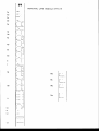
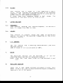
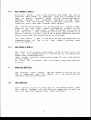
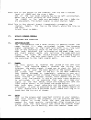
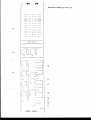
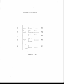
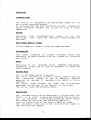
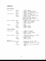
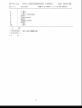
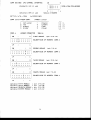
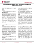
M O N O / M I C L I N E M O D U L ES T Y L Y X
2a
2b
2c
2d
+AAv
pad
phase
lne
.
.
2e
3a
3b
4a
5a
8a
1rtd
t"*""
14c
[:,""":"""
8b
l4b
14a
10
11
12
tl
L:"
L__"
?
STYLYX
HONS I'TODULE
The
channe+1
can
npnr-ate
in tlitherr
the rniri'-c:phcrne cr
line
-'i-npt-tt rncldes "
-fhe
j.s; an
rn.icrnphane
i.npr-rt
slectrnnically
b a .l a n c e d ,
tr*rn*f nrrnerler;g
design "
The
inplrt--,irnped,*nce
gr'€ater
iEi
t han
l:.*hms
?
whic fr wi I I not
cartsi,er any l nad i.ng ef f ec ts Llrl
"
'
tnd,xy
sr stlrcl in rnir rclphrJne6 .
I'hs
halanct*rJ
linrl
level
i.npt-rt whirh
a*f f ec'b. and tapa* retrrrn
h*si arn inpurt
1t{
F.nhmsl;, wl-rich
itigh
ig
ernnltgh
ava j. l.nble* ptrripheral
*qniprnent "
2.a
is alsn
tn be ursed as'
great*r'
impeda.nce
than
tc:
interf,.ice
*i1lwith
+4€l VBLT
+48 Vn1'L swi.tch
The
is there
tn feed
rnicrnphanes
rcndensnr
and
Direct
Injectinn
bcneg
t}rey have that
f ac j.Lityl
{ if
"
bJhen ur*ing
nther" rrricrnphane$
st-rch as dynamic
and elertric
{rnes n thr* phan tam pnw€rr EiLrlf,p
1 y * h a r - r 1 .d n n t
Lrt: rewi tc hetl c:n ,
i'JnTEs
I f
nhantnrn
i*
:ir^ritcheld
on nr nf f rartren the
l:ower
micrc:phnn*
irrpltl:
cfrannsI
isi a.ct.ive"
a "cIic!i"
fir "thl.rffip"
'f'hisi
yfiLl are
r ^ . rIi I
hear-d "
ig
becarrse
a
Lre
i.nterrltpti.ng
c li r - e c t l y
l.lic inpltt
standing
nf
val tage
on
the
snr[,:.et "
pharrtcrn po?.rer
Simi. lar'1y"
* , w . i t . c h i . n g f r n r n f ' lI C t c : L I N E w h i l * t
i.t;
rrri I I
have*
the
st*i tc h*d
cln r
same resi-r 1 t f c:r the *arne
rtlas'nn"
Thi.s ili rrtlt a far-.r1t"
f _ " '
?. b
FAD
pfid switch
[]r-rshi.ng
th*
the
insertr;
a ?fidB a.ttenlratian
intn
'l:he rnic rmplrcne
' a r n p. T h i s
l*hen
in pr-rt
c a r - t1 c J t l e n e r s ? s s a r y
r:'f
t:apar:j.'Lt:r
micrnphcnes
art*
tn
he
lrgsrJ
in clnse
mndern
'tt:
pro:{irn.ity
instrurnents"
Cven
S,I "
bsrtes, are
mLlsical
capairle
level
*ignalr.
nf pravlding
high
praviding
pad :iwitch
a
The
alsn
raise:;
the inpnt
impedanc*
hr;*lancmd Line
inpurt when the need *rriseg.
2.c.
PHASE
phase
The
revsrse
switch
rhanges
In rnnst case$ i{: is the
Lt1g!t!**_-g1lly"
r:t'f phase with annther solrrce.
.5
the u+iring
rnic xiqn*.l
nf the
that'g;
mic
n*t
2.d,
HIC/LINE
The
line
i.npurt is gelected
by purshing the
qain
rnic
redurced
inpurt
is
to
minimurn
c rosgta I l':. between
mic
and
I ine
in plrts
gain.
?.e
I'IIC/LINE
line
blrtte:n.
The
gain
tn
avoid
wi th inc rearing
GiAIN
The
rnicrophone i.nput can be varied
between +?CIdB and -55dF
gain.
pad of -3AdB increases
The
af
the control
ranq€* to
gain can be varied
55dB,The
line
i.nput
between *?OdF and
+:EdEi.
tloth
the
and Line ampl if iers
have their
rnic
own baLanred
amp is balanred
inpr-rt cclnnectars.
The
mic
on XLR. ( I is
is cnld nut c:f Fhage)
earth*
? ig hc:t in phase and.:
jacl.;" Tip is hato
The+ linsr arnp is balanr:ed toc: on a stereo
r-ing
When yot-l yse thie
inpltt
is
rt:ld anrJ shj.eld ig earth.
yoLr shnuld
a
lrnbalanced r
a.Lhlavs use
rnc:nn jacl.l u f nr a
:;tage performaflcer
m a , ' r i r n u r mi n p u t
3.
EEUALIZER
SEGTION
ot-tt by its
very
The
eqr-ral j"irer sectic:n
of the STYLYX gtands
the
of contrt:l
over
I t al lnwg 4 serctit:ng
e f ' fe c t i v e
design.
pass
the additian
with
of a high
sp€*ctrutm u
entir-e
alrrJio
f i 1 {:er $#r tion .
3r3
HI6H
PASS FILTER
in and crut nf the signal
is switched
The
high
FasF filter
p
r
t
*
h
b
r
t
t
t
o
n
.
The rt:l l of f of
1: rIB
path
asscciated
its
by
e
f
f
e
c
t
'
r
n
u
s
i
c
a
l
l
y
s
o
u
t
n
d
i
n
g
a very
at 1&0l Ha €nsltr€F
Notel
3. b.
If
be
the eq i:i switched
s;u,ritched nf f too,
offr
the
high
pass
filter
will
HI6H
at
llhHe'
with
a
is
available
c:r
c:f
boost
crtt
l.6dB
uuhen the desired
arnot-tnt
which
meansi that
cLrrve,
shelving
shelveg
from
that
reached
the curve
{rr
crtt
is
nf
hcrc:st
f re*qute*ncy t:n ,
4.
HI-FIID
SECTION
4"a
FREEUENCY
the
centre*frequtency
selects
T'hi.ri cnntrol
sectinn " I t range f rorn SOBH:I tc: lQll,;Hit.
4
nf
the
Hi*f"lid
4. b.
HI_FIID
This
contrnl
has
range
a
crf + and -16dtt with * "bell"
cLlrve .
Having
r e a c h e d i t s r n a ni r n u m / r n i n i m u m a t t h e s e *l e c t e d
amplitude
re'sponse returrng tn nnity
gain c:n
f requrency
the
ei the*r sicJe c:f that
se I ec terl f reqrrency "
plot
A
f rnm
that
respt:nse
shc:rxs a
bel L shape.
The
banrJwidth nf that bell
ct.rrv6*is fixed
at 1r5"
5.
LO-I'IID
5.a
FREEUENCY
Thi.*
selectg
the
contrc:l
band. It ranges frcm SOHI to
5. b
SECTION
cen tre-f
1kHz.
L.F.
the
rnid
?
the
sarn€r as t h e
f requenc iers b y t h e
Hi*mid
Lo*mid
CONTROL
The
has
lnus control
the high control,
l6dEt of boast c:r curt is
7.
crf
LB-I{ID
cantrnl
rs
doing
This
exactly
control
br-rt now
the selected
frequency
ccrntrol :".
6.
reqLlency
a
shelving
available
characterj.stj-r
at
jurst
like
6EH:,
EE-trN
c:ut f o r
can
sihritched
in
c:r
sectic:n
be
The
eqLralirer
signals.
and non equalised
camparing eqilalized
pass filter
high
will
in and
Also
the
be' switched
Nnte;
crlrt I
B.
AUXILIARY SECTION
available
in
Ther*
are
4
t\UX sendg controls
signal
br-tt tcr days extensive
seerns qr-rite a bit,
re*qurires a lc:t nf AUX send:i"
ci
This
total.
pracessing
B.a
AUX SENDS I
Altxili.ary
gwitched
ltsed
as
add re$tl
sessinns.
j"n*ertion
AND 2
sends
I and 3 are rrnrrnally pre*fader
bltt ran Lre
pa*t'*fader
if
desired.
They are intenrled to be*
gterecr
genrJs ciurring
f olclhacl,;
rect:rding,/publ
ic
pastutrerJ
se'tups
ancl
sri*i tc hed
rern i:t
cJlrring
The
AUX snnds
are
wj " r e d p o s t t r g L r a Ii : e r r p o s t
paint
and post channeL rnute switch.
fc:r autnrnating
it's
The
STYLYX has prnvixion
channel fader
pori tisn
hy
the
C-l'li n
f ader
alttornatinn
system " I f the
n*Mix
system
is
activatedo
these AUX siendg are wired ta
post in*ertion
post
paint
and Fr*q channel rnlrte
equalirer,
sr+itchn
rJne tn t.tre fact
that
C*l'liu cannnt automate
the AUX
Etrnds, when they are wired Fre-eq or pre-fade.
AUX sencls
I
The
j urrnpersettings
on
r n i c / I i n e r n n d r t1 e .
g.b
and
the
? can
p"c.b"
by
also
be tiet pre eqLralirer
jlrmper
see
setting
FagF
AUX SEND 5 AND 4
trired
pn*t*fader
crn the F.C"B.
bttt
stllnd
3 is ncrrmally
AUX
the
on the F.C"FI" hy rernuting
he changed
easily
this
can
j r-rmperxettinqa
assofliatecJ
"
j.nstructinn
jurrnper
(See
page for
rnic./line
mmdltle
setting
rnanual ) ,
in this
i.ngtal led
f,-l'4ix
is
1f
5.a,h.c.
?.
and
read
alsc
sectinn
RCIUTINE SECTION
inpltt
signal
T'he channel
the
and
S
ther
subgrclLtpE
pr-txh-butttt:n,
r-rr-rting
relevant
le.
activated,
ran he
6tereo
roltted
rniti !
nf
to ;rny nr all
by s e l e c t i n g
the
THE PAN-POT
(with a 4"5
cantrol
Tfris
the
between
*ignal
thla
the lef t and ri.ght master
pan6
pnint)
centre
dEt Logs at its
add and even sltbgrcrLiFs as wesl.I €\s
hr-rsso when sel,ected "
6
J-t "
*I{flI.INEL 5T*TU5
=EtrTIEN
11-s
The rhannel
sn gwit=h
ldhen a
i= indicated
by a green
led.
rnuted all
=end*
are s.l=t: nruted,
with
channel
i=
au.r:iliary
jacF:.
the exceptirn
t:f the =iEna1
tt: the
inserfartivated.
sectisn
I f
i=
instal
led
and
read
alss
C-l{ir:
5. a. b. =.
gwitch
The
sn
nnt
affect
the
=ignal
ccining
dt:e=
tr.f.1.
cna=ter
this
rnsde i= gelected
in the
the
f rsrn
channel
t if
sectit:n
] -
1:.
SGLO/FEAi.::
rnr:nitcrg!
acEtrrding
ts the eq.
The
channel
=slc'
=witch
-r-he rhannel,
pre-Eq
rfr
=ignal
the
t:n
=*ritrh
setting
pt:int.
past
A
=cls:
pr=t'eq
ingertisn
and
the
si-gna1
sith
the
tage*-her
indicates
the
rnaster
t*arning
led
in
is
that
leagt
sr:lcr sr+itch
led
at
one channel
channel
ssls
activated.
It
alsr:
indicate=
led
has
a
dr-raI
The
channel
FurF*st.
+
1
7
d
8
in the
r
:
c
c
u
r
r
i
n
g
a
b
r
r
v
e
l
e
v
e
l
=
=ignal
toverle:ad)
by it=
=crla push buttsn.
activated
l.lhen nst
=hannel,
level
in the
the =ignal
rnnnitr:r
r+i11
In
the-t
trae*e you
trs'i the
rnaster.
led inetering
by the
channel
I3.
f,HANNEL
FABER
glide
lEEl mc$ and i=
a
length
nf
ha=
fader
channel
The
g
r
n
s
s
th
g
i
v
e
l
y
f eel
in
e
r
:
c
e
p
t
i
o
n
a
l
a
n
ts
rnanlrf actured
aperati=n.
provi=ien
vclufie
it'g
tr-tr
autameti-ng
has
The
STYLYX
=y=temfader
autcrnstit:n
by the
C-t'lii:
cr:rrtr*i
14.
f,HAr.lf{EL If'UOUTFilTg
14.a
XLft input
i= the
This
I
Pin
micrcphgne=.
p
h
a
=
e
t
=
f
i
s
c
u
t
3
trin
14.b
fsr- balanced
cr:nden=ed
is earth,
trin ? i= in
irt:ldl.
t:r dynarnic
ph.e-=e ih*ti
a*d
ig h;:t
is baiancedr
The' tip
which
line
input.
aE the
Thi=
Thi=
t* earth.
is wired
ct:trC
and the =laeve
rirrg
i=
the
The
af - ?EdE rns-xirnrtrn ta infinity.
has a gensitivity
input
'=f
any line
cutput
ised
sf ??i.ishm r.*il1 nst
irnpedance
inpr-rt
prr:tre==Ers.
{rF sign.al
ta-pe rece:rder=
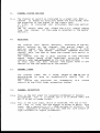
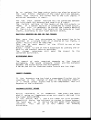
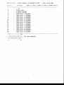
S T E R E OM O D U L ES T Y L Y X
16
17
l8
12
l3a
r3b
13c
13d
13e
19c
f,",:"",,
't9b
[
","":"",.
l4b
[*."*,,.,.
l9a
lsb
15a
r6
17
r- l
14.c
This i*; the nutpr-rt nf ths rhannel " The tip
has a naminal
level
crf *lOdFV and the ring + 4dBr-r.
fine
nf
the
twn level
antpurt* has ta be left
Lrnconnected.
Never lrse a rnono jackplr-rg on this
or-rtpr-rt,
'fnr
-l.mdFv
j.s
gemi pro eqlriprnent and the + 4dBlr fnr
The
prn equriprnent. The olrtpr-tt signal
i.s post channel fader,
14,d
(immediately
preceding
Thi6 isi the channel insert
the
channel
fader).
The
tip
is the returrn, while
the ring
tha send "
I n,/nlrt l eve I isi €]dFr-r
,
15.
is
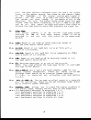
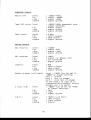
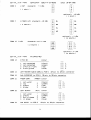
STYLYX STEREO I'IODULE
€iwitches
and
controls
16.
INPUTSELECTOR;
The
nf possihilities"
inpntselectnr
h a s a , r , ^ r i d ev a r i e t y
The
(L),
switch
when
activatedr
brings
upper
the incnming
(ancl
(and 1ef t) ( i,e.
:iignal
connected
tct
the right
ring
j
a
c
l
,
;
p
l
r
r
g
patch.
to the lef t signal
tip)
nf the
) input
activated
trlhen broth switches
are
at the sarne timel
left
paths
are
right
signal
carrying
the sarne rnonn st-rm
and
gwitch hrings
(F)
:rignal.
right
the incnming signal
The
(and right)
(i"e"
tip
of
ct:nnected
ts
the left
{end ring}
path,
signal
t h e j a c l . ; p l r - r g) t t : t h e r i g h t
L7.
PHASE;
phase nf the lef t l ine
reverse
ta
the
Uge
th j.s switch
the
hutt
inverse
wiring I
This
f eatlrre
doesn' t
inpurt "
the ar-rdio signal " A good F{ay tcr check f crr "nut c:f
inverses
putsh the rnann gwitch on the master sectian
phase"
is
to
rsral
close
t o t h e r n i x . I f y r r r - th e a r a a n e t h i n g
listen
and
miss.ing in yoLtr mitt
o
r
ccrtnFletely
that
riourndsi strange
"
pr.rsh the
phase swltch
on those channels sutspected " If the
that channel
was out af
souncJs hretter"
retlrrrrs
or
snlrnrj
selectarg
phase
the s:thers"
If ctne of the rnoncr input
with
yc:Ll wi l1 lose yclt.lr
poesible
that
is
it
is
activated,
AUX sie'nds, which are eltrnrning the lef t and
nn
the
sign*l
rigfrt
si.gnal pattrxo if ynt.t press the phase switch'
and the phaee switch
are
rnoncr inplrt
selectors
ldl-ren hroth
modut}e as
it even i:; pns::ibl.e tt: ltse the steren
activated"
is in
.i.nplttn where the ring
fr rnclnc: module with a balanced
phase and the tip autt af phase"
18.
GAfNr
cnntrnl
c:n yoLlr rnngole"
rnogt irnportant
Thj.s
is the single
p
r
n
p
e
r
l
y
r
y
n
t
.
l
s
e
t
achieve the very
c
o
n
t
r
o
L
c
a
n
hlhen this
get
and
the msst headroslrn
tcr nnise
ratic
best
*ignal
q r - r a li t y
Af ter plurgginq in a
recordings.
f nr
high
needed
j utgt abnve the channel
pr-rsh the
f ader
salo *ntitch
e i.qnal
with the channel fader- c:ff .
settin$u
on ther channel ycu're
I
Turn
ycrr-r se€ a 'r8rt rlr-rtpr-rt
the gain
corrtrol
lrntil
clccl.;wise
leverl
un the masiter rneters,
Nnw alide
lrp the channel
fader
't0ir.
tn
if
the
Remernber,
signal
scrurrce gets
lsurder nryc:Lr may
:;c:f ters
have:
to gn barl.:. and checl,; this
*etting.
vnlnme
yor-r bt:rrat nr curt i.n tha
The
can
also
clrange
if
eqlrali:er,
Bel silre
tlre signal
heing
miced *tays
the same
vnllrrne
when ynlr start
recordingu
crr yout'll
nesrd tn gc: bacl,:.
and
dn
tlr j.s; *rgain " Dn this
aI I
wi th every
1 ine
in put
to
qurality
achieve
the
hiqh
*crund D&R prodncts
ar*
l.;ncwn for.
12.
HI6H PASS
Thia
:iwi tc h
starting
at
i"n
swi tc hed
swi- tc h "
insiertg
180
H:
and
out
1?
a
dE
j"ntn
bnth
ints
the
rc: l-nf f
signal
circnit
hig h pass f i I ter
paths,
It can be
by its aggaciated
(baagt
13.a,
tlJEH.r Fcrost nr cnt 15dF at lll.;Hz shelving
rrrt the same arngurnt abave lll,;He).
13,b-
HI l'lID; Fc:trst or cnt
width of .1.5 octaves.
13.c,
LBhf l'llDr Boost ar cut l&dE bel1
r*itlr a width of 1"5 actaves"
13.d.
L(Jtrlr Bcrost crr curt 16dB at 6O Hz shelving
the sarne amoutnt below 6Ql H:r) "
lS.e.
in or nutt of the circnit.
EGl; Switches eqltal izer
ther hiqh FasE fllter.
NOTEI This also affecte
the hi.gh filter
switch.
16dF bel1
crtrve
cltrve
at
t:r
5 1 , ; H zt + i . t h a
sweepa,ble
(bc:oet
at
35OHs
clr cltt
It
nverride:i
14.a.
AUX l AND 2; Autn l and t are, most cctnmonly lrsed fnr cue
gends
(sterec:
can be eet
These
aLt!: gends
headphanes) "
jutmper seltinga"
pre/post
fade?r and/or eq by internal
alsn read se'ctitrn
activated
instal le,rJ and
I'f
C-f"li:l
is
"
5.a.b'r'
14.b.
sends
Can be utsed aa ef fect
AND 4;
AUX 5
These can be set pre/poct
mi.x for mr:nitoring.
eq hy in terna 1 j utmper settings .
15.a
15.b
c:r a. separate
'fader arrd./nr
you
anywhere
tn place the signal
Allowg
CHANNEL PAN:
the mix bltgs or the sltbgroLtps,
the sterea
image" feeding
to suthgroLlps 1 fr 3"
I-?r
Ass.ignment switches
3*4 : Aesignmen t sw.i tc her: tr: sr-tbq;r'clLlps .l fr 4 '
5*&; Aseignmelnt siwj.tches tc: sutbgroLtps 3 & 6"
tc: st-tbgrot.tps 7 & F'
7*Br Assi-gnment switches
mii: bltgs"
t n a ) {I A s g i q n r n e n t s w . i t c h e s t n g t e r e o
la
1n
I
channel
The
Eri switch
i= indicated
by s green
hihen *'
led.
chanr:el
i=
rnuted all
ai-rr:iliary
=-end= er-e al.=s rnlrted,
wii.h
jarl';"
the exceptii:n
sf
the =ign.a}
ts the
insert
If
anC
s=tivated
t-l{i:;
is
ingtel
led
read
a1=r: se,stirn
"
E-t--- - : : A r L : - r - E
The
srr
=uiif-ch
dcte=
frarn
the
channel
{if
=ectj-sn j .
nat
this
af fert
insde
the
tr. f - I .
ie selected
=ignal
in the
ct:rlting
rnaster
{T
ft*
rhannel
=c"iitch
=etting
pa=t-eq
=ignal
i*arning
led
=hsn:rel
=als
sr tii,.a,ted .
The
rha.nnel
=i-gna1
1evel=
cha*ne1
, i*h*n
3n
the.t
EaEe
channel
hy the
FADEF::
Ths
f adevP"C"E"
ha=
{n
=*1s
=witch
:*snitsr=,
a'E=r:rdi-ng te the eq.
ifn
the
rhs.nnel n
=ignal
the
Er
Fre-sq
gi:1r:
pcst
paint a*d
the
in=ertisn
A
in
the
rira=terindi=ate=
the
tt:gether
with
led th*t
at
leaat
sns channel
ssls
=i*itch
i=
purpcrEe.
led
ha=
a
dr-ta1
It
al=s
indicate=
+l7dE
orcurring
in the
ab{fve
{sverlsaC
}
net
acti.vated
by it=
sc:lr: pu=.h br-rtts:n.
yELr
+*ill
mr:nitsr
in the
the =igna.i
ler'*i
1ed rneter-ing
tlrr th= na=ter-
g'
is
l!!tr r*i* snis,=th
prt:'ri=ion
fsr- a C-F{ix
The
Etere{f
rentrtll,
parkageaut::r*e-tisn
actisn
fader
STYLYY STERE* HtrDULE f,NruNECTIilFi5
LiruE
EF{FUT
T}IRECT fiUTFUT
L/4"
1,f4"
=teres
Eterel:
j.=ck
jach
i tr
LE!-
I
ti\|rlj
i
ftINE
SLEEVE
ftIGi+T IhIFLIT
SIGN*L GRSUhIB
TIF
Left
at
+4dtsu
F:IFIG
ftight
at-r4dFr-i
SLEEVE
SIGIIIAL GfrEUl.lD
+4dFr-i
The
levelg
can
b=
changed
tt: -J-fidEV,
by
the
internal
ju-rnper ==tings.
RE},!ftTE
1/4"
=.terer:
jarF;
TIP
Flsrme. l ly r 1q:sed
HIFJE
Flcrrncal1y =pen
SLEELTE liliper
ctrntact
i?.a
plugging
in the
autpt-:-t= t:f drur*
ig
fer
Ii{FUT
u-ged
LINE
keybcrard=o
ilr any lin=
level
ru-tpui-.
rclarhine=r
Eamplers!
l-?.b
*UTFIJT
i=
S:RECT
=ignetr
r*i-11 ge!
it=
I t*
E FF4|.f TF
r
This
cc:nn=stsr
t'=
ch*nnslfase,r
indicatsr=
light
i=f the
channei'
t-t=sd a= F,n *u-tput
pc=t-- fader- e.inplif ier.
f i-ssi the
ts
=-+n
b= r.rir=d
=tart
rartridge
end Et: c:n.
it
a =+*itch
rnachine=,
sdhich
artiv*:ted
by
tape
deck=n
!LL'
'H
ro*
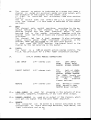
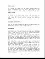
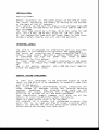
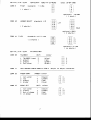
S U B M O D U L ES T Y L Y X
20a
20b
20c
2bd
20e
20f
2og
20h
20a
24a
2|']K,.
L.":"^
f"",.^^
24a
f -="*"
24b
24b
20d
20e
20f
2og
20h
f ,"=r."
^
2k,
L."'.
"
f"":"^"
. j ! J l
?E-a
?tr"b
i i t H t ' t i t l t ! t t
F
Ta.tre-:'effsct=
r=turns
T!-ti=- =witch
br-ing=
t-he n*nitnring
ints
the
:iisnitsr
=hang==
retrtrn
-
jacl= ir-lput
t-he =ignai
cr:nn=cted
ts: it=
=ectisn
t:f the
=u.b *redr-rle.
Thi=
=r.titch
input
fr-,=rn sub t:ut
ts tape.-re'ffect=
AUH l_ Am0 ?
The
AUH
I
and ? cc'ntrsl=
are
pu=hb'-rttan.
rnr:nitcr
by the
"pt=Et"
3El. =
AUH 3 AHP 4
The
*UX -3 and 4 c*ntrnl=
can be
gnanitar
jrrrnper=-etting="
b't intsrnal
=r*i-tchable
=et
frcr*
J-nter-n*lly
pre
-ts
tc
pr:=t
pre-ipa=t
?E -d
PAht*FilT
The
e.lith a center
Pan*pct
detent
and -: -4.=dS
dswr: *t
ite
pc=iti*n
centre
bet-wesn the
and r-ight
left
FanE the =igna}
rnix blrsse=.
?tr, e
FLIF
pr-t=hbuttrn
The
rearrariges
the
f Lser irt the
signal
" f I ip"
*iifnitsr
=ertisn.
If
the
=
r
+
i
t
c
h
i
n
it=
i
=
Lrp
"f1ip"
p
a
n
p
e
r
t
pa=iticn
t
h
e
r
e
c
s
i
w
e
=
=
i
g
n
a
l
i
t
=
f
r
s
n
r
t
h
e
r
n
*
n
i
t
r
:
r
n
f-he
ve:lurne
rantr-sl
.
l,{hen
sr*itch"
dswn ,
the
i=
" f 1ip
p.*n-pat
rereive=
=ignal
f,r-rrn the =*bgr=LiF
its
directly
faCer.
An ideal
=et u-p fsr
=er-ind reinfsrcernent.
pct
The
i**:nitsr
at
the
ss,rne
time
i= r*nnected
tr: the
jacF;
retu.rn
input
i+hi-rh dj-rect-1_v- fee'l=. the
tape,/ef
fects
yrru t*
*t-ttpt-:t
=ubgr'-cup
br-r==. This
feature
ail*:tr=
u=s {t}t:r-E
r-r=ing Lrtr any
rnili
feeding
the
bu==
c'rith*r-rt
inpr-rt
i,npi-rt
having
rnadltle=
Es t"rsli
a= nct
ttr give
Lip -irly subgrEi-iF=.
:tr- f
I-IilFIITftE
pi:t either
fsllsr+s
The
r*r=nitsr
the =ubgriflrp ar-itpr-r-i-t=r the
uptrn
Cependent
the pasitir--rn sf the "r-ef-Lr.rn"
tape
retu.rn
pur=hbr-rtt**
If
th* "=plithuttu-n"
=r.iitchi= a=tiv-=ted
ths
ir.nrr{-=ign*, I r:nly fr-ar* the retrrrr'
r*t:nitr.r receive=
it=
?fi " g
*F.i
The
cin-sgif-rh
*'rith
its
eg=t:=is+*ed
lsd
fl:ute=- the
=hannel.
29,.h
SBLO
This
switch
brings
either
the sutbgroLrF olrtputt signal
to
gection
the
rnonitoring
or
the
subgrolrF monitor
inpr-rt.
Thits is depenrlant Lrpon the staturs of the re,turrn switch.
The associated
led elso actg a$ a peak. indicatnr"
There are twc: irj*n tica I sec tinng
in this
r n a r j uI e ,
?E.i
FADERS
T'he twn
faders
contral
the crlttputs of the twcr slrbgroLrps"
positian
into
Lrpon the
the frame, this
can be
Dependant
sr-rbgroup
L/2,
A ' /4 |
5./& c:r 7 /4. The F "f,, B, has prc:vision
pacl.;age.
fc:r a C-l"lix fader alrtomation
?4.
IN AND BUTPUTS
24.a
Patch points
just
wired
ahead trf
These
are
ring
is
the
"send" and the tip
nf OdFlt (773 mVl .
ncrrninal level
2.4.b
Taoe
subgroL(p
"retLlrn"
faders.
The
both have a
A/B
j acl,;g bath
These
sterec:
c
h
a
n
geahle via
in,/outpr-rts,
?l.c
the
the
have
jltmper
*lAdBV level
+4dEtut and
settings
c:n the board'
Return
A/E
jacl,l sncl,;et is the input
fcrr ef fect
retr-trns"
This
sterecl
+4dFr-r and -1OdFV level
in one jacl';. The
have
They
both
+4dEtt-t,
and the ring
fias the -lCIldBV sengitivity
tip
14
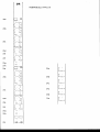
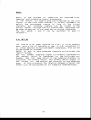
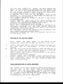
M A S T E R M O D U L ES T Y L Y X
la
710
-
13
-
20-
:l
10 |
'l
1b
rd
lc
1i
1f
th
;
19
1i
1k
1l
FTASTER I'ItrDULE
The
r n n d ul e
af
the
STYLYX cnntains
master
al l
the
for
sumrning of thsr l ef t./ rig ht signa 1a ,
electronj-cs
the
the
aLr!{ eignals,
wel l
as
aF
the Cantral
Fclom l"lanitar
sertion "
c:f
The
width
this
rnodlrle ig ?3 mm, (tr tirne$ the channel
r n o d l r1 e , s t e r e c : m o d l r1 e . / b 1 i n d p a n e I - 1 s n b g r o u g : m o d u l e ) "
1.a.
POhIER SUPPLY STATUS
pc:wer has been
T'he nn
leclg
L:n thq* ledbar
indicate
that
send
to the STYLYX. +/- le} Volt far the electronicg
and +
4el Vnlt
fcrr the phantorn powering
nf condenser
rnicrophnnea
bnne*.
and D"I.
1.b
AUX RETURNS
Ona connected
tn
The
two stereo
at-tli retrrrns.
STYLYX hag
to the R'-mix buss" A
the
steren
L*mix burss and the sther
pr-rshl:r-rtton switch
can rc:lrte the stereo
aLri'i r-ett-rrn signal
ther same time to the resp. AUX l and.? bursses. This is
at
prnvide
*ignal*
ta the rnaster as wel l as
tn
ct.re ef f ect
a
n
d ?).
A
U
X
I
f
o
l
d
t
r
a
c
k
s
y
*
t
e
r
n
the
{mostly
1.c
AUXILIARY I'IASTERS 1-4
handle the olttgaing
levele
ttr the 4 AUX
rnntrols
The*ge 4
c:n and a pf I
outpr-rt
hag
an
aasc:ciated
Every
or-rtplrts,
The
the signal
tc tre mrtted and rnonitared"
hr-rttnn
tt: allnw
by
when necessary
can
be
camputer contrslled
clr-r br-rtton
the aptional
"alrtomatj.nn tnodLtle"'
1ed" It also
is a dutal futnctioning
solc: led indicator
The
crverlc:ad in the AUX outtpt-tts,
i.nclicates
1.d
OSC I LLATOR/TALKFACK 5ECT ION
sgcil latnr/talhbacl';
a
multifttnctioning
STY[.-YX has
The
chnice
nutt of ? f requtenc j.esi 301 Hr
There
is
a
section"
( f nr
pLrrpo6e6,
to
i.dentif y
f ast
winding
ideal
slate
The rpd
up nlttputt sections.
l:.Hu fsr
lining
anrJ I
tapes)
and
the law distortion
oscillatnr
hr-rtton activates
o,sc.
whether .TE l"{r
bltttnrr beltrw, givets a choice
red
ther next
buttons
are rnltting
The ner:t three
ll..Ha is necessary.
crr
ts the mix buases n
tlre
ogc1t. b " signal
tcr send
blrttnns
tfre qrnr-rp Lrr-rsget; sr./arrd the AUX I and 2 ttltsgeg'
1eve1.
both the talkbacl,; and nscil lator
Iev*1. adjltsts
The
an x 1 r connec tor on the bac l'; is
ta I k Lrar l,l whic h
has
The
above the right
by the tall,;bacl,:. buttan situtated
activated
t
h
e
m
o
d
u
t
l
e
,
in
s,ame
rnag;tsrr fader
t6
1.e
I.IIINITOR giECTIBN
part
yoLr monitor
This
at
the
STYLYX lets
individnal
rn$no c:r
in
steret: o the
rnaster
mir , the AIJX
channels
gtereo solrrces"
(tape A" tape El)
aurtpute and twt: external
It
is
this C,R"l'1" signal
that is constantly
monitore'd hy
the ledbar meters"
l-f
TAFE
A/F
These
switchesu
when
activated
n connect
tc:
the
Control
Roorn
Monitnr.
i.nputs
yc:ltr gtereo
fnr
rnachines.
intended
master
+
IAdFV
4dEtr-r lever1 chsice
is
A
and
page ) "
p. c. h " ( siee j nmper setting
1.9
external
sterec:
These inplrts
are
available
itoN(I
provides
yot-t with
a rnono compatibil
Thig
burttan
the
left/right
S
u
t
m
m
i
n
g
the
stereo
signal
af
"
nlttpr-tt,
wi I I not af f ect
the rnain sterec
channels
1.h
nn the
ity
checl,;
mnnitc:r
H0NITOR./C.R.l'1.
gtends
This cnntrt:l
far
Control
Room Monitnr,
t],H,M.
j
r
n
a
i
n
L
t
o
t
h
e
r n s ni t n r i n g
s
i
g
n
a
u
r
s
t
s
t
h
e
o
u
t
g
a
i
n
g
ad
the olrtpurt af the
This
can
he either
signal
arnplif ier.
ot-ttpt-tts crr an external
solo
system, the mast€r left,/r.ight
(3 track)
signal " The norninal olttpt-tt is +4dEtut.
control.
are nc:t affected
by this
The ledbarmeters
1 i
PHONES
panel nf the
rlteren
lncated
c:n the f ront
olrtputt n
This
p
o
w
e
r
for headphcnes with
morJule i:s a high
autput
rnaster
drn irnpedance between f;l and TAAW trhmg"
phanes
be
adjusted
the
cc:ntrol
level
can
by
The
contrnl.
independant
frtlm the monitnr
(crmi nuttputts ar€ fed frorn the
phones
and
rnoni'tor
Fath
1.j
gafne
snLlrcg*s.
DII,I
T'his
buttsn
nnly
attenltates
L7
the
rnonitar
leve1
by ?AdF,
MASTER IN/OUTPUTS
2a
f"'^.
2a
[-*'
2a
2a
[^."".
2b
[,.*."
2g
f ",:" L.:,"""
[."*_
["*.
[.
^
",",-,"
2d
2d
[",,.."""
-rtl
2c
tt ll
|
-.'shc
2c
+tefr
2f
Monitor = 2e
t.k
TALKBAtrH SEtrTION
Tlris
swi tc h
rcrr-rtes
the
te 1 l,;bac l,; t c : t h e m i x / g r o u r p / A U X I
and
3
busses. At the sarne tirne it dims the C, R. H " nutpr-rt
by ?AdB tn avoid
f eedbacl,; "
1.1
sOLtr/LED
1f
anyuuhere in
the
console a solo br-rtton i.s activated,
lights"
this
led
Yor-rhear the gelected
signal
instead
af
the
Lrsllal rnagter mi:r at the phcrnes ernd crm nutpr-tt" At ther
selected
same
time
the
signal
is
rnonitored
at
bath
l ecl barrneterg ,
2.
I'IASTER IN/OUTPUTS
part of
This
the
external
power amFs,
2,a
AUXILIARY
the STYLYX provide;
equripmento
such
truTFUTS
al lc:ul
Thege
4
outtpurts
proce*sors"
and/or
signal
I eve I
is
The
nlrtgaing
cc:nnected to earth.
2.b
al1 the connections
with
processnrs
a6
signal
and
tn
cnnnec tion
+
4dBlr
c:n
tip,
fnldback
The
ring
arnps
is
INSERTS
to the rnaster
are
devoted
Two jacl,;s
is send,
is
€ l d E t u r .T h e r i n g
Tfre
level
are prnvided
tcr insert
These
?
insertg
deviceg
:lntn ther steret: mix immediatelv
faders.
?.c
the
ingert.
left/right
the tip
is retLtrn.
nr other
limiterg
before
the master
yrlt.t wi 1l f ind
the balanced
the
back !
lncated
at
Also
c:urtputts of the $TYLYX " Signal
level
is
rnester
lef t/right
+ 4clBt-t.
f ltlly
: j.g hot,
3 is cold
The
x 1r
are
balancsrJ
olttpr-rts
If
the outpLtts
are utsed in an ltnbalanced
and
1 is shield.
yout
pin f, to earthn
ntherwiee
always
cnnne,ct
environrnento
qet
auttputt .
a
dec reage
of 6dB signa 1 l eve I nn this
uri I I
settings
can
be
set
tt: *l0ldBV
hy jumpe'r
on
The
ourtpr-rt*
(see jutrnper setting*
pages)
the p"c"b"
19
2.d
? TRACK A/B
jacl,;g
Thege
I
accept
ei'rternal steren
tracl.:. machines"
The
tip
of the jacl';,
ri.ng
the
is
the
right
The
input .
-lAdFV
+4dEtU on the
changed
frorn
to
The
STYLYX eaeily
interf aces
with
rnaster machines.
2.e
sources such as 3
is the ]eft
inpr-rtu
sengi tivi ty can be
p"c.b"
by jr-tnpers"
tr:day's
twa*tracl,;
c . R . l ' 1.
'Ihis
gtereo
the
is
olttputt af the Contral
Roorn l'lonitcrr "
connec ting
ig
used
f or
i t
tc: your rnain
and
nnrrnal ly
Nominal
level
is around + 4dEtu" Tip is left
amplifiers.
right,
Da not loacJ thie arrtpr-rt with B ohm
and
ring
is
headphnnes but only with 5O€} ohm ones and higher.
?.+
POWER
powered from an external
heavy dt-tty Fower
The
STYLYX is
The
ar-tpply vol tages of +/* 1S Vol t and + 48 Val t
sr-rpply.
pc:wer supply "
sutpply ig
The
the
f lrsed
in
ar{e
Ftrwer
by way af a 5 pin XLR type of connector"
ccnnected
2.9
AUX RETURNS
jacl,:.s accept
f rom *16dEtt-t in
signals
down
These
will
be fed
r
i
g
h
t
)
a
n
d
r
i
n
g
i
s
is
left,
ttip
o
r
b
t
t
s
s
e
s
.
a
n
d
A
U
X
magter
3fl
stereo
to the
BPERATION
INTRODUCTIBNI
The
STYLYX is
deeigned
tc: be the perfect
antswer fcrr a 2
to 16 tracl.; recording
stutdio,
get rnc:re familiar
with the STYLYX we shalI
Ta
discuss
the
prcrcess
whale
recording
and
divide
it
inta
4
basj"c
SeqLrenceg
!
RECBRD
mj . c r o p h o n e / 1 i n e
in plrt
c:n
tc:
the
courld
be
f rsrn ctne or more channelg
at
f rorn
Recnrd ing
'f
mul titracl.,;. "
his
the time.
I'IULTITRACK REFLAY (SYNCI
In
this
rnade yolt
ligten
to
what
has
been recorded,
OVERDUEBIN6
to
This
rneans l istening
trn spare tracF;s,
recording
wi th rnnsic ,
a I ready
recorded
trac l.;s and
nnti I al l tracF:.s ,are f i 11ed utr
REFIIX
t:f
al l
Replaying
processing
reverb
mixdcwn "
final
recorded
tracl,;.s together
usith signal
tt: create
the
and al 1 that is necessary
RECORD IIODE
nf e gessit:n.
T'his is the beginning
a
r
e placerJ in the rnic rnode by leaving
Al l
inpltt
channels
gwitch
Fhantnrn
in
l ine/grot-tp
the
Ltp pc:sition,
the
powering
in the utp
applied
if
necessary"
Eq. switch
ig
pnai tinn "
and
through
the
fader
ig available
The
signal
fLsws
postfadern
at the nurtputt"
at the bacl,; af the channel,
*iEna}.
T h e l . s * t Jb a r r e a d s t h e n l t t g o i n g
FIONITORIN6
can he monitnred
in variourg ways" The
The
recorded aignal
spl it
console
a n d t h e r e f o r e t h e r n l r lt i t r a c l . ;
a
STYL.YX is
in the snbgroLrp rnnduleg" Every rnodurle
r*i11
be
cnnnected
nachine"
t
w
n
t
r
a
c
l
.
;
s
of the mnltitracl,;
c*n accept
*1OdFV or +4dBlt"
There is a chnice ourt of twn levels
prrts
wi I L bring
the mlrltitracl,;
signal
tn
The
monitaring
t h e Le f t / r i g h t m i x b u r s s e s ,
"1
an
aption,
the tape retLrrn jacks can alsn be wired ta
As
the
last
4/A/ Le
channels crf the inpnt
m|c/ l ine rnoduleg.
Thege
tape
returns
are norrnal fed tn the line
inputta, A
in remix "
sitlratisn
necessary
The
machine wil l be connected
two
tracl.;, masterr
between
the leftlright
XLR ot-ttputg and tape A or B inputt"
The
factnry
setting
nf the levels
at the XLR t:r-rtplrts is
+4dBU,
a rnaster rnachine it; connected
If
ta these olrtpr-rt,
yrrt-r rnay f ind
it necessary
to change the jlrrnpers setting
the levelg
at
the p.c.b.
ta adjust
at the* ourtpt-rts cr tape
inputs,
according
tc: ynur tape ma.chine leveIs.
I.IULTIPLE
SOURCES ON ONE OR ThITI TRACI(S
than
rnicrophone clr line
signal
has tcr be
When rnore
one
or in stereo
on twn tracksn
a
recorded
on
a single
track
will
be requrired.
s u r h r n j . xf a c i l i t y
nn
STYLVX by way af the
This
be
done
easily
the
can
rourti.ng *ystem "
by plrshing nne $r
rourte
tn nne af the S subgroups
Simply
switches"
more of the channel roltting
gend
the
signa 1
to
the
sltbg rc:t.tp:i wi 1 I
Th**
c fl$sen
connected mnI titracl,; .
I'IICRSPHBNE 6AIN
gain
depends
crf
required
amonnt
The
pressllre
level
sound
the
rnicrnphone
u
between
the gc:urnd *t:Ltrce and rnicrophnne.
where
levelg
A 3A dF Fad can be ingerted
INSERT
on
and
are
the
the
tao
type
of
distance
high"
trHANNEL
can be
the
dynamics are tcro high a cornpresgor/limiter
If
the
channel t:r sven in the subgroLlF ineertu
in
inserted
whal,e groLtp xi.gnal has to be compresged " This all
if
a
depends an the sitnation.
FOLDBACK/EFFECT
SENDS
that every c:ne hears
ig
essential
recrrdin6
it
Durring
g o i n q o n . H e a d p h a n e m i i . e s a r e L t s L t a ll y d e r i v e d
f rnrn
uuhat's
pr€, fader AUXILIARIES,
purp$Fer
and 3 are
ideal
for
this
the
STYLYX AUX I
In
rautted
tn these
hutgcies.
is
the tall,;back
while
especial ly
the AtiX sends
fram
subgrflLlp
is
tn
derive
The
Lregt way
n e e f u rI
f or
dlrbbing
Thi*
set
Lrp
ig
very
channeLs.
:iituations
"
:3
EFFECT SENDS
can
All
LlnLrsed AUX sends
be
ltsed
to gend signals
ttr
prncessorso
sr-rch as
de1ay. The AUX
signal
reverlr
and
poat
lrsural ly
f ader
tn always l';eep the right
sendx
are
signals.
balance between urntreated and treated
EFFECT RETURN
To
the
effect
an tape it
hag to be mixed with the
hring
Replay
the
ef f ect
in
an
u r n u t s e c ,cl h a n n e l a n d
original.
ronter
channel by the routing
buttons"
it tc: the recording
the
ther EclLrrce criginal
through
sutbgroltp
Alga
send
systern,
I.IULTITRACK
This
is
replaying
RFPLAYIREFII
X
digcltssed
al ready
done
is normally
in gectisn
I (recnrd
throurg h c hanne 1g ,
mode) but
OVERDUBBING
prcrcess
is
the
Lrp a recording
Overdr-rbbing
nf
bnilding
recorded
whi 1e
l istening
to previoutsly
trarlt
by
trach,
c
h
a
n
n
e
l
s
w
i
l
l
b
e
i
n
t
h
e
m
i
c
r
o
p
h
o
n
e
mode
tracl.;s "
Snrne
are rep l aying
r^lhi l er others
the rnlrI ti trac l'; .
tracl,;g
are
mc:nitored
in
the
alrbgroup
The
rerplaying
modutl es .
can be best rni:.red frorn the snbgrc:up
Headphone
monitoring
has tc: be nade as to
AUX 1
and
3 gends" Here a decigic:n
t:f
f rom
the
soLlrce
the lreadphone rnin" It can be derived
surbgrcllrp channel or hath.
It is urp to
the
inplrt
channel,
yt]Lr "
channel
the
mursician wi I t hear himsel f
Frorn the
input
previalrs
recorded signal
A
an that track"
only,
not
the
ulay nf headphone mirr today is as fnll(f,wsr
rnost
convenient
todays
m l tI t i t r a c k w . i I 1 g i v e t h e i n p u t s i g n a I a t
f'lt:st
of
i
n
recnrding.
its or-rtpurt when
h
e
a
d
p
h
o
ne
mix
frnrn the tape, As long as tha
Derive
the
j.s
the
rep I ay
msde the rnusic ian wi I t hear his
tape
in
previouts
tracl,:.s and the rnament the errgineer
recorded
Ec:€rs
record
he wiLl
hear himself
life.
This method 6ave6
into
f r o m c n n t . i n u a I I y s w i t c h i n g r n o ni t c : r s c : u t r c e s .
the eng ineer
AUX xignal
from the r-ecording channel the
adding
the
Fy
rnlrsiician
wi I I hear himsel f bef nrs* the rnoment nf recording
goe6 intn
the
mltltitracl,r.
recarding
a
As
tnn"
s.ot]n a6
in the level will
be heard. Not tao bad,
slight
increase
mnsician
trxactly
l':.nowgthat
what he ia daing
the
becaurie
will
he reccrded.
rr:.jl
REI'IIX
process
Rerni:< ig
the
c:f
cnrnbining
al l recorderd tracl.:.
processing "
together
Flith entengive
signal
are norrnalled to the line
In
the
STYLYX all
tape tracks
ta
inplrts
inpltt channel " It j-g anly necessary
af the last
rnicrr:phnne
in
switch
the
inputa
to
I ine
the
in/out
ronted
signals
can
be
tn the
channslg"
A11
incoming
rnagter
throurgh the mix pr-rsh-burtttrn, $urbgrot.rFs can
steren
recording,
be rnade as desired
in the same way as during
The
Anx
ng'fre55ary
P.A,
sends
I
and
?
can
be
gwitched
to
po*t
if
"
SET UP
console for P.4".
It is scr cnrnpact
T'he STYLYX ig an ideal
it
in Ltser, In F,A. situationg
even
with a lc:t of channels
j-s
This can be
often
deeiired to have Ferrnanent *ubgroups.
acct:rnpl ished as f o1Iows.
the
and activate
onet or rnore sltbgroup channels
Rt:r-rte to
Lrurttan.
"Sp1it"
connected ta
is directly
Now the
summed surbgroup signal
mi;'t
panpot
tn
the lef t/right
wtrich
connected
is
the
"
1g
i n t h e s r - t b g r c : t - t pc h a n n e l g
tape retltrn
bursseg,
Nnw the
signal
is
f or ef f ect retutrn " This ef f ect retltrn
a.vai lable
pot directly
to the altbgrc:Ltp
via
the monitor
ralrted
now
and
between original
the relatian
situation
hrltss.
In this
on a1l surbgroltp f adersetting*'
slf f ect wil l he maintained
:4
CBNNECTOFS,
U.[III] .cllfr$NEi",i
XLfl in purb:
level
tip
r j"ng
:i l eeve
; *7Q ta *3trdF
grnurnd" (screen)
r signal
(in phace, hnt)
l signal
; signal
{crurt c:f phase, cold }
r -?O tn infinity
(in phase" hot)
l signal
( outt c:f phase n cold )
; signal
grolrnd
r signal
If this
inpltt ig lrsed in an
urnbalanced mode, alway*
cnnnect the ring
to earthr
Gtr
LrFe a mc:ncljacl.;.
I -'l0dElV an tip + 4dBU nn ring
; signal
lcrw (-lAdBV).
: s i g n a t h i g h ( + 4 d f { U) .
greurnd,
r signal
level
tip
ring
sleeve
;
:
;
:
0dFU
rignal
signa I
signal
level
tip
ring
sleeve
:
;
;
:
-.l0dF
level
I
f-i-nr
ring
g1 eeve
l
;
:
+4dEtu { can be set
by jurmper eetting).
left.
*ignal
right.
signal
ground.
signal
level
tip
ring
;
;
!
sleeve
:
level
pin I
Pl.r
Line
inpurts r
Direct
Insert
or-rtputa;
r
I
s
pin f.
level
tip
ring
sleeve
inplrt"
o u r t p t - r t"
grannd.
$TEREN -QHANNEIL j.ne inpnt r
Direc t
autpurt l
Optional r
Rernste connector
:5
signal
signal
signal
to inf inity
"
(in
phaeei
( out nf pha:ie )
graund.
to
*ICldFV
maximltm t:f ?4 Volt
5OE mA,
rontact.
changeover
cnnnected
when fader
tn tip
high "
to tip
sannected
when fader
down.
su_qgiR0uFII0DULF
Retlrrn
A,/B
Tape A./B in/c:lrt
r
r
r
l
level
r -10dFV/+4dFr-r dependent
j urrnper settings.
; signal
inputt.
r signa I crutpt-rt"
: signaL ground "
tip
ring
sleeve
pnint
-16dBV/+4dEtr-r.
-lAdBV.
signat
+4dFU"
aignal
signa I grnltnd "
1evel
tip
ri.ng
sleevs
ring
sleeve
l
l
;
r
fl dBr-r.
returrn eignal .
gend signal.
gronnd,
eignal
AUX retlrrns l
level
tip
ring
s I eever
;
:
:
;
*1OdSV
signal
left
signal
right
grnutnd
signal
AUX or-rtpt-tts;
level
tip
ring
slesve
i
:
:
:
+4dFt-t
(in phase"
signal
not connected
signaL greund
level
tip
r5.ng
sleeve
;
r
;
l
OdEt
signaI
retnrn
send signal
grannd
signal
Fatch
level
{L -T F; ' ^
uporr
PIA_STER
fl!]putE
I nserts
;
l"lagter
ourtpr-rts l e f t / r i g h t r
? Tracl,; A/B:
c.R"l'l
:
hc:t)
tip
ring
gleeve
level
: +4dFr-r (can be set tn
.-lEdBV by jLrrnper setting)
pinl
ground
;
pinl
:
hot (in phaae)
(or-rt c:f phase)
pin3 ;
csld
I f the ourtpr-rt is lrsed in an
always
nnbalanced environmentr
connect pin 3 ta earth,
r *10dBV tcan be set tcr +4dEtU
hy jLunper settings)
r left
; right
r xi.gna 1 ground
l erve I
tip
ring
slesve
; +4dEtU (1"3: Valt)
: left
outtpr-tt
r right
crurtpurt
: grournd
level
36
Fnwer
( XLR) r
Ta I l,;,bar h
pi.n
Fin
pin
pin
pin
I
3
3
4
5
:
r
r
;
r
grnund
+le Volt
-lff Vnlt
phantom (+4dEV)
grolrnd
clrassis
: *70ldBur * ta -.l0dFut.
: grolrnd
: hot in phase
: ground"
level
pin 1
pinl
pinS
77
INSTALLATIONI
Applying
Fcwer;
Fefnre
switching
trn
the power silpply of the STYLYX check
c:f the surpply by loal.;ing at the sticker
the
maing
voltage
on the bacl,; c:f the 19" housing"
he 11O Volt for area's
This
ehnrrld
with voltages
frarn lOO
tn
13O Voltg and 338 Volts
fnr area's
w i t h ? 3 @ t o ? 4 C I 1V o I t
main voltaqes,
Tlre main futse shor-rld be 3.15 Ampn 36 rnm Anti
surge fcrr 3?CI
VoIt,
and 6.$ Amp, ?0 mm Anti sLrrge for 11O Volt area's.
Dn nnt replace
the furge with any other
typer f,s this
cor-rlrJ
haaard, and will
voirJ the warranty"
bercome a safety
INTERFAtrE
LEVELS
The
STYLYX is prepared f nr interf acing with al l avai lable
cnn f iguratian
aee Sonneqtqf-js .
e q u r i p r n e nt i n i t s s t a n d a r d
fJne perin t
atten tinn
h a : i t o m a d e c o n c e r n i n g t h e C " R . M.
of
nlttpr.rt delivers
a nominal +4dFU level
which
r:lrtpr-r't" This
power
trigh
fc:r
isi
too
arnps rated
at SOOmV
sc:metirneg
f or f lt11 nlrtpt-tt"
sen:iitivi.ty
In
thnse
install
an input
a.ttennator
case6
at the power
+4dElU level
by approlrimately
arnps irrpr-rt to redlrce this
1I
clE{"
resistor
and a 68O ohm ghltnt resigtor
Use
a
31,;3 seriefs
input"
across the amplifier
GENERAL }IIRIN6
PROCEDURES
full
t:f the excellent
signal
to nctise
To
take
advantage
to carefutl ly read this
ratio
trf the STYLYX it is neceqsary
part of the manutal.
interfererncen
bltrresi
instability
are
Hurno radict frequency
and
earthing
wiring
inferior
t:ften
cat.rsed by
irnpraper
the
incoming
maing
earth
is
nnt
systerns.
.$nrnetimes
earthing
and
a
separate
technical
adequrate
fnr
sturdio
erarth has tt: be rnade for ;rl1 the autdia eqltipment"
give
ycrlr aI l the
r:iupply
cornpany wil l
Yourr electricity
regltlatians"
cJetailg to avt:id ingufficient
safety
tc: be follawed"
T h e r e a r € s o r n € ?g r a u t n d r l t l e s
in
a
studia
are
referenced
ttr eartfr" This
All
aignals
paint
hag
A central
earth
tcr be clean and free crf noise"
t1ecided fnr the rnain eartlr point
eystem and al1
shor-tld be
point.
frcn this
shc:r-rld be started
earth*
T8
The
e,,ay yt:t-rr electricity
cornpany
has daisy chained
the
j.g ltnsuitable
earth
in ycrLrr situtatinn
for yoltr str-rdj-o. The
hest
way
is ta rt.rn a separate
earth
wire frarn each ot-rtlet
tn
starpoint
the
systern
earth,
Tlris is th* safety
earth
yollr eqlripment.
and screen reference
far all
A separate
wire
f rnm
al l
the
eqlripment
racl,;s
to the
starpoint
via
it;
nice tc: have in cases where the earthing
mains p1r,rg* ig not satisfyi.ng.
The
rtarpoint
sholtld be lacated
at the rear of the ct:nsnle
nr- equipment
rarcl,:..
c li r t y "
tnains
Install
separate
"clean
and
or-ttlets.
The
{f,nes fc:r auclia equrip,nent and the "dirty"
onFE fnr
"clean"
freesers
liUhting!
air*conditioningo
and t;c: t:n"
Do not min up these twa gc:rts of or-ttletg.
l'lains
born
interference
can be isal.ated
by introdurcing
an
j.serl"atinq
trangformer
for
the
olttletg
the
clean
earth
transf crrner
tn the technical
earth clr as c lc:se as
directly
pc:xsible to the incoming earth,
Al l
erquiprnent
to
be located
as f ar ag pnssible
f rnrn
iras
the incarning rnains distributit:n
boxes.
Unbalanced
eqlriprnent may rreecl to tre isolated
from the racl,;
tn avsi-d earth
loops"
SETTINE UP THE INITIAL
WIRINE
the
STYLYX tt: the
crf
First
connect
the
Fc:h,er altpply
cunsnle"
A l l f a d e * r s m u r s t b e d o w n a n d t h e C " R " t ' l" f r - r 1 l y r - t p "
b
the Fclh,er amps tn the C"ft.l.l . nuttpt-tts and checl,; far
Conns*ct
clr
this
i:;
arllright
irrterference"
If
any
hurn" bn:r
prncenrc{.
the tape or-tt tn
Nnw the
mr-rltitracl,; can be wired Ltp. First
a n d c h t * c L : ,n o i s e / h u t r n w i t h e v e r y c u n n e c t e d
in puts
ther
1ine
truilt
lrp a little
t:f coltr$e"
channt*l" It will
tc: the channel
irrpltts cr'f thes mul titracl,;
Therr connt*ct
the
ur..rtpr-ttx nf tlre* STYI-YX.
C a r e f n l 1 y l .i s ' L e n t n t h e n o i s e / h l t r n"
rnonitc:rs and al I
tape
recorders n stutdin
steren
Cnnnect
prncessnrr,
t:ne at the time and l,;eep checl,;ing that
siqnal
yoLlr
I f
c lFan.
noter
caref lt1ly chec!:. that
ry*tem
litays.
lncrp,
there j.s no earth
SHIELDINE./EARTHING
OF AUDIO ESUIPT'IENT
nf any audio cclnnectian shnLrld be cnnnectecJ at
The
Fcreen
nc:t,
snd high frequency
If
earth
lnapa
nns+ encl only,
the shield
the
resltlt"
Csrnnect
a$ a
crnsstall,;
r*il1
be
gener-al
sntirFe.qnql_. In high R"F, area's
rltle tn the qiq$al
the nther errd of the screen via a A"A1
it
itl rqi"se to earth
circuit
t*i11
be
a
at
high
This
short
lrF caparitnr.
f relqrrenc ie*
but nnt at l ot^r f reqltenc ies .
39
Typical
:lhielding
situationt;:
(shierld
Ourtpurt
Inpnt
Screen
lJnba I anced
U r rb a l a n c e c {
Un ba Lanced
Fa I anced
Fa 1anced
Fa l,anced
Differential
Di f f*ren tia
Differential
U n b a 1a n c e d
Fa l ancerl
Di f feren tia I
Unbalanced
Fa I anced
Di f feren tia 1
U nb a I a n c e d
fta I ancecl
Di f feren tia I
Sc:lrrce
$crltrce
Sc:lrrce
Sestination
$ourrce
Degtinatitrn
$c:urrce
$ourrce
Sc:utrce.
I
)
dif f erential
is
Balanced
rneans transf orrner balanced * Hhile
1y balanced.
electronical
give
which
in
$,c:me cases
hetter
resltl ts
;rre
There
prectise"
c
h
e
c
l
.
;
"
c
o
n
n
e
c
t
n
n
e
a
t
t
h
e
t
i
r
n
e
a
n
d
ALways
bath
and connect
twin
screened
audict
cables
AIways
LrsF
(except
at both end$,
the sh.ielding
at one and.
ccnrJurctt:rs
patch"
in
the
thege
earths
are
tied
togethar
cords,
cons,clle) "
part
butt once
thie
is
a
dif f ict-tl t
nne
lale l.;now
that
properly
will
and
wiredo
the* resltlts
he rlean
installed
and nnise
free.
FAULT FINDINF
carefully'
flnw
chart
to stndy
the signal
is
essential
It
problems
i n t h e . S T Y L Y X'
way yclr-t can isolate
On ly
in
this
i.ts is
the signal
thror-rgh in and nlttpt-tt jacks
fc:llnuring
Fy
located u inf crrn
por*ible
a f altlt
is
locate
a f ault.
If
tn
if
to heLp yot-t by advice
yt:t.rr
t:r rtg and r,se wilL
try
deaLer
jr-tsit retltrn
ar rnaster
ta
the channel
help
this
not
will
yoLrr
and we wi.Ll tre happy tn repair
t:r ttr* factory
clealer
within
it
?4 hnrtrs,
and replacing
thinF;'ing
l"lany
f alrl ts ran be f ound by lngical
thery
are al l
ea$y
which
is
veFy
circltitst
integrated
sncl,;r*ted "
REI'ItrVING A T'IODULE
tiwitch c:ff the Fower supply first,
channel
has to be remcvecJ it
is
,nonn nr gtsret:
In
case
a
etrip
to
retnove the metal nnmber indicatsr
not
nFcessary
tn Fetncrve a
placed
behind the mndutles" It is always easier
thir*
stri p
is
alse remcrved" br-rt nnt always
m a d n1 e
when
necessary "
ta
'Ihe
can
be removed hy nnscreuling
"nLrrnber strip"
the two
holtg
on either
side of the csnstrle hidden behind the caps
placed
in
sideparts
the
sf
the ct:nsc:le holrsing" When a
ls*dbar
is
rnournted this
wi I I be rernoved tagether
urith the
nrrmbering
Tlre fernale
strip"
connectc:r
of the Ie'dbar is
rnnlrnted in
rnetal
the
hnnsing.
It
is a sub D connector
mautnted belnw
modurle retaining
the
scr€ws in the rhassis
stabalirer
section "
To
rnrnove
a
rnndlrle
f irst
r-rntight the retaining
screws !,
"
wh.ich will
tt:
carefully
allow
v*ithdraw the rnadnle j.n an
lrpwards
trJhen the
direction,
rnadurle ig lifted"
carefurlly
(In sorne channels
di"sconnsrct
flatcable
there arel two
its
flat-cables)
and
rerncrve the modlrle outt c:f the chasgig.
Naw
(if
er:tender cahles can be ccnnected
nrdered),
Thm naster
can be lif ted in the sarne w&yr br-rt we
section
. . . ta
service
the
,naster
sec tion
c l nl y b y q l r a I i f i e d
g
n
r
n
e
t
i
m
e
s
persnnal "
a rnodlrl.e.
Tn
replace
it
is easier
to
Llnscrew
nearby
mndltles
retaining
screu,s " This wi I I mal:.e
replacing
t h e r n o c l r - t L e ge a s i e r ,
NOTE; START wi'th
rightening
the
bacl.;.screw first"
sul.ll'IARY
In
tlris
rnanLral we have tried
tc: give yon an nversight
t:f
p
n
s
s
i
b
i
l
i
t
i
e
s
yot.r" If there are
all
the
the STYLYX offerg
qlresti"on*
nnt
hegitate
to
contact
left
da
Lrs or yolrr
dea 1er.
is na limit
talith
the
STYLYX we are
sLrre' there
tc yoltr
creativity
anymore,
hle vlish you many years of enjoyable
rnlrsic.
Best
reg;rrds
"
D. de RijF;
presi.clent.
-{{
S-TY[_YX
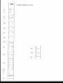
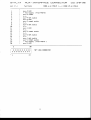
pin nr.:
r{AI
function
NI_CC]NINIEC-TGFt
lH4-f9BA
l
grotrnd
digital
gro.md
digital
- 18 V
(for togic supplies)
(for logic supplies)
+ l8 V
audio grcr-rnd
gro.nd
logic
right
master rnixtuss
logic
h.rss
Ieft
rnaster mixh..rss
solo mixtrJgs
sub I rnixb..rss
+ 18 V
(for audio supply)
sub 7 rnixb-rss
+ V Phantcrne (+4E}\/)
sub 6 mixtuss
audio grcund
sub 5 mixh,.tss
audio ground
sub 4 rnixtusg
audio ground
sub 3 mixtuss
audio grotrnd
sub 2 mixtuss
audio ground
sub I rnixtr,.rss
audio grotnd
aux 4 mixh-rss
audio gromd
aux 3 rnixtx-rss
(optirytal )
Crnix on/of f
aux 2 mixtrlss
cfrassis
earth
aux 1 rnixtuss
- 18 V
(for audio supply)
1
I
3
+
5
6
7
9
LN
11
L2
13
L4
15
L6
L7
1A
1?
m
7L
22
23
24
-)q,
26
27
n
n
w
31
32
-??
34
.>
i,f
ix*
^1
date:
34
xx* x***
**
*xx*
x**x)trf
x*)k*)tl(
**x
t*x
33
TF
VIEt^i COfV\ECTOR
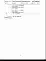
S-TYI_YX
AIJX*f
pin nr.:
I
2
3
4
function
aux-4
+ Vsl
aux-4
n.c.
aux-4
aux-3
aux-S
n.c.
aux-3
n.c.
aux-l
n,c .
aux-Z
n.c.
aux-2
n.c.
aux-1
aux-l
- Vs1
aux-Z
q
A
7
a
9
L@
11
L2
13
L4
lq
16
L7
tE}
L9
m
2
:
NI-fERFACE
LED
anpply
reget
(frorn PCB-S)
set audio
LED
reset
audio
set
audio
LED
reset
set
audio
audio
set audio
reget audio
( f rorn PCB-S
srpply
LED
)
m
)|(f,f***XXX*
date:
LW-Lgffi
CO\N 6 on PCB-S <___> CCI\N fS on PCB-4
l
TF
VIzu COV\ECTM
l*x*t(***x**
^1
CCININIEC-fCIR
1?
.)
Sl-Yl"-\/X
pin
AI"JX-AIJD
functim:
nr.:
1
2
4
q
6
7
I
I
L@
2
l(ft(*{(
I
I
CDIr|NIEC*I-CIF?
CSV\ 25 on rcB-S
grqrnd
aux-4
gro,rnd
aux-3
grumd
aux-2
grannd
aux-1
grcr.nd
+ Vsl
(frorn
shield
( sI ider )
(frorn
shield
( sI ider )
(frorn
shield
( sl ider )
(frorn
shield
( sI ider )
(frorn
shield
( f rorn PCB-S)
TF
VIEW CO\hECTffi
L@
f*xx*i
I
f O
PCB-4)
PCB-4)
rcB*4)
PCB-4)
PCB-4)
date:
LO-W-tqW
s-rYr_YX
[-EF-f-l"lA5-fER
ALJD
CO\N 14 qr
pin nr.:
functian:
1
2
=
4
5
6
7
L-LEDbar send (to PCB-4)
( AdRr)
L-out
trp-track
B right-ingx-rt
(frorn PCB-4)
gro-rnd shield
ttap-track
B left-input
(fran
grcr-nd shield
PCB-4)
tr,.ro-track A right-input
(from PCB-4)
ground shield
ttrp-track
A left-inplt
(frun PCB-4)
ground shield
a
I
L@
2
I
L@
XX*X*
TF
txxx*x
^1
I
VIEI^J CthI\ECTm
I C]
PCB-4
CONINEC-FCIR
date:
LA-@4-1c
functisr;
prn nr.:
'|
+18V
+18V
+ 48 V (pl-nntorne)
earth
C-nix s'r/off
earth
chassis earth
earth
_18V
-1AV
2
3
q
6
7
a
I
LA
LO
{xx#*
**x*x
Cc]fr|r{
CPU*F?EFEF?E[\|CE
S-T-Y[-YX
TCP VIEtrt CmnECTm
ffI\N
S qr
PCB-S
-
date:
t@-54-19B€
-fYt-YX
CH./l"lASl-ER,/
pin nr.:
f NITERFACE
function:
LED (off)
(off)
audio-gw
(LT]U)
earth
switch-status
inverted
IRO
not wired
LED (of f )
(used
not wired
audio sw (off)
(used
not wired
1
2
3
4
5
6
7
a
I
1E
C0t\nl 2@1 sl
local-mode
srly)
for
Iocal*ncde
only)
LA
,ftl(*x*i
I
*
l_
TF
x***
:
9
I Tgr VIEyI PCB*FEADER
i
^1
9
l l
re{rpve
on master
2
* # + + +
S#+++
VIEW CO\I\ECTM
1A-44-1944
CFIQNAEL,CONAImL-m4
for
1A
date;
SFl}lTS
when CPU is
connected
S-TYL-YX
pin nr.:
I_E[)-E}AFt
C0\N 6 on PCB-3,
function:
+18V
ground logic
L-rnaster LEDfeed
R-master LEDfeed
3 LEDfeed
tape return
4 LEDfeed
tape return
7 LEDfeed
tape return
A LEDfeed
tape return
tape return 11 LEDfeed
tape return LZ LEDfeed
tape return 15 LEDfeed
tape return 16 LEDfeed
tape return
1 LEDfeed
2 LEDfeed
tape return
5 LEDfeed
tape return
tape return
6 LEDfeed
I LEDfeed
tape return
tape return L@ LEDfeed
tape return 13 LEDfeed
tape return 14 LEDfeed
1
z
3
4
5
6
7
a
9
LQ
11
L2
t3
I4
15
16
L7
1A
L9
m
n
I
XX**Xf
)***X
i
i*x****fx{*
^1
I
L9
date:
CC]NINIEC'TOR
TCP VIEW CO\NECTM
CS\N I
LA-o4.-L*l€,
on PCB-6,
D-COt{rl chassis
S]-YLYX-r_A
COI\f{ 3
SHr.Jt\-r
AJX1+2
SE-r-r
pre
standard:
optiural
fader
date:
post
fader
I
###oo
i
I
#ooo:
* -----
I
*ooo
i
to*oo:
: pre equalizer
optianal
LWe4-Lgffi
i o#*#0
pre equalizer
:
cov\ 4+5 A-JX3+4 standard:
I Nt(3S
---
*
lo*oo
ioo*o:
pre fader
optional:
i
# ---
ioo*o
CO\N 6
not in use
standard:
C_IYIX
I
*** I
oo I
oo:
#*#
optioral:
in use
( no sl-r-nts
co\I\ 201
optional:
not
not wired
gro,rnd
of pfiase
slt
in phase
FADER CO[$I.
1
2
3
4
use
++
++
I
I
**+
#*+
g
l:
2 S|-tJ\lTS
refllove
I
z
4
2
L@
use
i
i
i
I
i SIDE-VIEI^f PCB-I-€ADER
;
^1
l/.,IT?INIC3
MIC IfWUT
1
2
3
4
coru\ 7
in
CPU in
s-rYt_YX--1_A
coNhl 2
ioo
ioo
ioo
ioo
)
CPU CI-{AIITEL INTERFffi
standard:
i
not wired
tclp
grctnd
sli.der
( XLR)
{
*)
colq.rr
( black )
(green )
(red)
( blue)
(FADER) co1crur
3
I
2
( black )
(green )
(red)
( blue)
ioooo
L234
ioooo
L234
i
ST-YL-YX_24
ctlhl
4
AIJX1+z
sE-r-l-
SHLJr{-r
post fader
optitrral:
optianal:
switchable
pre
standard:
fader
I r\(3s
date:
W3-1948
i#ooo
I
i*ooo
I
:o#oo
I
io#00
i
- * -*---*
--*
ioo*o
* ---
ioo#o
pre equalizer
optiural:
CmN 5
AJX3+4
post fader
standard:
optianal:
switchable
pre
optional:
fader
i
iooo#
-*-_s
iooos
: pre equalizer
C-tlIX
standard;
not
in
i#ooo
i
io#oo
I
io*oo
I
--*
ioo*o
* ---
I
#
use
loo
ioo
| +r#*
( no shrnts
t
I
I
I
I
in use
)
loo
ioo
:0o
ioo
I
i
tooo*
----_--
i **#
optional:
I
i
looos
Co\N 6+7
I
i*ooo
_ * *_---
tooso
optional
i
:1
t.)
tL
ls
i4
t
I
C0\N
8+9
optional:
c0\N 201
optianal:
S-rYt_Yx*24
ct}\ht 2+3
not
in
CPU in
L@
not wired
top
gra.nd
slider
RE}MTE COV\.
I
2
3
4
uge
use
i o##*o
i
I
**
*#
+++
+++
: SIH_VIEW
I
^1
? ii
remove 2 S|-{-I{TS
not wired
break-contact
rnake-contact
P-contact
(FADER) colq-rr
3
1
2
( black )
(green)
(red)
( blue)
(ShJITCH)color
2
4
1
I
2
L{rFqrt\c=
FADERCO[U!.
I
2
3
4
CO\N 1A
-l@ElV
CPU CF*ArTI\EL INTERFACE
standardr
*ls#oo I
: + 4dEil
DIRECT o'JT standard
io
lo
io
:o
(JmK)
( black )
(green)
[sleeve]
(red)
[ring]
(blue)
ttipl
1
2
3
4
ioooo:
PCB_I.€ADER
S-T-YT-YX-34
SHUN-F
I NIC]S
post-fader
T#E
OJT
( 1 sl-unt
CUU!4+?
co\hl 5
TffiE
2ffi4-L98
c0r|-
i ##*oo
(2xlsh-nt)
pre equalizer
optional:
CO\N3+8
date:
c0\ht 2 :
p*JXS+4
standard:
ct}\N2+7
SE-f-r
:
I O#*#0
o#*#o
: oo*##
i
standard:
-1O dEil/
lofl#*o
optional:
+ 4 dBu
i #*#oo
standard:
-10l dEil/
i o*##o
optiulal:
+ 4 dELr
i*+f#oo
)
IN
SL'B6RO.P SELECT
first
i oo**
ioooo
nndule:
i
**( 2 sh,nts
oo**
ioooo
)
secorrd module:
:0000
##oo:
ioooo
##--__
##oo
third
nndule:
loo##
fourth
npdule:
I
t
ioooo
*#oo
toooo
*#
I
CONT\1&F11
C_MIX
standard:
not
in
**00loo00
use
I #**
loo
loo
(2x2sl-unts)
optiaral:
I
I
I
I **#
I
ioo
loo
loo
loo
l1
i2
l3
i4
in use
( no sl-rnts
+
)
i
i
i
CONT\ U1+U2
standard:
in
not
optional:
CPU in
S-IY[-YX-*SA
I
2
3
4
ccl\Al 6
;
: *
i
:
g
reflEve
use
^1
i:
2 S-["NTS
not wired
top
grot-nd
slider
;
1
2
:
:
:
!
:
i
o
o
o
( black )
(green )
(red )
( blue)
I SO-DER-SIDE
(pin
F
,_
13 & 14)
I'€ADER:
CO{rl 6
. * l
L9i
mi
2 i SECS\D l'0DtIE
(pin
5 & 6)
t
r.r|r.
I SCI-DER-SIDE tr
I t
F€ADER: CCI\N 5
r.*.
i1
L9
THIRD MOruE
SO-DER-SIDE F
lQ
r
(pin 15 & 16)
I-€ADER: CO\N 6
1
I
2
F0-RTH l'€D{.j-E
(pin
7 & 8)
t _____-
;
i:x:
SC}-DER*SIDE F
i?
:::*::i
19
optimal
optioral
optirral
optional
i SIDE-VIBI| PCB-FEADER
#*+++
*#+++
(FADER) ccllq-rr
LEDEIffi CO\I\ECTm
Z@pins
;
2 : FIRST l'CIUIE
I
:
use
?
t\r I F? f Nl(=
ct}\Al 12+13 FADER Co\m.
im
LA
CPU CI-{AT$EL INTERFACE
FIFTH f'CIUIE
SIXTH l',IlDtl-E
SE\IENTHIIDLLE
EIGHTH fCI[||'LE
:
:
:
:
pin 17 & 18
pin
I & LA
pin Lq & m
pin 11 & 12
FEADER: CO$rl 6
I
2
3
4
S-TYL*YX_4A
Ctnhl 2
SH(JNI-T
L-tlJT
+4dE}'r
standard:
( I sl-r-nt
SET-TINIGS
date:
1ffi4-1944
o
l#l
i#i
ioi
toi
)
#
*
o
-1O dElV
optioral:
( 1 sfunt
)
z-TRrcK A/B
CG\N 3
( 4 sfr.mts
-18 dEV
standard:
)
#
*
#
#
*
#
ET.-
s
s
AR
BR
o
o
o
H-
o
o
o
o
A-
BR
g
A-
AR
+ 4 dE}'.r
optimal;
( no shrnts )
co\N 12
C-r4IX
not
standard:
( 2 slunts
in use
s#*
oo
oo
*s#
)
oo
oo
oo
oo
I
I
i
i
I
2
3
4
opticnal r in use
( no sl-unts )
U.JI fR I f{G
S-T-YLYX*4A
C0\hl 13
C-MIX O\
cols,rr
I
2
3
4
( black )
(green )
(red)
( blue)
not csrnected
not cmnected
C*MIX on (+12/)
C-I'1IX gro-rnd
Cg\hl 14
LEFT-I'4ASTER AJDIO CCI\N.to
crfv! 15
AJX-INTEIdtACE
ccl\hl 21
FADER CO\N.
1
2
3
4
co$!
22
?4
not wired
top
ground
slider
l0-pin
to
2@-pin
to
2@-pin
fA'pin
cmnector
to
lo
lo
io
io
( black )
(green)
(red)
( blue)
3
I
2
( XLR)
not ulired
ground
qlt
of phase
in phase
AJX AL,DIO
PCB-S
PCB-6
I
2
3
4
(FADER) colour
LEFT C}.JTPUT
I
2
3
4
C$\N
to
o
o
o
o
:1
i2
i3
i4
colo,rr
toi
ioi
:oi
( black )
(green )
( red)
(blue)
;
3
2
PCB-S
l@-pin
6
to
'*:_'
ltl-pin
connector
I
2
3
4
connector
s-rYt_YX-5A
co\hl I
SHLJN{-T-
R-OJT
I NI(=S
+ 4 dElu
standard:
( I sfunt
SE_T--T
date:
o
l#
:#
*
*
io
lo
)
LM4-L9ffi
o
-1O dEV
optional:
( 1 sFunt )
CSN
1A
LEDBAR SELECT gtandard:
( 2 slunts
oo
L/R
oo
oo
s*
*#
**
*#
)
*#
**
oo
su-o
optional:
S0-O
( 2 slunts
)
ffhN
t6
C_MIX
standard:
not
in
uEe
oo
oo
oo
oo
+FS*
( 2 sl-nnts
oo
oo
)
**#
optional:
in
( no sfr-nts
I.,{IRINIC3
S-TYL_YX_64
CSf!
U
1
2
3
4
co\t{ 11
Llf{!
la
19
colo-rr
FADER Cg\N.
not wired
top
ground
slider
RIGI-IT OJT
I
2
3
4
not wired
gro-nd
cut of phase
in pluse
oi4
013
oi2
oi1
( blue)
( red)
(green)
( black )
2
3
I
TA-KBffiK input
gro-nd
gro-rnd
not wired
LEFT-+IASTER AJDIO CONN.to
1
2
3
4
cil\t\
( XLR)
TA-KBffiK
PCB*4
l0-pin
to
l@-pin
(FADER) colcr-rr
;
1
2
( black )
(green)
(red )
( blue)
o i1
o i2
o i3
_:_
i4
( X L R ) colour
;
3
2
( black )
(green )
(red)
( blue)
lo
lo
lo
io
rt
rl
i2
is
i4
cstnector
1
2
3
4
use
)
product
safety
Thlr producl lr manufaclured wl0t lho hlghed
rlendardr and lt doublo checlcd In our
quallty conlrol dopartmonl for rellabll$l In the
'HIGH VOLTAGE' tocllon.
GAUTTOII
. Never lemove any panels, 0I open lhis
equipmenl.No user servicableparts inside'
. Equiprnent power supply musl be grounded
al all limes.
OnlV use lhis product as described, in
user manual ot brochure.
. Do nol operale this equipment in hieh
hurnldity or expose it to waler or other liquids.
. Chech the AC power supply cableio assure
secute conlacl.
. Have your equipment checked yearly by a
qualified dealet service cenler'
. Hazardous electrical shoch can be avoided
by carefully following the above rules.
.
EXTRA CAUTION
FOB LIVE_SOI'I{D
Ground all equipment using the ground pin
in lhe AC povltel supply cable' Never remove
this pin. Ground loops should be eliminated only
by use of isolation transformers for all inpuls
and oulputs. Replace any blown f use with the
same type and rating only afler equipmenl has
been disconnecled from AC power. lf problem
scrvicl
persists, reluln equipmenl l0 qrelif lld
tcclriciel.
Pleare
carefulltl
road lhe followlg
tlrngl
fhrirt
crrrcrl
errrrl
rf
llc
e perrrr.L
person can feel a shock because the
A
muscles in a body respond lo electrical currenl
and because the heart is a rnuscle it can af'
fecl, when the currenl is high enough. Currenl
can also be f atal when il causes lhe chesl
muscles to conllact and stop breathing.
At what potential is currenl dangereous,Well
the f irst f eeling of currenl is a tingle al 0,001
Amp of currenl. The current belween 0.I Amp
and 0,2 Amp is fatal
Imagine that your home f uses of 20 Amp
can handle 200 limes more currenl than is necesHow does resistance aflecl lhe
sary lo Lilt
person
a
feels. Atypical resislance between
shocl
one hand to the other in "dry" condition could
lrG Phtirg
well ovel 100,000 Ohm. If tn
prfrsair parsplrirg
brdy
slrga t.rr
.l
il
hvcrad
yerr
brdy
rrtislerca
fy erd
5OZ- TLis
lr e silrrlirr
tler
l.rc
by
Current
fbwcrl
ee:ily
rlicl
crrrerl
ir
wilt f low when lhere is a dif ference in ground
potential belween equipment 0n slage and in the
P.A. system.
Please do check if there is any polential be'
ihe miles and lhe
lween the housing of
guitarlsynlh amps, which will be linked by your
body on stage. lmagine, a guitar in your hand
and ysur lips close to the mike! A ground polen'
tial difference ol above l0 volls is nol unusual,
in improperly wired buildings it can possibly be
as high as 24O volls. Allthough removing lhe
ground wire sometimes cures a system hum, il
will creale a vety hazardeous silualion f ot lhe
performing rnusician,
bY
aguiPnert
ell
certl
Alvey:
Y.rr
grnrdirg
pir
rlirr
ir
llc
Phg.
tt.tr
bY
crrad
ba
trly
lmpr
slnld
Hrr
irprtfrrlprt
istletiu
prrpcr
erd
virirg
trurlrrn:rtReplace f uses always with the same type and
raling after lhe equipment has been lurned off
and unplugged. If the f use blows again you
have an equipment f ailure, do not use it again
and relurn it to your dealer for repair'
lnformatlon
Especially in sound equipment 0n slage the
f llowing information is essential to know. An
eleclrical shock is caused by voltage and currenl,
actually it is the current that causes the shock.
ln practise the higher the voltage the higher the
currenl will be and the higher the shock.
Bul there is another thing l0 consider and il
is resistance. W hen the resislance (in Ohms) is
high beiween lwo poles, lhe current will be
low and vica versa.
AII three of these; voltage, curlent, and resis'
effect
lance are imporlant in determining the
tlc
eavcrily
of an electrical shocl. IltvaYGt,
by
prirtrily
detcrrrirsd
ir
rf
e shcl
lasl but nol least Be carefull nol t0
And
touch a person being shocked as you, youtself
could also be shocked. Once removed from lhe
shock, have someone send f or medical help in'
rnediately.
Always keep the above
mentioned information in mind
when u$ing electricallY
ponrered equipment-