1
BBL.2 USER’S MANUAL
by
N.-P. Chen, C.-C. Chen, C.-P. Hsu, H.H. Chen,
E. S. Kuh, and M. Marek-Sadowska
Memorandum No. UCB/ERL MS5/2
24 January 1985
BBL.2 USER'S MANUAL
by
N.-P.
Chen, C.-C.
Chen, C.-P.
Hsu, H. H. Chen,
E. S. Kuh, and M. Marek-Sadowska
Memorandum No. UCB/ERL M85/2
24 January 1985
ELECTRONLCS RESEARCH LABORATORY
C o l l e g e of E n g i n e e r i n g
U n i v e r s i t y of C a l i f o r n i a , Berkeley
94720
BBL.2 User35 Manual
Nang-Ping Chen, Chao-Chiang Chen
Chi-Ping Hau, Howard H. Chen
Ernest S.Kuh, and M. Marek-Sadowaka
Department of Electrical Engineering and Computer Sciences
and the Electronics Research Laboratory
University of California, Berkeley, CA 94720
I
1
I
I
ABSTRACT
bal route. In detailed routing, channel router and switch-box router are used to
I
BBL.2 User’s M a n d
Nang-Ping Chen, Chao-Chiang Chen
Chi-Ping Hsu,Howard H. Chen
Ernest S. Kuh, and M. Marek-Sadowska
Department of Electrical Engineering and Computer Sciences
and tbe Electronics Research Laboratory
University of California, Berkeley, CA 94720
1. What is BBL ?
I
4
BBL is an abbreviation for the Berkeley Building-Block Layout S stem. It
can be used as an automatic tool to generate the layout of integratedl circuits.
The design style of building-block layout has the following features:
(1) It uses library cells or user-designed macros as the building-block mddules.
(2) Each module may have terminals along its boundary.
b
(3) All the terminals with the same net name should be connected toget er.
(4) The objective of the placement and routing is to minimize the layout area.
(5) 100% routing completion can always be achieved.
design. It can also be applied in a hierarchical design where BBL is used as the
layout tool on each level.
2. What can BBL do ?
,
Each module may have terminals on its boundary. Terminals with khe same
net name are to be connected together. While the positions for terminals
along the chip boundary can be shifted according to the size of
their relative positions will not be changed. All other terminals ar
the boundary of their parent modules.
I
~
All the modules are treated as blockages. No wires are allowed to cross the
modules.
Pre-placement is not allowed in the BBL placement system. Howe er, since
the output of the placement is a routing textfile, the placement sy tem and
routing system can be used separately. That is, the coordinates
04 modules
can be specified by the user without using the the completely +tomatic
placement system. Modules should not overlap each other, and all(the bot-
I
tom level modules must be inside the boundary of the top level mod le.
Two layers are available for interconnection.
I
Four design-rule parameters should be specified; namely, horizontal vertical)
track spacing, and horizontal (vertical) edge clearance.
I
The current version of BBL does not allow any prewiring b fore the
automatic routing process. However, interactive routing and wire mo
can be done after automatic routing.
1
3. The placement system of BBL
The placement system of BBL is called PARADE. It consists of th ee major
phases: the bottom-up phase, the top-down phase, and the tradeoff phas
The bottom-up phase starts with the module-wise
Based on this result, the pairing process is activated to
modules. The pairing process continues until some
that is, when connectivity is no longer considered
cess is a set of clusters, modulepain, and single
nected modulepair, a set of potentially good
information will be used in the next step,
~
.
objective is to arrange the modules of each cluster or module-pair to form supermodules which optimize the usage of space and the distance of connecticns. During this step, pins of different modules are aligned, relative positio1.s of the
modules in each cluster are determined, and wiring areas are allocated for both
the local nets and global nets. The supermodules can be of any rectilinear shape,
The goal of the tradeoff phase is to assign "blocks" properly in th$ generalized row structure such that the dissected modules are restored, and tbe global
I
connection lengths are minimized. This phase begins with an initial arr ngement
where rows of cells are placed and all the constraints are satisfied. The dissected
blocks are restored in the initial arrangement. Then, an iterative
activated to do the global paths assignment and the detail placement.
rocess is
he spac-
ings between blocks are determined and the difference of the row lengtljs is kept
i
as small as possible by using pair-wise swappings. Finally, the horizon a1 global
tracks are assigned and the rows are vertically compacted.
After all the internal modules are placed, we start to place the 1/0 ads subject to the sequence constraints specified in the placement textfile. The 1/0 pads
are free to be placed anywhere; however, their sequence on the bound ry of the
chip must obey the given constraints. This placement system is c mpletely
automatic and pre-placement is not allowed. However, the user may c ange the
coordinates of the modules afterwards by editing the routing textfile.
~
I
4. The routing system of BBL
The routing system of BBL is called ROSE. It can be divided
parts:
prerouting analysis, global routing, and detailed routing.
1t
to three
'
he new
.
features of this routing system are power/ground routing and bus routin
At the beginning of routing process, a set of "bottlenecks" is
enerated.
Bottleneck is defined as a region between the parallel edges of two ne ghboring
modules.
It is a critical region where congestion is most likely
o occur.
Id
Bottlenecks are very important for the whole routing system. As mo ules are
shifted, the structure of some bottlenecks will be changed.
II
larger than the expected density. Modules are then shifted to allocate the routing space.
The next step is global routing. The purpose of global routing is to assign
each net a wiring path without actually embedding it. A global routing graph is
generated by representing each bottleneck by an edge. The weight for each edge
is defined as follows :
edge weight = A
* L + B / C N+
1
1
where L is the length of the active bottleneck region, N is the numbe of available tracks, and A,B,C are the parameters specified by the user. If
shortest
path is desired, the length factor "A" should be large to dominate the edge
weight. If the chip area and routing congestion are of primary con ern, the
congestion factors "B" and "C" should be large to avoid allocating ex ra space.
According to our experiences, a combination of A=l, B=50, and C=
give the best result.
A Steiner-Tree-On-Graph algorithm is then applied on the glob
tends to
routing
graph to find the minimum weighted tree which connects all the terminals in a
net. The net ordering is determined by the available routing space. The net
1.
with less routing space will be routed first. For those nets which be ng to a
common bus, they will be assigned the same global route. After all the qets have
been assigned their routes, we get a better estimation of the routibg space
needed. The required number of tracks in each bottleneck is equal tolits maximum routing density, and a compaction process will be done to rernoJe redundant routing space. After the compaction, the minimum chip size is obdained by
the global router, though it might be increased later in detailed routing. 1
Two detailed routers are used in BBL. One is the channel router, and the
other is the switch-box router. The channel router is suitable for the routing
(h
problem in a rectangular region with fixed terminals on two opposite e ges and
floating terminals on the other two edges. The switch-box router, on he other
hand, can handle any rectilinear region with fixed or floating terminals. 'It is not
I
as efficient as the channel router, but it is more flexible. In BBL, t e active
region of a bottleneck is routed by the channel router, and all other re 'on9 are
routed by the switch-box router.
I
Power/ground nets are given higher priorities during the routing pr cess. In
global routing, the wire widths for power/ground nets will be calcula ed after
their global routes are found. In detailed routing, the channel router an switchbox router use preprocessors to route the power/ground nets on one layer if
J
possible, and postprocessors to make jumpers for those signal wires w ich cross
the power/ground nets.
1
+
Both the channel router and the switch-box router will return a r quest for
extra space if the given routing area is not sufficient. Some modules wi then be
shifted to allocate additional space for routing. A 100% routing complktion can
thus be guaranteed, while the increase in chip size is kept as small as
PO
ible.
I
I
5 , How do you enter input data ?
6.1. A placement input textfile
The input format of PARADE is very similar to that of
li
ROSE. T e details
can be found in Appendix B.
~
I
5.2. A net-list routing input textfile
This is the standard input for ROSE. It includes the description of modules,
Two levels of modules are used. The top-level module, which enkloses all
the modules on the bottom level, is usually the chip boundary. The bot om-level
modules, which are treated as blockages, are regular modules.
A terminal must be on the boundary of a module. For terminals on the chip
boundary (usually 1/0 pads), their positions will be moved proportion lly when
~
the chip boundary changes during the routing process. Every terminal
4
ust have
a routing direction, which should point toward the routing region. Powe /ground
terminals may have different widths. The width of the source terminal hould be
equal to the sum of the widths of sink terminals. If the power termin 1 is on a
horizontal edge, the width will grow leftward. If the terminal is on
vertical
edge, the width will grow downward. The distance between the powe /ground
~
terminal and its neighboring terminal (or the corner of its parent modul
be enough to cover the wire width and the design rule spacing.
Four parameters of the design rules should be specified. The h
(vertical) track spacing is the minimum spacing required between two h
lines. The horizontal (vertical) edge clearance is the minimum distance required
between a horizontal wire and a horizontal boundary segment. Currently all the
design rule parameters must be set as 1, so all the coordinates should be scaled
down (i.e., divided by the track pitch) before they are used as the input.
A detailed description of the input format is in Appendix C. Theoretically,
there is no limit on the number of modules and terminals. However, t o make
5.3. A CIF input file
The user can enter the input data by using the interactive grapwcs editor
KIC. In fact, any graphics editor will do as long as the CIF' file genemted contains the following layers:
- symbolic layer for terminals
BNDl - symbolic layer for the chip boundary
BND2 - symbolic layer for modules
TRM
The chip boundary is a rectangular box which contains all the mddules. A
module is represented by a box or a rectilinear polygon, and ternjinals are
represented by boxes. The center of a terminal box must be on the bobndary of
its parent module. Each terminal has a label, and the lower left corner iof a label
should be inside the terminal box. The spacing between the center of [terminals
and between the center of a terminal and the corner of its parent moddle should
be equal to multiples of the minimum track spacing.
I
The CIF input file can be transformed into the standard ROSE inplt format
by using the CIFZROSE command. The new file generated will then b& the netlist input file for ROSE.
I
6. What is the output of BBL f
i
The output generated by PARADE is a routing input textfile. T e coordinates of the modules are specified. The locations of the terminals are pdated if
rotations and/or reflections are performed on the parent module. Thc size and
the shape of the boundary of the top level module are modified. The I/C pads are
reassigned subject to the sequence constraints specified in the placem !nt input
tex tfile. The spacings between 1/0 pads are calculated proportional y to the
spacings given by the input.
The routing pattern generated by ROSE is written into a data bm ! textfile,
whose name is specified by the user at the beginning of the program. T le format
of this output file is described in detail in Appendix D. The user can 1( ~ l as t the
final placement and routing by using the LOOKDB command. A CI ' file can
also be generated by the CIF'GEN command. Then the interactive gra bhics editor KIC can be incorporated to do the interactive routing or modi& ntion. A
final plot can be obtained by using the CIFPLOT. ( Both KIC and
are in the Berkeley VLSI Tools package. )
7. Appendix
7.1. Appendix A : Commands and application programs
7.2. Appendix B : Input format for BBL placement
7.3. Appendix C :Input format for BBL routing
7.4. Appendix D : Output format for BBL database
(
IFPLOT
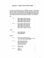
Appendiz A :Commands and Application Programs
Contents
lookdb(1)
- CIF format generator for BBL
- translate C" format to ROSE format
- database look or dump program
parade(1)
- automatic placement system for EBL
rose( 1)
- automatic routing system for BBL
cifgen( 1)
cif2rose(l)
rose2parade(l) - translate ROSE format to PARADE forma
BBL System’s Manual
CIF’GEN( 1 )
C@GEN( 9 )
NAME
cifgen - generate a CIF file from BBL database
SYNOPSIS
cifgen [ -option [ -option ]
... ] input-file
output-file
DESCRIPTION
Cifgen is a CIF format generator for BBL. It takes BBL database as he input
and outputs a CIF file. The actual size of layout is controlled by inpu parame
ters. The result can be examined by an interactive graphics editor Atic I] or the
CIF’plotter cifplot [2]. The options are:
-h (HPterminal)
Display a layout on the HP2648A terminal.
-d (defaults)
Allow you to change default values of geometrical paramete1 interactively during the program execution. Default values in CIF unj 3 are:
1. metal segment width = 300
2. poly segment width = 200
3. contact size = 400
4. terminal size = 400
5 . metal to metal separation = 300
6. poly to poly separation = 200
-c (chip)
Generate the whole chip.
-m (module) module-name
Generate the specified module only.
-n (number) maz-depth
Specify how many levels in the hierarchy are to be translate( into the
CIF file.
-I (input) teztfile
Input data from teztfiIe
name of input-file.
.A
database file will also be created with the
A typical command of using cifgen to generate the layout for the whole hip from
our text example test.db is cifgen -c -n 2 test.db t e s t i f ”.
FILES
BBL/ROSE/CIF
2nd Edition
/*
1/11/85
1
CIF'2ROSE ( 1 )
BBL System's Manual
P
cIF2 OSE(1)
NAME
cif2rose - translate a CIF file into the ROSE input format
I
SYNOPSIS
I
ciflrose input.cif input.rose
I
DESCRIPTION
Cif,"roue is an input interface between CIF format and BBL fatmat.
generate the net list ( a standard input format for ROSE ), the
must include the following layer definitions:
TRM : symbolic layer for terminal definition
BNDl : symbolic layer for chip boundary
BND2 : symbolic layer for regular module frame
To define a routing problem, the modules and terminals should be splecified
follows :
;ts
1.
Chip boundary is represented by a rectangular box.
2.
Regular modules are represented by boxes or rectilinear polygons.
3.
Terminals are represented by boxes on the TRM layer. The cebter of a
terminal box must be on the boundary of a regular module.
4.
Terminal labels are specified on the TRM layer. The lower left c4rner of a
label must be inside its associated terminal box.
FILES
BBL /ROSE/CIF/*
SEE ALSO
Berkeley VLSI Tools
KIC (cad)(l]
CKFPLOT (cad)[2]
BUGS
This program generates the old input format for ROSE. Modifications 1 must be
made to generate informations for pcwer/ground routing and bus routind.
2nd Edition
1/11/85
LOOKDB( 1 )
BBL System’s Manual
LO( KDB( 1 )
NAME
lookdb - database display routine for BBL
S YN O P SI3
lookdb filename
DESCRIPTION
This program displays all the database information on an HP2648 term ial. The
manual for usage can be printed by typing the HELP command. Curr ntly, the
following commands are supported by lookdb:
h : help
q : quit
p : change plot flag
n : change print flag
? : print all the signal and module names
s : identify the specified signal
m : identify the specified module
d : display regular modules
dw : display regular modules with default window
da : display chip routing
daw : display chip routing with default window
x : find the name of a module by cursor
xr : find the name of a routing module by cursor
xm : find the name of a regular module by cursor
R : run channel router in the specified routing module
R2 : run 2D router in the specified routing module
W : define new window
f : find input file name
r : read input file
w : write output file
! : escape
FILES
BBL/ROSE/LOOE;DB/*
BUGS
For display on terminals other than hp2548a, you
BBL/ROSE/LB/display.c with your own graphics program.
2nd Edition
I/ 11/35
must
replace
1
BBL System's Manual
PARADE ( 1 )
NAME
parade - automatic placement system for BBL (Building Block Layout)
SYNOPSIS
parade
DESCRIPTION
i
Parade is the placement system for BBL[l]. It is a completely automat'c process.
No preplacement is allowed. The modules are restricted to be rectan ular and
free t o rotate and reflect in any orientation as long as the edges are ertical or
horizontal. The objective of the placement is to place and orient the odules in
an optimal way such that the final layout area, including the interc nnection
area, is minimized. The boundary of the top level module is determine after all
the bottom level modules are placed and the wiring area allocated. The 1/0 pads
are assigned on the boundary subject to the sequence constraints speci ed in the
placement input textfile. The spacings between the 110 pads are calcu ated proportionally to the spacings given in the input file.
The system will interactively ask user the following questions:
parade
ENTER THE INPUT PLACEMENT TEXTFEE NAME : <filel>
ENTER THE OUTPUT ROUTING TEXTFILE NAME : <file2>
WHOLE CHIP PLOT ? < y / n >
1'
where file1 is the input placement textfile whose format is described inlappendix
I
B. ,and file2 is the output routing textfile for ROSE.
DIAGNOSTICS
A new program which can handle rectilinear modules is under develodment. It
will be provided in our next version of BBL-PARADE.
SEE ALSO
(I]
2nd Edition
I
Chen, C. C.; Kuh, E.S., "Automatic Placement for Building Block Layl
out", Proc. ICCAD, 1984, pp. 90-92.
1/11/85
1
ROSE( 1 )
BBE System’s Manual
B :OSE( B p
NAME
rose - automatic BBL routing system
SYNOPSIS
rose
DESCRIPTION
Rose is the automatic routing system for BBL[l,2]. In the process of ro Iting, the
system may shift functional blocks and compact the layout to achieve 1( 0% routing completion. The terminal positions should be fixed on the bour daries of
functional blocks. The 1/0pads are represented by the terminals on he boundary of the bounding box. The bounding box may be shrunk or enlarg :d in size
so that it will become the smallest rectangle which encloses all the i unctional
blocks and interconnections. Although the positions of these 1/0 pad I may be
changed after the routing, the ratio of the distances between pads wil be kept
the same. The design rules of wire-to-wire separations, wire-to-edge ( lear ances
are specified in multiples of the unit width. Since no additional restricti In will be
put on the contact-to-contact separation, the user is responsible to SI ecify the
wire-to-wire separation large enough to take care of this situation.
This routing system can handle convex rectilinear blocks with arbitr: ry shape
and sizes. No over-the-block routing is allowed. Currently, the systeu assumes
that two layers are available for routing.
A prerouting analysis is equipped with this system. The purpose of thi! prerouting analysis is to allocate routing space for a given placement based on a simple
uniform probabilistic model. The prerouting analysis is not needed f a good
manual placement or automatic placement has been done, but it will be helpful if
the original placement is not good. The user also has to specify three p( ,rameters
which control the global routing. If the user is happy with the place! nent and
does not want to change it drastically, then a large congestion factor B or placernent adjustability f a c t o r C should be used. If the user cares more about the shortest length connections for all nets, then a large length factor A should be used.
The system will interactively ask user the following questions:
rose
Enter input file name : <filel>
Enter output database file name : <file2>
Enter length factor for bottlenecks : (default=l)
Enter congestion factor for bottlenecks : (default=50)
Enter placement adjustability factor : (default=2)
Prerouting analysis ? (y/n)
Compaction after global routing ? (y/n)
Final plotting ? (y/n)
2nd Edition
1/11/85
1
I
ROSE( 1)
BBE System's Xvianual
I
The system will generate a file named "debug" under the same direct ry. This
file contains all the bottleneck information for debugging purpose. F i e 1 is the
input file whose format is described in appendix C. File2 is the outp t of the
database which can be seen by using "lookdb", or generate the CIF fil by using
"cifgen".
er
I
4
SEE ALSO
[l]
Chen, N. P., "The Routing System for Building Block Layou ", Ph.D.
thesis, U. C. Berkeley, 1983.
[2]
Chen, N. P.; Hsu, C. P.;Kuh, E. S., "The Berkeley Building-Blo Layout
System for VLSI Design",Proc. International Conference on
SI, Nosway, August 1983, pp. 37-44.
I
[3]
Chen, N. P.; "New Algorithms for Steiner Tree on Graphs", Pdoc. IEEE
ISCAS, 1983, pp. 1217-1219.
I
[4]
Hsu, C. P., "A New Two-Dimensional Routing Algorithm", Pkoc. 19th
Design Automation Conference, June, 1982, pp. 46-50.
[5]
Yoshimura, T.; Kuh, E. S., "Efficient Algorithms for Channel houting",
IEEE Transaction on Computer-Aided Design of Integrated Cir uits and
Systems, January, 1982, pp. 25-35.
1:
BUGS
k
An early version of this program was sent to several cooperating compa ies, who
tried our program and gave us feedback. We fixed some bugs and in addition,
added new features in this present version, but by no means will this pr gram be
perfect. We continue to welcome comments and will improve it in the f ture versions of BBL.
I
??d Edition
I/ 11/85
2
ROSE2PARADE ( 1 )
BBL System’s Manual
NAME
rose2parade - convert from ROSE format to PARADE format
SYNOPSIS
rose2p arade
DESCRIPTION
RaseZparade will interactively ask the user to enter the PARADE inpul file to be
generated and the ROSE input file to be translated. This program is implemented to help those who already had their own placement and would ke to try
the new BBL placement for comparison.
FILES
BBL /PARADE/rose2parade
2nd Edition
1/11/85
1
Appendiz B :Inplrt Format for BBL Placement
(1) The input text file format
<Date>
BBL PLACEMENT TEXTFILE
e # of modules > modules
< # of nets > nets
{top-level module data}
$
{module data at this level}
$
(2) The format of module data
MOD
/*top level module*/
00
/*origin coordinates*/
<module name>
/*up to 20 characters*/
<module type>
/*the type of module*/
<dimIX] > <dim[YJ > /*the dimension of the module*/
$4
T
/*terminals*/
/*number of terminals on the module*/
< y > <net> <edge> <type> <layer> <width> <depth> <p/q>
< # of terminals >
<x>
/*
* (x,y) - terminal coordinates relative to the bottom-left corner
*
of the module;
* net -- name of the net, up to 2O.characters;
* edge -- the edge of the module on which the terminal locates;
*
i.e. bottom 1, right 2, top 3, left 4;
* type - l(fixed), 2(edge fixed), 3(floating);
* layer - the wiring layer that the terminal resides;
* width - the physical width of the terminal;
* depth - the depth of the terminal toward the inside
*
of the module boundary;
* P/g - the power and ground flag;
* bus - the bus Bag (see also App.C);
*/
<bus>
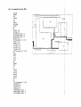
(3) A sample input flle for placement
DATE
BBL PLACEMENT TEXTFILE
8 modules
38 nets
MOD
00
bound
0
330 230
$
T
24
0 160 N 1 4 2 1 1.00 1.00 0 0
0 140 N2 4 2 1 1.00 1.00 0 0
0 1 3 0 N 3 4 2 1 1.00 1.0000
O l 1 0 N 4 4 2 1 1.00 1.0000
0 1 0 0 N 5 4 2 1 1.00 1.0000
O 3 0 N 6 4 2 1 1.00 1.0000
400 N7 1 2 1 1.00 1.00 0 0
70 0 N8 1 2 1 1.00 1.00 0 0
90 0 N9 1 2 1 1.00 1.00 0 0
140 0 N10 1 2 1 1.00 1.00 0 0
1800 N11 1 2 1 1.00 1.0000
210 0 N12 1 2 1 1.00 1.00 0 0
3 3 0 8 0 N 1 3 2 2 1 1.00 1.0000
330 130 N14 2 2 1 1.00 1.00 0 0
330 190 N15 2 2 1 1.00 1.00 0 0
270 230 N16 3 2 1 1.00 1.000 0
240 230 N17 3 2 1 1.00 1.00 0 0
200 230 N18 3 2 1 1.00 1.00 0 0
180 230 N19 3 2 1 1.00 1.00 0 0
160230N20321 1.00 1.0000
120 230 N 2 1 3 2 1 1.00 1.00 0 0
90 230 N22 3 2 1 1.00 1.00 0 0
6 0 2 3 0 N P 3 2 1 1.00 1.0000
30 230 N24 3 2 1 1.00 1.00 0 0
t
MOD
00
ONE
0
80 70
$
T
13
40ON26111 1.00 1.0000
6 0 O N 2 8 1 1 1 1.00 1.0000
7 0 O N B 1 1 1 1.00 1.0000
8030 N18 2 1 1 1.00 1.00 0 0
80 50 N30 2 1 1 1.00 1.00 0 0
5070 N213 1 1 1.00 1.0000
40 70 N23 3 1 1 1.00 1.00 0 0
ONE
e
,
I
*
j /
t
I
,
L
-
I
___.I_
f1
--y
I
d
It
'1; '
j'
I .
FIVE
1
1
1
c
-4
-
\ I
1
'
I.
i
i
i
I
E I GHT
30 70 N22 3 1 1 1.00 1.00 0 0
20 70 N24 3 1 1 1.00 1.00 0 0
0 60 N4 4 1 1 1.00 1.00 0 0
0 40 N5 4 1 1 1.00 1.0000
0 20 N2 4 1 1 1.00 1.00 0 0
0 10 N3 4 1 1 1.00 1.000 0
$
MOD
00
TWO
0
70 40
$
T
6
50 0 N30 11 1 1.00 1.00 0 0
70 10 N17 2 1 1 1.00 1.00 0 0
7020N37 2 1 1 1.00 1.0000
40 40 N20 3 1 1 1.00 1.00 0 0
30 40 N19 3 1 1 1.00 1.00 0 0
20 40 N18 3 1 1 1.00 1.00 0 0
$
MOD
00
THREE
0
40 30
$
T
5
10 0 N17 1 1 1
20 0 N16 1 1 1
30 0 N38 1 1 1
0 20 N18 4 1 1
0 10 N37 4 1 1
$
MOD
00
FOUR
0
100 20
$
1.00
1.00
1.00
1.00
1.00
1.00 0 0
1.00 0 0
1.00 0 0
1.0000
1.00 0 0
T
7
40 0 N27 1 1 1 1.00 1.00 0 0
60 0 N33 1 1 1 1.00 1.00 0 0
70 0 N32 1 1 1 1.00 1.00 0 0
80 0 N35 1 1 1 1.00 1.00 0 0
90 0 N34 1 1 1 1.00 1.00 0 0
60 20 N25 3 1 1 1.00 1.00 0 0
10 20 N30 3 1 1 1.00 1.00 0 0
$
MOD
00
FlVE
1
0
80 40
$
T
10
200 N6 1 1 1 1.00 1.00 0 0
3 0 0 N8 1 1 1 1.00 1.00 0 0
60 0 N29 1 1 1 1.00 1.00 0 0
80 20 N11 2 1 1 1.00 1.00 0 0
60 40 N27 3 1 1 1.00 1.00 0 0
40 40 N26 3 1 1 1.00 1.00 0 0
20 40 N25 3 1 1 1.00 1.00 0 0
10 40 N5 3 1 1 1.00 1.00 0 0
0 3 0 N 1 4 1 . 1 1.00 1.0000
0 10 N7 4 1 1 1.00 1.0000
$
MOD
00
SIX
0
30 50
$
T
4
10 0 N10 1 1 1 1.00 1.00 0 0
30 20 N31 2 1 1 1.00 1.00 0 0
20 50 N27 3 1 1 1.00 1.00 0 0
0 40 N29 4 1 1 1.00 1.00 0 0
$
MOD
00
SEVEN
0
50 30
t
T
a
20 0 N9 1 1 1 1.00 1.00 0 0
40 0 N12 1 1 1 1.00 1.00 0 0
50 10 N36 2 1 1 1.00 1.00 0 0
40 30 N35 3 1 1 1.00 1.00 0 0
30 30 N34 3 1 1 1.00 1.00 0 0
20 30 N33 3 1 1 1.00 1.00 0 0
10 30 N32 3 1 1 1.00 1.00 0 0
0 20 N31 4 1 1 1.00 1.00 0 0
t
MOD
00
EIGHT
0
40 130
$
T
10
20 0 N12 1 1 1 1.00 1.00 0 0
40 50 N13 2 1 1 1.00 1.00 0 0
40 80 N14 2 1 1 1.00 1.00 0 0
40 110 N15 2 1 1 1.00 1.00 0 0
30 130 N38 3 1 1 1.00 1.00 0 0
20 130 N37 3 1 1 1.00 1.00 0 0
0 120 N37 4 1 1 1.00 1.00 0 0
0 110 N30 4 1 1 1.00 1.00 0 0
0 30 N28 4 1 1 1.00 1.00 0 0
0 20 N36 4 1 1 1.00 1.00 0 0
$
$
(4) Restrictions on input data
The current version of
BBL placement has the following restrictions on input data :
* The top level module must be rectangular.
* The bottom
level modules are rectangular functional blocks.
* Module type is always 0 (regular).
* The "type"
of the terminals on top level module is 2 (edge fixed).
The "type" of the terminals on bottom level modules is 1 (fixed).
* The "layer"
and "depth" of the terminals are set to 1.
* The "width"
and "depth" of the terminals are floating number.
* The module and terminal coordinates should be integers.
.*
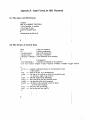
Appendu C :Inpart Format for BBL Routing
(1) The input text file format
SN <number of nets>
{top level module data}
{design rules}
$
{module data at this level}
(2) The format of module data
MOD
<x>
<y>
<module name>
<module type>
<xl> <yl>
<x2>
. .
/*top level module*/
/*origin coordinates, all module coordinates are
relative to this position*/
/*up to 8 characters*/
/*l=routing module; 0 otherwise*/
/*corner coordinates of the module in the
counterclockwise direction*/
<y2>
$
T
<x>
/*terminals*/
< y > <name> <dir> <type> <p/g>
<width>
<bus>
/*(x,y) : terminal coordinates relative to the origin*/
/*name of net is restricted to 6 characters*/
/*routing direction : left 0, down 1, right 2, up 3*/
/*terminal type : 2(fixed), other types are for internal use only*/
/*power/ground tlag : l=power/ground, O=othenvise*/
/*power/ground width : meaningless if power/ground flag=O*/
/*bus number : nets with the same bus number will be assigned the same
global route*/
/*The specifications of <p/g>,<width>, and <bus> are optional*/
$
(3) The design rule format
DES
ht
vt
he
ve
$
<horizontal track spacing>
<vertical track spacing>
<horizontal edge clearance>
<vertical edge clearance>
/* Currently, all the parameters must be 1 */
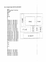
(4)
A sample input flle
SN 29
MOD
00
bound
0
00
loo 0
100 100
0 100
s
T
2 0 0 ~ 3 2
400g32
50 0 busl 3 2 0 1 1
55 0 bus2 3 2 0 1 1
60 0 bus3 3 2 0 1 1
900k32
0 40 ground 2 2 1 4.0
0 7 5 ~ 2 2
090022
10 100 x 1 2
25 100 j 1 2
50 100 s 1 2
75 100 x 1 2
100 45 power 0 2 1 4.0
t
DES
ht 1
vt 1
he 1
ve 1
t
MOD
00
a
0
10 85
10 10
50 10
50 50
20 50
20 85
$
T
10 15 ground 0 2 1 1.0
10 35 p 0 2
10 40 p 0 2
10 45 0 0 2
1050aO2
10 64 busl 0 2 0 1 1
10 67 bus2 0 2 0 1 1
10 70 bus3 0 2 0 1 1
a
1
1
I
-'
ground
'\
- I---
10 80 s 0 2
15 10 z 1 2
20 10 b 1 2
30 10 p 1 2
35 10 r 1 2
45 10 w 1 2
49 10 v 1 2
50 15 g 2 2
50 20 I 2 2
50 30 b 2 2
50 35 a 2 2
50 40 d 2 2
50 45 e 2 2
25 50 m 3 2
30 50 I 3 2
35 50 n 3 2
40 50 t 3 2
20 55 n 2 2
2065y 2 2
20 70 x 2 2
20 80 w 2 2
15 85 x 3 2
t
MOD
00
b
0
65 90
30 90
30 65
65 65
$
T
40 90 bus1 3 2 0 1 1
45 90 bus2 3 2 0 1 1
50 90 bus3 3 2 0 1 1
60 90 1 3 2
30 70 i 0 2
30 80 ground 0 2 1 1.0
35 65 u 1 2
45 65 x 1 2
50 65 j 1 2
60 65 power 1 2 1 1.0
65 70 g 2 2
65 75 y 2 2
65 80 k 2 2
65 85 j 2 2
$
MOD
00
C
0
75 45
90 45
90 80
!
75 80
$
T
80 45 power 1 2 1 1.0
90 50 I 2 2
90 60 x 2 2
90 75 d 2 2
76 80 c 3 2
80 80 b 3 2
85 80 ground 3 2 1 1.0
89 80 t 3 2
75 55 g 0 2
75 65 i 0 2
75 75 r 0 2
a
MOD
00
d
0
85 15
85 35
60 35
60 15
8
T
85 20 I 2 2
85 25 k 2 2
85 30 power 2 2 1 1.0
65 35 e 3 2
70 35 d 3 2
75 35 c 3 2
60 20 ground 0 2 1 1.0
60 25 e 0 2
60 30 g 0 2
60 34 z 0 2
65 15 n 1 2
70 15 m 1 2
75 15 b 1 2
80 15 z 1 2
$
$
(5) Restrictions on 'mput data
The current version of BBL has the following restrictions on input data :
* The top level module must be rectangular.
* The bottom level modules are rectilinear functional blocks.
* Module type is always 0 (regular).
* Terminal type is always 2 (Exed).
* The module and terminal coordinates should be integers.
* All the design rule parameters must be 1.
* Power/ground
width c a n be any positive real number. Each power/ground net
has one source terminal and several drain terminals. The width of the source
terminal must be equal to the sum of the widths of the drain terminals
* bus number must be a positive integer.
Appendu D :Outpat Format jot BBL Database
The output file of ROSE is created by the DBWRITE subroutine. It can le checked
directly by using the LOOKDB command, or translated into a CIF file by t h ! CIFGEN
command. The first two lines of the output file contain information about ;he size of
each data type. Then 11 types of data are stored in the following order : sch p, module,
rmpar, geom, gterm, signal, term, srjun, rseg, sroot, and designrl. All records of a given
type are dumped consecutively. The output format for each type of record is ;i! follows.
size
1
-
Line 2
-
Line
1
-
1
-
Line 2
-
Line 3
-
Line 4
-
Line
integer,
integer,
integer,
integer,
integer,
number
number
number
number
number
of
of
of
of
of
schip records in file
module records in file
rmpar records in file
geom records in file
gterm records in file
integer,
integer,
integer,
integer,
integer,
integer,
number
number
number
number
number
number
of
of
of
of
of
of
signal records in file
term records in file
srjun records in file
rseg records in file
sroot records in file
designrl records in file
schip
integer, module pointer
integer, designrl pointer
integer, signal pointer
module
Line
integer, length of module name string
******* If non-zero, the next line contains the string.
******* If zero, the next line is (2) below.
integer,
integer,
integer,
integer,
integer,
ansmp module pointer
desmp module pointer
sibmp module pointer
mtc term pointer
geop geom pointer
integer, loc.xy[xl
integer, loc .xy [y1
integer, rot
integer, rfl
integer, placg
-
Line 5
integer, type
integer, globrt
rmpar
1
-
Line 2
-
Line 3
-
Line 4
-
Line 5
-
Line 6
-
Line
integer, routbnd
integer, chdr
integer, rtflag
integer, param[lj
integer, param(21
integer, paramj31
integer, param[4j
integer, param[S]
integer, param161
I
integer, param17
integer, param(8
integer, adix
integer, adjy
geom
1
-
Line 2
-
Line 3
-
Line n
-
Line
integer, gtp gterm pointer
integer, rpar rmpar pointer
integer, lgtp
integer, lbndp
integer, locxy[X]
integer, locxy(Y]
for n size locxy array
gterm
1
-
Line 2
-
Line 3
-
Line
integer, length of name string
******* If non-zero, next line is string
******* If zero, next line is (2) below
integer, loc.xy[)(l
integer, 10c.x~[ Y]
integer, eeg
integer, leg
integer, rdg
Line 4
-
1
-
Line 2
-
integer, placg
integer, clasg
float, pwc
integer, msklvl
signal
Line
integer, length of name string
******** If non-zero, next line is string
******** If zero, next line is (2) below
integer,
integer,
integer,
integer,
alls signal pointer
rtls sroot pointer
smp module pointer
trmls term pointer
integer,
integer,
integer,
integer,
integer,
mtc term pointer
stc term pointer
mp module pointer
sig signal pointer
nip rseg pointer
term
1
-
Line 2
-
1
-
Line 2
-
Line 3
-
1
-
Line 2
-
Line 3
-
Line 4
-
Line
integer, tn um
srjun
Line
integer, alljr srjun pointer
integer, sljr rseg pointer
integer, locj r.xy[X]
integer , locj r.xy [YI
short integer, conjr
rseg
Line
integer, widsr
integer, msklvl
integer, type ofjOsr ( 0 = srjun, 1 = term )
integer, type of jlsr ( O = srjun, 1 = term )
integer, allsr rseg pointer
integer, hsr sroot pointer
integer, j&r record pointer ( see line two for type )
integer, jlsr record pointer ( see line two for type )
integer, sOlsr rseg pointer
integer, sllsr rseg pointer
I
j
sroot
1
-
Line 1
-
Line 2
-
Line
integer, allseg rseg pointer
integer, alljun srjun pointer
integer, nrts sroot pointer
integer, mp module pointer
integer, shr signal pointer
designrl
integer, htrksp
integer, vtrksp
integer, hegcl
integer, vegcl
I