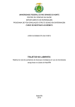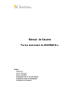
1
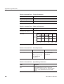
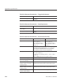
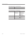
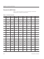
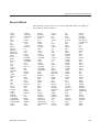
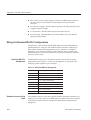
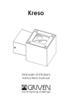
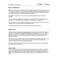
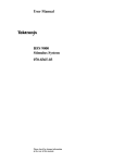
Appendix B: Specifications
The HFS 9000 family of high-speed logic signal source instruments have a
modular architecture with factory-configurable cards. The channels are digitally
synthesized from a common clock resulting in highly accurate independent
placement of rising and falling edges. The instruments are optimized for digital
device characterization with unique triggering capabilities and a variety of pulse
outputs. The product family also features low RMS jitter, the ability to compensate for external cable skews, and an easy-to-use graphical human interface.
This section contains the complete specifications for the HFS 9000 Stimulus
System and Modules. These specifications are classified as either nominal traits,
warranted characteristics, or typical characteristics.
Nominal Traits
Nominal traits are described using simple statements of fact such as “+2.6 V” for
the trait “Maximum high level,” rather than in terms of limits that are performance requirements.
Table B–1: Nominal Traits — HFS 9PG1 Output Performance
Each channel and complement driving a 50 W load to ground, except as noted.
Name
Description
Maximum high level
+2.6 V
Minimum low level
–2.00 V
Maximum amplitude
3.00 V
Minimum amplitude
0.50 V
Level resolution
0.01 V
Operation when terminated
through 50 W to –2 V
Output levels will be approximately 1 V more negative than
the values programmed, specified, and displayed. Actual
output levels more negative than –2 V may cause
malfunction. Level accuracy specifications do not apply
when terminating to –2 V. Both true and complement
outputs must be terminated to the same voltage.
With compliments
Helmut Singer Elektronik
HFS 9000 User Manual
www.helmut-singer.de [email protected]
fon +49 241 155 315
fax +49 241 152 066
Feldchen 16-24 D-52070 Aachen Germany
B–1
Appendix B: Specifications
Table B–1: Nominal Traits — HFS 9PG1 Output Performance (Cont.)
Each channel and complement driving a 50 W load to ground, except as noted.
Name
Description
Operation when terminated to
high impedance loads
Output level range will double until certain internal limits are
achieved. Since the programmed, specified, and displayed
output levels do not match the actual output levels, level
accuracy specifications do not apply when terminating to a
high impedance load. Because of the larger voltage swings
associated with doubled level range, output transition time
specifications do not apply when driving a high impedance
load.
Output limits
One high limit and one low limit may be enabled or disabled
together.
Table B–2: Nominal Traits — HFS 9PG2 Output Performance
Each channel and complement driving a 50 W load to ground, except as noted.
B–2
Name
Description
Maximum high level
+5.50 V
Minimum low level
–2.00 V
Maximum amplitude
5.50 V
Minimum amplitude
0.50 V
Level resolution
0.01 V
Operation when terminated
through 50 W to –2 V
Output levels will be approximately 1 V more negative than
the values programmed, specified, and displayed. Actual
output levels more negative than –2 V may cause
malfunction. Level accuracy specifications do not apply
when terminating to –2 V. Both true and complement
outputs must be terminated to the same voltage.
Transition time 20% to 80%
Variable from 800 ps to 5 ns
Transition time resolution
10 ps
Output limits
One high limit and one low limit may be enabled or disabled
together.
HFS 9000 User Manual
Appendix B: Specifications
Table B–3: Nominal Traits — HFS 9DG1 Output Performance
Each channel and complement driving a 50 W load to ground, except as noted.
Name
Description
Maximum high level
+5.0 V
Minimum low level
–2.5 V
Maximum amplitude
3.00 V
Minimum amplitude
0.01 V
Level resolution
0.01 V
Operation when terminated
through 50 W to –2 V
Output levels will be approximately 1 V more negative than
the values programmed, specified, and displayed. Actual
output levels more negative than –2 V may cause
malfunction. Level accuracy specifications do not apply
when terminating to –2 V. Both true and complement
outputs must be terminated to the same voltage.
Operation when terminated to
high impedance loads
Output level range will double until certain internal limits
are achieved. Since the programmed, specified, and
displayed output levels do not match the actual output
levels, level accuracy specifications do not apply when
terminating to a high impedance load. Because of the
larger voltage swings associated with doubled level range,
output transition time specifications do not apply when
driving a high impedance load.
Output limits
One high limit and one low limit may be enabled or
disabled together.
Table B–4: Nominal Traits — HFS 9DG2 Output Performance
Each channel and complement driving a 50 W load to ground, except as noted.
HFS 9000 User Manual
Name
Description
Maximum high level
+5.50 V
Minimum low level
–2.00 V
Maximum amplitude
5.50 V
Minimum amplitude
0.01 V
Level resolution
0.01 V
Operation when terminated
through 50 W to –2 V
Output levels will be approximately 1 V more negative than
the values programmed, specified, and displayed. Actual
output levels more negative than –2 V may cause
malfunction. Level accuracy specifications do not apply
when terminating to –2 V. Both true and complement
outputs must be terminated to the same voltage.
Transition time 20% to 80%
Variable from 800 ps to 6 ns
B–3
Appendix B: Specifications
Table B–4: Nominal Traits — HFS 9DG2 Output Performance (Cont.)
Each channel and complement driving a 50 W load to ground, except as noted.
Name
Description
Transition time resolution
10 ps
Output limits
One high limit and one low limit may be enabled or disabled
together.
Table B–5: Nominal Traits — Time Base
Name
Description
Frequency range
HFS 9PG1, HFS 9DG1: 50 kHz to 630 MHz
HFS 9PG2, HFS 9DG2: 50 kHz to 300 MHz1
Frequency resolution
≤ 0.1% of frequency setting
Minimum frequency setting when
using half, quarter, or eighth
pulse rate modes2
half pulse rate: 100 kHz
quarter pulse rate: 200 kHz
eighth pulse rate: 400 kHz
Number of pulse periods in burst
or auto-burst modes
User selectable from 1 to 65,536
1
If the HFS 9PG2 or HFS 9DG2 is operated in half pulse rate mode, frequency can be
extended to 600 MHz for the HFS 9PG2 and 630 MHz for the HFS 9DG2.
2
All pulse rate modes result in 50 kHz output frequency.
Table B–6: Nominal Traits — Performance to External Frequency Reference
B–4
Name
Description
PHASE LOCK IN input characteristic
0.1 mF DC blocking capacitor followed by 50 W termination
to ground
Phase lock output frequency
range
Any 2n multiple or sub-multiple of the phase lock frequency
that is within the allowed frequency range for the card being
used
FRAME SYNC IN
Initiates a burst when using phase lock mode
FRAME SYNC IN input characteristic
50 W terminated to –2 V
HFS 9000 User Manual
Appendix B: Specifications
Table B–7: Nominal Traits — Output Edge Placement Performance1
Name
Description
Channel deskew (Chan Delay)
range, channels relative to time
zero reference
–60 ns to 2.0 ms
Channel deskew (Chan Delay)
resolution
HFS 9PG1, HFS 9PG2: 5 ps
HFS 9DG1, HFS 9DG2: 1 ps
Delay (Lead Delay) adjustment
range
Zero to 20 ms
Delay (Lead Delay, Trail Delay)
adjustment resolution
HFS 9PG1, HFS 9PG2: 5 ps
HFS 9DG1, HFS 9DG2: 1 ps
Pulse width adjustment range
HFS 9PG1, HFS 9PG2: Zero to (one period – 790 ps)
inclusive
HFS 9DG1, HFS 9DG2: Zero to (one period × 65,536)
inclusive
Pulse width adjustment resolution
HFS 9PG1, HFS 9PG2: 5 ps
HFS 9DG1, HFS 9DG2: 1 ps
Fine knob resolution of timing
5 ps
1
Measured at 50% levels, each channel independent.
Table B–8: Nominal Traits — Transducer In Performance
Name
Description
TRANSDUCER IN input characteristic
HFS 9PG1: 1000 pF DC blocking capacitor followed by
50 W termination to ground
HFS 9PG2: 100 pF DC blocking capacitor followed by 50 W
termination to ground
Table B–9: Nominal Traits — Skew Cal In Performance
HFS 9000 User Manual
Name
Description
SKEW CAL IN usage
Calibration use only. No signal, except from a channel
OUTPUT connector during the calibration process, should
ever be applied to this input.
B–5
Appendix B: Specifications
Table B–10: Nominal Traits — Trigger In Performance
Name
Description
Input Voltage range
±5 V maximum
Trigger level range
±4.70 V
Trigger level resolution
100 mV
Table B–11: Nominal Traits — Trigger Out Performance
Name
Description
Pretrigger range, TRIGGER OUT
before time zero reference
Zero to 70 ns
TRIGGER OUT pulse width in
auto mode
100
10
Width
(ns)
1
0.1
0.01
0.1
1
10
100
Output Frequency (MHz)
1000
Table B–12: Nominal Traits — Power Requirements
Name
HFS 9003 Description
HFS 9009 Description
Fuse ratings
5 A, 250 V, type 3AG,
(Tektronix part 159-0014-00),
and
4 A, 250 V, type 3AG, fast
blow, (Tektronix part
159-0017-00)
15 A, 250 V, type 3AG, fast
blow, (Tektronix part
159-0256-00)
Table B–13: Nominal Traits — System Memory Performance
B–6
Name
Description
Non-volatile memory retention
time
Instrument settings and calibration constants are retained
in non-volatile memory for 5 years or more. Card
identification is retained for 10 years. Extended storage
above 50_ C may degrade the life of all non-volatile
memory.
HFS 9000 User Manual
Appendix B: Specifications
Table B–14: Nominal Traits — HFS 9003 Mechanical
Name
Description
Weight, in 12-channel configuration. (Shipping weight includes all
standard accessories.)
Net weight:
Shipping weight:
Overall Dimensions
Width:
Height:
Depth:
Depth behind
rack flange:
Cabinet
45 lbs. (20.5 kg)
60 lbs. (27.3 kg)
Rackmount
51 lbs. (23.2 kg)
66 lbs. (30.0 kg)
Cabinet
16.3 in. (414 mm)
7.0 in. (178 mm)
24.75 in. (629 mm)
Rackmount
19.0 in (483 mm)
7.0 in. (178 mm)
24.75 in. (629 mm)
—
22.0 in. (559 mm)
Cooling Method
Forced-air circulation with no air filter, maximum 318 cfm
Construction Material
Chassis parts are constructed of aluminum alloy; bezel is
glass-filled polycarbonate with Lexan plastic inserts; cabinet
is aluminum with textured epoxy paint.
Table B–15: Nominal Traits — HFS 9009 Mechanical
Name
Description
Weight, in 36-channel configuration. (Shipping weight includes all
standard accessories.)
Net weight:
Shipping weight:
Rackmount
81 lbs. (33.7 kg)
100 lbs. (45.3 kg)
Width:
Height:
Depth:
Rackmount
16.75 in (425.79 mm)
14.00 in. (355.89 mm)
24.00 in. (610.11 mm)
Overall Dimensions
HFS 9000 User Manual
Cooling Method, mainframe
Forced-air circulation with air filter, maximum 318 cfm
Cooling Method, power supply
Forced-air circulation, maximum 106 cfm
Construction Material
Chassis parts are constructed of aluminum alloy with Lexan
plastic inserts; cabinet is aluminum with textured epoxy
paint.
B–7
Appendix B: Specifications
Warranted Characteristics
Warranted characteristics are described in terms of quantifiable performance
limits which are warranted. Names of characteristics that appear in boldface type
have checks for verifying the specifications in the Check Procedures section.
Table B–16: Warranted Characteristics — HFS 9PG1 Output Performance
Name
Description
High level accuracy (amplitude
≥ 1 V or high level ≥ 0 V)1
±2% of level, ±50 mV
Low level accuracy (amplitude
≥ 1 V or high level ≥ 0 V)1
±2% of high level, ±2% of amplitude, ±50 mV
Transition time 20% to 80%
(amplitude ≤ 1 V)
≤ 200 ps
1
If amplitude < 1 V and high level < 0 V, accuracy typically meets the specification but
is not guaranteed
Table B–17: Warranted Characteristics — HFS 9PG2 Output Performance
Name
Description
High level accuracy
±2% of level, ±50 mV
Low level accuracy
±2% of high level, ±2% of amplitude, ±50 mV
Transition time accuracy 20%
to 80% (amplitude ≤ 1 V)
±10% of setting, ±300 ps
Table B–18: Warranted Characteristics — HFS 9DG1 Output Performance
Name
Description
High level accuracy (amplitude
≥ 0.5 V)1
±2% of level, ±50 mV
Low level accuracy (amplitude
≥ 0.5 V)1
±2% of high level, ±2% of amplitude, ±50 mV
Transition time 20% to 80%
(amplitude ≤ 1 V)
≤ 250 ps
1
B–8
If amplitude < 0.5 V, accuracy typically meets the specification but is not guaranteed
HFS 9000 User Manual
Appendix B: Specifications
Table B–19: Warranted Characteristics — HFS 9DG2 Output Performance
Name
Description
High level accuracy (amplitude
≥ 0.5 V)1
±2% of level, ±50 mV
Low level accuracy (amplitude
≥ 0.5 V)1
±2% of high level, ±2% of amplitude, ±50 mV
Transition time accuracy 20%
to 80% (amplitude ≤ 1 V)
±10% of setting, ±300 ps
1
If amplitude < 0.5 V, accuracy typically meets the specification but is not guaranteed.
Table B–20: Warranted Characteristics — Time Base
Name
Description
Frequency accuracy
±1%
Table B–21: Warranted Characteristic — Performance to External Frequency
Reference
Name
Description
PHASE LOCK IN frequency
range
6 MHz to 630 MHz
Table B–22: Warranted Characteristics — Output Edge Placement
Performance1
Name
Description
Delay of pulses relative to time
zero reference (Lead Delay)
accuracy
HFS 9PG1, HFS 9PG2: 1% of (Lead Delay + Chan Delay)
±300 ps
HFS 9DG1, HFS 9DG2: 1% of (Lead Delay + Chan Delay)
±50 ps
Pulse width accuracy
HFS 9PG1: 1% of width ±300 ps
HFS 9PG2: 1% of width ±300 ps [for widths w 20 ns]; 1%
of width)300 ps, –500 ps [for widths t 20 ns]
HFS 9DG1: 1% of width )50 –75 ps
HFS 9DG2: 1% of width)50 ps, –250 ps [for widths
w 20 ns]; 1% of width)50 ps, –450 ps [for widths
t 20 ns]
1
HFS 9000 User Manual
Measured at 50% levels, each channel independent.
B–9
Appendix B: Specifications
Table B–23: Warranted Characteristics — Trigger Out Performance
Name
Description
TRIGGER OUT signal levels
Amplitude ≥ 300 mV (–0.5 V ≥ offset ≥ –1.5 V, driving 50 W
to ground)
Table B–24: Warranted Characteristics — Power Requirements
Name
Description
Primary circuit dielectric breakdown voltage
1500 VACRMS, 60 Hz for 10 seconds without breakdown
Primary Grounding
0.1 W maximum from chassis ground and protective earth
ground
Table B–25: Warranted Characteristics — Environmental and Safety
B–10
Name
HFS 9003 Description
HFS 9009 Description
Temperature
Operating: 0_ C to +50_ C
(32_ F to 122_ F)
Non-operating (storage):
–40_ C to +75_ C (–40_ F
to 167_ F)
Operating: 0_ C to +40_ C
(32_ F to 104_ F)
Non-operating (storage):
–40_ C to +75_ C (–40_ F
to 167_ F)
Altitude
Operating: 4 hours at 3,048 m (10,000 feet). Derate
maximum operating temperature by –1_ C (–1.8_ F) for
each 304.8 m (1,000 feet) above 1,524 m (5,000 feet)
Non-operating: 2 hours at 12,192 m (40,000 feet)
Humidity
Operating: t95% RH, non-condensing, from 0_ C to
30_ C (32_ F to 86_ F)
t75% RH, non-condensing, from 31_ C to 40_ C (88_ F
to 104_ F)
(MIL-T-28800E, para 4.5.5.1.2.2, Type III, Class 5)
Shock (non-operating)
MIL-T-28800E, para 4.5.5.4.1, Type III, Class 5
Resistance to mishandling during
bench use (operating)
MIL-T-28800E, para 4.5.5.4.3, Type III, Class 5
Resistance to packaged transportation vibration, sinusoidal, in
shipping package
Drops of 36 inches on all edges, faces, and corners
National Safe Transit Association, test procedure 1A-B-2
Resistance to packaged transportation vibration, sinusoidal, in
shipping package
Packaged sinusoidal vibration
National Safe Transit Association, test procedure 1A-B-1
Resistance to packaged transportation random vibration
MIL-STD-810D, method 514.3, category I, Figure 514.3-1
HFS 9000 User Manual
Appendix B: Specifications
Table B–25: Warranted Characteristics — Environmental and Safety (Cont.)
Name
HFS 9003 Description
HFS 9009 Description
Safety
Listed to UL1244
Certified to CAN/CSA-C22.2 No. 231–M89
IEC Specifications
Installation Category II
Pollution Degree 2
Safety Class I
Typical Characteristics
Typical characteristics are described in terms of typical or average performance.
Typical characteristics are not warranted.
Table B–26: Typical Characteristics — Time Base
Name
Description
RMS jitter
15 ps, ±0.05% of interval
Recovery time between bursts or
auto-bursts
15 ms
Table B–27: Typical Characteristics — HFS 9PG1 Output Performance
HFS 9000 User Manual
Name
Description
Transition time 20% to 80%
Amplitude ≤ 1 V: 150 ps
1 V < Amplitude ≤ 2 V: 190 ps
2 V < Amplitude ≤ 3 V: 225 ps
Output aberrations (beginning
200 ps after 50% point of transition)
Overshoot: +15%, +20 mV
Undershoot: –10%, –20 mV
B–11
Appendix B: Specifications
Table B–28: Typical Characteristics — HFS 9PG2 Output Performance
Name
Description
Operation when terminated to
high impedance loads
Output level range will double until certain internal limits are
achieved. Since the programmed, specified, and displayed
output levels do not match the actual output levels, level
accuracy specifications do not apply when terminating to a
high impedance load. Because of the larger voltage swings
associated with doubled level range, output transition time
specifications do not apply when driving a high impedance
load.
Transition time accuracy 20% to
80%
±10% of setting, ±300 ps
Output aberrations
Overshoot: +15%, +20 mV
Undershoot: –10%, –20 mV
Table B–29: Typical Characteristics — HFS 9DG1 Output Performance
Name
Description
Transition time 20% to 80%
Amplitude ≤ 1 V: ≤ 250 ps, 250 ps
1 V < Amplitude < 2 V: 250 ps
2 V ≤ Amplitude ≤ 3 V: 260 ps
Output aberrations
Overshoot: +15%, +20 mV
Undershoot: –10%, –20 mV
Table B–30: Typical Characteristics — HFS 9DG2 Output Performance
B–12
Name
Description
Operation when terminated to
high impedance loads
Output level range will double until certain internal limits are
achieved. Since the programmed, specified, and displayed
output levels do not match the actual output levels, level
accuracy specifications do not apply when terminating to a
high impedance load. Because of the larger voltage swings
associated with doubled level range, output transition time
specifications do not apply when driving a high impedance
load.
Transition time accuracy 20% to
80%
±10% of setting, ±300 ps
Output aberrations
Overshoot: +15%, +20 mV
Undershoot: –10%, –20 mV
HFS 9000 User Manual
Appendix B: Specifications
Table B–31: Typical Characteristics — Performance to External Frequency
Reference
Name
Description
PHASE LOCK IN amplitude
range
0.8 V to 1.0 V peak-to-peak
PHASE LOCK IN transition time
requirement
20% to 80% in ≤ 10 ns
FRAME SYNC IN signal level
–1.810 V ≤ Vlow ≤ –1.475 V
–1.165 V ≤ Vhigh ≤ –0.810 V
(standard 100 K ECL levels)
Setup time, rising edge of
FRAME SYNC IN signal to rising
edge of PHASE LOCK IN
650 ps minimum
Hold time, high level of FRAME
SYNC IN after rising edge of
PHASE LOCK IN
650 ps minimum
Time from frame sync qualified
phase lock clock cycle to timezero reference
70 ns minimum, 130 ns
Table B–32: Typical Characteristics — Transducer In Performance
Name
Description
TRANSDUCER IN useful frequency range
HFS 9PG1: 25 MHz to > 1 GHz
HFS 9PG2: 5 MHz to 300 MHz
TRANSDUCER IN amplitude
requirement
1.0 V to 1.5 V peak-to-peak
Table B–33: Typical Characteristics — Trigger In Performance
HFS 9000 User Manual
Name
Description
Input resistance
50 W
Trigger level accuracy
±100 mV ±5% of trigger level
Trigger input rise/fall time requirement
≤ 10 ns
Minimum trigger input pulse
width
1 ns
Trigger sensitivity
≤ 500 mV
Time from trigger in to time-zero
reference
70 ns minimum, 130 ns typical
B–13
Appendix B: Specifications
Table B–34: Typical Characteristics — Trigger Out Performance
Name
Description
Pretrigger resolution
250 ps
Table B–35: Typical Characteristics — Power Requirements
B–14
Name
HFS 9003 Description
HFS 9009 Description
Line Voltage
90 VACRMS to 130 VACRMS
or 180 VACRMS to
250 VACRMS, range
switched automatically
90 VACRMS to 104 VACRMS
with maximum 7 cards
installed, 104 VACRMS to
132 VACRMS with maximum
9 cards installed, or
180 VACRMS to
250 VACRMS, range
switched automatically
Line frequency
48 Hz to 63 Hz
Power consumption
540 W maximum
Inrush surge current
50 A maximum up to 40 ms at 110 VAC
100 A maximum up to 40 ms at 220 VAC
1190 W with maximum of 9
cards installed
HFS 9000 User Manual
Appendix C: Interface Specifications
This appendix describes details of the remote interfaces of the Stimulus System,
both the serial port (RS-232-C) and GPIB. Normally, you will not need this
information to use the HFS 9000, but the information is useful when connecting
to controllers of unusual configuration.
This appendix also contains general information that pertains to programming
with both interfaces including a chart of the ASCII character set and a list of
reserved words.
Interface Messages
Table C–1 shows the standard interface messages that are supported by the
HFS 9000.
Table C–1: HFS 9000 Standard Interface
Messages
HFS 9000 User Manual
Message
GPIB
RS-232-C
DCL
GET
Yes
Yes
Yes (provided by Break)
Yes (provided by *TRG)
GTL
Yes
No
LLO
Yes
No
PPC
No
No
PPD
No
No
PPE
No
No
PPU
No
No
SDC
Yes
No
SPD
Yes
No
SPE
Yes
No
UNL
Yes
No
UNT
Yes
No
Listen Addresses
Yes
No
Talk Addresses
Yes
No
C–1
Appendix C: Interface Specifications
Character Set (ASCII Chart)
Table C–2 shows the character set used for all messages to and from the
HFS 9000. This is identical to standard ASCII.
Table C–2: The ASCII Character Set
0
0
1
NUL
DLE
0
1
SOH
DC1
STX
3
ETX
DC3
EOT
5
ENQ
NAK
ACK
7
BS
9
HT
A
LF
B
VT
C
FF
D
CR
E
SO
F
SI
C–2
=
.
M
>
N
62
?
47
O
63
}
n
125
~
110
o
95
124
109
94
_
79
|
m
^
123
108
93
78
{
l
]
122
107
92
77
z
k
\
121
106
91
76
61
46
/
31
L
y
j
[
120
105
90
75
60
45
30
US
15
<
–
RS
K
x
i
Z
119
104
89
74
59
44
29
14
;
,
GS
J
w
h
Y
118
103
88
73
58
43
28
13
:
+
FS
I
v
g
X
117
102
87
72
57
42
27
12
9
*
ESC
H
u
f
W
116
101
86
71
56
41
26
11
8
)
SUB
G
t
e
V
115
100
85
70
55
40
25
10
7
(
EM
F
s
d
U
114
99
84
69
54
39
24
9
6
’
CAN
E
r
c
T
113
98
83
68
53
38
23
8
5
&
ETB
D
q
b
S
112
97
82
67
52
37
22
7
8
%
SYN
BEL
4
a
R
C
p
96
81
66
51
36
21
6
3
$
Q
B
7
‘
80
65
50
35
20
5
6
#
DC4
A
2
6
P
64
49
34
19
4
1
”
5
@
48
33
18
3
4
!
DC2
4
0
32
17
2
3
space
16
1
2
2
126
rubout
111
127
HFS 9000 User Manual
Appendix C: Interface Specifications
Reserved Words
The following is a list of the reserved words of the HFS 9000. You cannot use
these words as names of aliases.
ABUR
ABURS
ABURST
ALI
ALIA
ALIAS
ALL
AMPL
AMPLI
AMPLIT
AMPLITU
AMPLITUD
AMPLITUDE
AUTO
BAUD
BURS
BURST
CAL
CAT
CATA
CATAL
CATALO
CATALOG
CDEL
CDELA
CDELAY
CH1
CH2
CH3
CH4
CID
COAR
COARS
COARSE
COMP
COMPL
COMPLE
COMPLEM
COMPLEME
COMPLEMEN
COMPLEMENT
CONS
CONST
CONSTA
CONSTAN
CONSTANT
COUN
COUNT
COUT
COUTP
COUTPU
COUTPUT
CR
CRLF
DCH
DCHA
DCHAN
DCHANN
DCHANNE
DCHANNEL
DCYC
DCYCL
DCYCLE
DEF
DEFI
DEFIN
DEFINE
DEL
DELA
DELAY
DELE
DELET
DELETE
DESE
DISP
DISPL
DISPLA
DISPLAY
DIT
DITE
DITEM
DMEN
DMENU
DSET
DSETT
HFS 9000 User Manual
DSETTI
DSETTIN
DSETTING
ECHO
EOL
EVEN
EVENT
EVMSG
FACTORY
FINE
FLAG
FLAGG
FLAGGI
FLAGGIN
FLAGGING
FPAN
FREQ
FREQU
FREQUE
FREQUEN
FREQUENC
FREQUENCY
HALF
HARD
HEADER
HIGH
HLIM
HLIMI
HLIMIT
INP
INPU
INPUT
KEY
KRES
KRESO
KRESOL
KRESOLU
KRESOLUT
KRESOLUTI
KRESOLUTIO
KRESOLUTION
LDEL
LDELA
LDELAY
LEV
LEVE
LEVEL
LF
LFCR
LHOL
LHOLD
LIM
LIMI
LIMIT
LLIM
LLIMI
LLIMIT
LOW
LVI
LVIE
LVIEW
MAX
MESS
MESSA
MESSAG
MESSAGE
MIN
MODE
NAME
NEG
NEGA
NEGAT
NEGATI
NEGATIV
NEGATIVE
NONE
NORM
NORMA
NORMAL
ODD
OFF
OFFS
OFFSE
OFFSET
ON
ONE
OUTP
OUTPU
OUTPUT
PAR
PARI
PARIT
PARITY
PER
PERI
PERIO
PERIOD
PGENA
PGENB
PGENC
PGEND
PGENE
PGENF
PGENG
PGENH
PGENI
PGENJ
PGENK
PHAS
PHASE
PLIN
POL
POLA
POLAR
POLARI
POLARIT
POLARITY
POS
POSI
POSIT
POSITI
POSITIV
POSITIVE
PRAT
PRATE
PRET
PRETR
PRETRI
PRETRIG
PRETRIGG
PRETRIGGE
PRETRIGGER
PURGE
PVI
PVIE
PVIEW
RS232
SBIT
SBITS
SLOP
SLOPE
SOFT
TBAS
TDEL
TDELA
TDELAY
THOL
THOLD
TIN
TINP
TINPU
TINPUT
TOUT
TRAN
TRANS
TRANSI
TRANSIT
TRANSITI
TRANSITIO
TRANSITION
TRIG
TRIGG
TRIGGE
TRIGGER
VERBOSE
WIDT
WIDTH
ZERO
C–3
Appendix C: Interface Specifications
Using Debug Mode
You can turn on Debug from either the GPIB or RS-232 menu. The purpose of
debug mode is to let you observe command operation as commands are sent to
the HFS 9000. Debug is especially useful when you are trying to debug a
program and you have the controller set to single-step through the commands.
When debug mode is on, the debug window (see Figure C-1) is displayed above
the menu. This window is present regardless of which menu is displayed.
Figure C-1: The Debug Window
The bottom three rows of the debug window show the most recent commands
received by the HFS 9000, regardless of which interface received them (GPIB or
RS-232). The row of the debug window shows several indicators which appear
only when appropriate. The indicators and their meanings are:
C–4
H
REM. The HFS 9000 is in the remote state. Generally, remote means that the
HFS 9000 expects to receive commands through the GPIB. If local lockout
is enabled with remote, the front panel is rendered inactive (except for the
SRQ button and the pulse generator channel buttons), and the REMOTE
light on the front panel is lit. If local lockout has not been enabled, then
front-panel commands will be entered and executed regardless of the remote
or local state. When you de-assert the remote enable line, local lockout is
reset automatically. Refer to the documentation on your controller to
determine how you control the remote enable line.
H
LLO. The HFS 9000 is in local lockout mode. The front panel is inactive
when both the LLO command is received and REM (remote enable) is
asserted. Use the LLO command to assert local lockout mode. Once local
lockout mode is asserted, you can reset it by de-asserting remote enable.
H
ATN. The attention line is asserted (low) on the GPIB. This means that the
controller is sending an interface command on the bus. When not asserted,
the data I/O lines are carrying data.
H
LADS. The HFS 9000 is addressed on the GPIB to listen.
H
TADS. The HFS 9000 is addressed on the GPIB to talk.
H
RS232 Error. An error has occurred during I/O on the RS-232-C interface.
Check the RS-232-C settings, especially Baud Rate, Parity, and Stop Bits.
This error flag can also occur when the input buffer has overflowed, which
HFS 9000 User Manual
Appendix C: Interface Specifications
may indicate the controller failing to acknowledge that the HFS 9000 has
flagged busy by sending an XOff character. See XOff> below.
You can clear the RS232 Error flag by turning Debug off and then on.
H
>XOff. An XOff character has been received by the HFS 9000 on the
RS-232-C controller. The HFS 9000 has responded by suspending output.
When the HFS 9000 receives an XOn character, output will resume.
H
XOff>. The HFS 9000 has sent an XOff character to the RS-232-C controller
because the HFS 9000 input buffer is nearly full. The controller should
acknowledge the XOff character by not sending any more characters until the
HFS 9000 sends an XOn character. If the controller fails to respond to the
HFS 9000 XOff request within three characters, the RS232 Error flag may
turn on to indicate possible loss of data.
GPIB Function Subsets
The HFS 9000 supports many GPIB function subsets, as listed below. Some of
the listings describe subsets that the HFS 9000 does not support.
HFS 9000 User Manual
H
SH1 (Source Handshake). The HFS 9000 can transmit multi-line messages
across the GPIB.
H
AH1 (Acceptor Handshake). The HFS 9000 can receive multi-line messages
across the GPIB.
H
T6 (Talker). The HFS 9000 becomes a talker when its talk address is sent
with the ATN (Attention) line asserted. It ceases to be a talker when another
device’s talk address is sent with ATN asserted. The HFS 9000 has no
talk-only capability.
H
L4 (Listener). The HFS 9000 becomes a listener when its listen address is
sent with the ATN (Attention) line asserted. The HFS 9000 does not have
listen-only capability.
H
SR1 (Service Request). The HFS 9000 asserts an SRQ (Service Request)
line to notify the controller when it requires service.
H
RL1 (Remote/Local). The HFS 9000 responds to both the GTL (Go To
Local) and LLO (Local Lock Out) interface messages.
H
PPO (Parallel Poll). The HFS 9000 has no parallel poll capability. It does not
respond to the following interface messages: PPC, PPD, PPE, and PPU. The
HFS 9000 does not send out a status message when the ATN (Attention) and
EOI (End of Instruction) lines are asserted simultaneously.
C–5
Appendix C: Interface Specifications
H
DCL (Device Clear). When acting as a listener, the HFS 9000 responds to
the DCL (Device Clear) and SDC (Selected Device Clear) interface
messages.
H
DT1 (Device Trigger). The HFS 9000 responds to the GET (Group Execute
Trigger) interface message.
H
C0 (Controller). The HFS 9000 cannot control other devices.
H
E2 (Electrical). The HFS 9000 uses tri-state buffers to provide optimal
high-speed data transfer.
Wiring for Alternate RS-232-C Configurations
The RS-232-C cable included with the HFS 9000 connects the HFS 9000 to a
standard RS-232-C serial port with a DB-25 female connector configured as
DCE (Data Communications Equipment). If your controller is configured
differently, you will need to obtain or build a different cable or adapter. The
information below will assist a qualified service person to identify or build the
necessary custom cable.
Serial Port DB-9 Pin
Assignments
The HFS 9000 serial port is a 9-pin male connector with the following pin
assignments listed in Table C–3. This port configuration is equivalent to the
Compaq personal computer 9-pin serial port.
Table C–3: Serial Port DB-9 Pin Assignments
Standard Accessory Serial
Cable
C–6
Pin
RS-232-C Signal Name
1
DCD — Carrier Detect
2
RXD — Receive Data
3
TXD — Transmit Data
4
DTR — Data Terminal Ready
5
Signal Ground
6
DSR — Data Set Ready
7
RTS — Request To Send
8
CTS — Clear To Send
9
RNG — Ring Indicator
The standard accessory serial cable supplied with the HFS 9000, Tektronix part
number 012-1241-00, connects the HFS 9000 to a standard RS-232-C serial port
with a DB-25 female connector configured as DCE (Data Communications
Equipment).
HFS 9000 User Manual
Appendix C: Interface Specifications
In effect, the standard accessory serial cable converts the HFS 9000 to a standard
RS-232-C serial port with a DB-25 male connector configured as DTE (Data
Terminal Equipment).
Table C–4 shows the wiring of the standard accessory cable. This table also
shows the standard cable’s effective pin assignments at the DB-25 connector
when the DB-9 connector is attached to the HFS 9000.
Table C–4: Standard Accessory Cable Connections
Connection to IBM PC
DB-25 Ports
DB-9 Female 9-Pin
Connector
Pin Number
DB-25 Male 25-Pin
Connector
Pin Number
RS-232-C Pin Assignments
when Cable Connected to
HFS 9000
1
8
DCD — Carrier Detect
2
3
RXD — Receive Data
3
2
TXD — Transmit Data
4
20
DTR — Data Terminal Ready
5
7
Signal Ground
6
6
DSR — Data Set Ready
7
4
RTS — Request To Send
8
5
CTS — Clear To Send
9
22
RNG — Ring Indicator
The easiest way to connect to an IBM PC or PC clone is to create a “null
modem” or converter. This connects to the IBM PC serial port, and the standard
accessory cable connects to the null modem. The converter is non-polarized; it
can be connected either way between the standard accessory cable and the IBM
PC serial port. The wiring for the null modem is shown in Table C–5.
Table C–5: Converter Wiring for 25-pin PCs
HFS 9000 User Manual
DB-25 Female 25-Pin
Connector Pin Number
DB-25 Female 25-Pin
Connector Pin Number
1
1
2
3
3
2
4
8
5 and 6
20
8
4
20
5 and 6
C–7
Appendix C: Interface Specifications
Connection to IBM PC
DB-9 Ports
To connect the HFS 9000 to an IBM PC or compatible having DB-9 (9-pin)
serial ports, do not use the standard accessory cable at all. Instead, obtain a DB-9
to DB-9 cable with the wiring shown in Table C–6. Either end of this cable may
be connected to either the HFS 9000 or the IBM PC.
Table C–6: Converter Cable for 9-pin PCs1
DB-9 Female 9-Pin
Connector Pin Number
DB-9 Female 9-Pin
Connector Pin Number
1
7
2
3
3
2
4
6 and 8
5
5
6 and 8
4
7
1
1
Neither connector uses pin 9.
With compliments
Helmut Singer Elektronik
www.helmut-singer.de [email protected]
fon +49 241 155 315
fax +49 241 152 066
Feldchen 16-24 D-52070 Aachen Germany
C–8
HFS 9000 User Manual