1
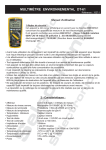
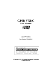
TDS 694C, TDS 684C,
TDS 680C, TDS 654C
Digital Real-Time™ Oscilloscopes
FEATURES AND BENEFITS
3 GHz, 1 GHz and 500 MHz
Bandwidth to Work with the Fastest
Signals in Today’s Digital Designs
10 GS/s and 5 GS/s Sample Rate on
all Channels Simultaneously for Full
Bandwidth Single-shot Capture
Histograms and Measurement
Statistics to More Fully Characterize
Design Performance
Support for Java™ Applications
Packages
Hard Disk Drive Storage (option)
APPLICATIONS
Validation and Characterization of
High Speed Digital Designs
Whether you are working on
next generation microprocessor designs, high-speed data
communications equipment,
or in high-energy physics
research, the TDS 694C captures your fastest signals with
the best fidelity and resolution available. Its 3 GHz
bandwidth preserves your
waveform’s fast rising edges
and accurately shows signal
details. With 10 GS/s digitizing rate simultaneously on all
four channels and a high-stability timebase, the TDS 694C
makes your critical timing
measurements with the highest resolution and accuracy
– even channel-to-channel
measurements made in a single acquisition.
The TDS 600C oscilloscopes
incorporate all the advanced
trigger features you expect in
a high performance oscilloscope. The TDS 694C can be
configured for cross triggering with a Tektronix TLA 700
Logic Analyzer.
The TDS 600C oscilloscopes
give you the total solution to
your digital design characterization and debugging needs.
Now you have the tool you
need to verify design margins, characterize setup and
hold times, and measure
clock-to-data skew on the
fastest digital designs.
The TDS 600C offers 29 automatic measurements, with
measurement statistics, to
make your design verification
and characterization job
much faster and easier.
Available Java-based application packages for Jitter Analysis, Disk Drive measurements
and Processor Specification
measurements provide customized measurements and
analysis capability. The
TDS 600C gives you the performance and features you
need to get your job done
faster and more thoroughly.
Telecommunications/Data
Communications Design
High Energy Physics
With compliments
Helmut Singer Elektronik
Copyright © 1999 Tektronix, Inc. All rights reserved.
www.helmut-singer.de [email protected]
fon +49 241 155 315
fax +49 241 152 066
Feldchen 16-24 D-52070 Aachen Germany
TDS 600 Series
Characteristics
TDS 654C
Total Channels
Sample Rate
(all channels simultaneously)
Real-time Bandwidth
Maximum Record Length
per Channel
Vertical Resolution
TDS 680C
TDS 694C
4
2+2
4
4
5 GS/s
5 GS/s
5 GS/s
10GS/s
500MHz
1 GHz
1 GHz
3GHz
15,000 pts
15,000 pts
15,000 pts
120,000pts
1mV/div – 10V/div
1mV/div – 10 V/div
1mV/div – 10V/div
10mV/div – 1V/div
Time Measurement Accuracy
<50ps @ 5GS/s
<50ps @ 5 GS/s
<50ps @ 5GS/s
15 ps @ 10GS/s
Histograms and Measurement
Statistics
Std.
Std.
Std.
Std.
4 P6243
None
None
None
7 in. color
7 in. mono
7 in. color
7 in. color
Std.
Std.
Std.
Std.
Std. Color
Std. Mono
Std. Color
Std. Color
Opt.
Opt.
Opt.
Opt.
Standard Probes
Display Type
GPIB Port, RS-232 & Centronics
VGA
Hard Disk Drive
TIME BASE SYSTEM
Time Bases – Main and Delayed.
Time/div Range – 200ps/div to 10 s/div.
Except TDS694C: 100ps/div to 10 s/div.
Time Base Accuracy – Over Any Interval
>1 ms ±100ppm. Except TDS 694C: Over
any interval > 1 ms ± 10ppm.
Time Interval Measurement Accuracy –
TDS 654C/680C/684C: ±[(0.2/sample rate)
+ (100ppm x |Reading|)] single shot.
(≈ 50ps @ 5GS/s)
TDS 694C: ±[(0.15/sample rate) + (10ppm
x |Reading|)] single shot. (≈ 15ps @
10GS/s)
Record Length per Channel – 500 to
15,000 pts. Except TDS 694C: 500 to
30,000 pts. (optional: 120,000 pts.)
Trigger Jitter – 8ps RMS (typical).
Pre-Trigger Position – 0% to 100% of
Record.
Channel to Channel Deskew Range –
±25 ns.
VERTICAL SYSTEM
Vertical Resolution – 8-Bits (>11-Bits with
averaging).
Vertical Sensitivity – 1mV/div to 10V/div.
Except TDS 694C: 10mV/div to 1V/div.
Maximum Input Voltage – 300V CAT II;
±400V peak. Derate at 20dB/decade above
1MHz. Except TDS 694C: 5V RMS.
DC Gain Accuracy – ±1.50%. Except
TDS 694C: ±1.0%.
Position Range – ±5 divs.
Offset –
±1V from 1 to 99.5mV/div, ±10V from
100mV to 995mV/div, ±100V from 1V to
10V/div.
Except TDS 694C: ±0.5 V from 10 to
50mV/div, ±0.25V from 50.5 to
100mV/div, ±5V from 101mV to
500mV/div, ±2.5V from 505mV to 1V/div.
Bandwidth Selections – 20MHz, 250MHz,
and Full. Except TDS 694C: Full only.
Input Impedance Selections – 1 MΩ in
parallel with 10pF, or 50 Ω (AC and DC
coupling). Except TDS 694C: 50 Ω
(DC coupled).
Input Coupling – AC, DC or GND. Except
TDS 694C: DC or GND.
page 2
TDS 684C
AC Coupled Low Frequency Limit (Except
TDS 694C) – <10Hz when AC, 1MΩ
coupled. <200kHz when AC, 50 Ω coupled.
ACQUISITION MODES
Peak Detect – High frequency and random
glitch capture. Captures glitches of 1ns
using acquisition hardware at all real-time
sampling rates. TDS 694C captures glitches
of 100 ps.
Sample – Sample data only.
Envelope – Max/min values acquired over
one or more acquisitions.
Average – Waveform data from 2 to 10,000
waveforms (selectable) is averaged.
Single Sequence – Use RUN/STOP button
to capture a single triggered acquisition at a
time, which may be automatically saved to
NVRAM with AutoSave.
TRIGGERING SYSTEM
TRIGGER TYPES
EDGE (Main and Delayed) –
Conventional level-driven trigger. Positive or
negative slope on any channel or rear panel
auxiliary input. Coupling selections: DC, AC,
noise reject, HF reject, LF reject.
LOGIC (Main) –
PATTERN: Specifies a logical combination
(AND, OR, NAND, NOR) of the four input
channels (high, low, don’t care). Trigger
when pattern stays true or false for a specified time.
STATE: Any logical pattern of channels 1, 2,
and 3 (AUX1 on TDS680C) plus a clock
edge on channel 4 (AUX2 on TDS680C).
Triggerable on rising or falling clock edge.
SETUP/HOLD: Trigger on violations of both
setup time and hold time between clock and
data which are on two input channels.
PULSE (Main) –
GLITCH: Trigger on or reject glitches of
positive, negative, or either polarity. Minimum glitch width is 1.0ns with 200ps
resolution.
RUNT: Trigger on a pulse that crosses one
threshold but fails to cross a second threshold before crossing the first again.
WIDTH: Trigger on width of positive or negative pulse either within or out of selectable
time limits (1ns to 1 s).
SLEW RATE: Trigger on pulse edge rates
that are either faster or slower than a set
rate. Edges can be rising, falling, or either.
TDS 600 Series
Characteristics
Continued
TIMEOUT: Trigger on an event which
remains high, low, or either, for a specified
time period, selectable from 1ns to 1 s,
with 200ps resolution.
TLA Cross Trigger (TDS 694C only) – Utilize
a TLA700 logic analyzer to detect a multichannel event, then trigger the TDS 694C.
The trigger points on the TLA and TDS will
be aligned in time.
VIDEO (Optional; Not Available in
TDS 694C) –
Trigger on a particular line of individual,
odd/even, or all fields. Trigger on a specific
pixel of a line by using the video trigger with
delay by events. Choose positive or negative
horizontal sync polarity.
525/NTSC: Choose monochrome or color
(studio-quality NTSC) sync formats.
625/PAL: Choose color or monochrome
(studio-quality PAL) sync formats. HDTV:
Choose from 1125/60, 1050/60, 1250/50,
and 787.5/60 HDTV formats.
Trigger Bandwidth (Edge Type) –
3 GHz (TDS 694C).
1 GHz (TDS 684C, TDS 680C).
500 MHz (TDS 654C).
Main Trigger Modes – Auto, Normal, Single.
Delayed Trigger – Delay by time, events, or
events and time.
Delay by Time Range – 16ns to 250 s.
Delay by Events Range – 2 to 9,999,999
events.
External Trigger Input – Input Impedance:
>1.5 kΩ; Max. InputVoltage: ±20V (DC +
peak AC).
DISPLAY CHARACTERISTICS
Waveform Style – Dots, vectors, variable
persistence from 32 ms to 10 s, infinite persistence, and intensified samples.
Color (TDS 694C, TDS 684C, TDS 654C) –
Standard palettes and user-definable color
for waveforms, text, graticules, and cursors.
Measurement text and cursor colors
matched to waveform. Waveform collision
areas highlighted with different color. Statistical waveform distribution shown with
color grading through variable
persistence.
Color Grading (TDS 694C, TDS 684C,
TDS 654C) – With variable persistence
selected, historical timing information is
represented by temperature or spectral
color scheme (or gray scale on TDS 680C)
providing "z-axis" information about rapidlychanging waveforms.
Graticules – Full, grid, cross-hair, frame,
and NTSC and PAL (with video trigger
option).
Format – YT and XY.
Resolution – 640 horizontal by 480 vertical
displayed pixels (VGA).
Color CRT Monitor (TDS 654C/684C/694C) –
7 in. diagonal NuColor™ liquid crystal full-color
shutter, 256 levels.
Monochrome CRT Monitor (TDS 680C) –
7 in. diagonal, magnetic deflection.
Horizontal raster-scan. P4 white phosphor.
MEASUREMENT SYSTEM
Automatic Waveform Measurements –
Period, frequency, + width, –width, rise
time, fall time, + duty cycle, –duty cycle,
delay, phase, burst width, high, low, max,
min, peak to peak, amplitude, + overshoot,
–overshoot, mean, cycle mean, RMS, cycle
RMS, area, cycle area, extinction ratio
(ratio,dB, %), and mean optical power.
Continuous update of up to four measurements on any combination of waveforms.
Measurement Statistics – Display minimum and maximum or mean and standard
deviation on any displayed single-waveform
measurements.
Cursor Measurements – Absolute,
Delta:Volts, Time, Frequency, and NTSC
IRE and line number (with video trigger
option).
Cursor Types – Horizontal bars (volts), vertical bars (time); operated independently or
in tracking mode.
Histogram Measurements – Mean, median,
standard deviation, hits, waveform count,
peak hits, peak to peak, % mean ± 1, 2, and
3 standard deviations.
WAVEFORM PROCESSING
Waveform Functions – Interpolation (sin(x)/x
or linear), Average, Envelope, Auto Setup.
Advanced Waveform Functions – FFT,
Integration, Differentiation, Waveform (math
or acquired) Limit Testing.
Arithmetic Operators – Add, Subtract,
Multiply, Divide, Invert.
Waveform Limit Testing – Compares
incoming or math waveform to a reference
waveform’s upper and lower limits.
Waveform Histograms – Both vertical and
horizontal histograms, with periodically
updated measurements, allow statistical
distributions to be analyzed over any region
of the signal.
Dual Window Zoom – Dual graticules
simultaneously show selected and zoomed
waveforms. Up to two zoom boxes show
areas on the selected trace that are being
magnified, and the two magnified areas can
be overlapped for quick comparison. Color
of zoomed trace matches selected trace.
POWER REQUIREMENTS
Line Voltage Range – 90 to 250V RMS.
Line Frequency – 45 to 440Hz.
Power Consumption –
300 W max. (TDS 654C/680C/684C)
450 W max. (TDS 694C)
ENVIRONMENTAL AND SAFETY
Temperature –
Operating: +4°C to +45°C (floppy not used),
+10°C to +45°C (floppy in use). Non-operating:–22°C to +60°C.
TDS 694C: Operating: +5°C to +40°C
(floppy not used), +10°C to +40°C (floppy in
use). Non-operating:–22°C to +60°C.
Humidity –
Operating: 20% to 80% RH at or below
+32°C.
With compliments
Helmut Singer Elektronik
www.helmut-singer.de [email protected]
fon +49 241 155 315
fax +49 241 152 066
Feldchen 16-24 D-52070 Aachen Germany
page 3
TDS 600 Series
Characteristics
Continued
Altitude –
Operating: 15,000 ft. (hard disk not used),
10,000 ft. (hard disk in use). Non-operating:
40,000 ft.
Electromagnetic Compatibility – Meets or
exceeds EN55011 Class A Radiated and
Conducted Emissions; EN 50081-1;
EN60555-2 Power Harmonics; FCC 47 CFR,
Part 15. Subpart B, Class A; Australian EMC
Framework; EN 50082-1
Safety – UL 3111-1, CSA-22.2 No. 1010.1
TDS 600 Series TDS 694C
Ordering
Information
PHYSICAL CHARACTERISTICS
Dimensions
mm
in.
Height with feet
Height without feet
Width with handle
Depth with front
cover installed
193
178
445
434
7.6
7
17.5
17.1
kg
lbs.
14.1
24.0
31
53
Weight
Net approximately
Shipping Weight
approximately
Options Available
Four-channel Color 3GHz, 10GS/s Per
Channel, Digital Real-Time Oscilloscope.
Includes: User Manual (070-0473-00),
Quick Reference Guide (071-2313-00), Programmer’s Manual in MS-Help format on
floppy disk (063-3060-00), Technical Reference (Performance Verification) Manual
(071-0496-00), Probe Deskew Fixture
(679-4809-00), Footswitch and Adapter
(260-1189-02 and 013-0312-00).
Opt. 05 – Video Trigger, NTSC, PAL, HDTV,
FlexFormat™. (Except TDS 694C)
Opt. 1K – Model K420 Instrument Cart.
Opt. 1M – 120 k Record Length.
(TDS 694C only)
Opt. 1R – Rackmount Kit.
Opt. 31 – Add 1 ea. P6339A Buffered
Passive Probe. (TDS 694C only)
Opt. 33 – Add 1 ea. P6158 Low Capacitance
Probe. (Except TDS 654C)
Opt. 34 – Add 1 ea. P6247 Differential
Probe. (Except TDS 694C)
Opt. 35 – Add 1 ea. P6243 Active Probe.
(TDS 654C Only)
Opt. 36 – Add 1 ea. P6139A Passive Probe.
(Except TDS 694C)
Opt. 37 – Add 1 ea. P6245 Active Probe.
(Except TDS 654C)
Opt. 38 – Add 1 ea. P6249 4 GHz Active
Probe. (TDS 694C only)
Opt. 39 – Add 1 ea. P6248 1.7 GHz
Differential Probe. (TDS 694C only)
Opt. HD – Internal Hard Disk Drive.
TDS 684C
Four-channel Color 1 GHz, 5 GS/s Per
Channel Digital Real-Time Oscilloscope.
TDS 680C
Two-channel Monochrome 1 GHz, 5 GS/s
Per Channel Digital Real-Time Oscilloscope.
TDS 654C
Four-channel Color 500MHz, 5 GS/s Per
Channel Digital Real-Time Oscilloscope.
Includes: Four P6243 FET Probes.
TDS 684C/680C/654C Include
User Manual (070-0130-00), User Supplement (071-0273-00), Quick Reference
Guide (020-2235-00), Programmer's Manual in MS-Help format on floppy disk (0633120-00), Technical Reference Manual
(071-0272-00).
International Power Plug Options
Opt. A1
Opt. A2
Opt. A3
Opt. A5
All Include
Front Cover (200-3696-00),
North American Power Cord (161-0230-01),
Accessory Pouch 016-1268-00 (Except
TDS 680C).
– Universal Euro 220V, 50Hz.
– UK 240V, 50Hz.
– Australian 240V, 50Hz.
– Switzerland 220V, 50 Hz.
Software
With compliments
Helmut Singer Elektronik
TDS JAVA™ APPLICATIONS
TDSJIT1 – Jitter and timing analysis
application.
TDSDDM1 – Hard disk drive measurement
application.
TDSPSM1 – Processor specifications
measurement application.
www.helmut-singer.de [email protected]
fon +49 241 155 315
fax +49 241 152 066
Feldchen 16-24 D-52070 Aachen Germany
For further information, contact Tektronix:
Worldwide Web: for the most up-to-date product information visit our web site at: www.tektronix.com
ASEAN Countries (65) 356-3900; Australia & New Zealand 61 (2) 9888-0100; Austria, Central Eastern Europe, Greece, Turkey, Malta,& Cyprus +43 2236 8092 0; Belgium +32 (2) 715 89 70;
Brazil and South America 55 (11) 3741-8360; Canada 1 (800) 661-5625; Denmark +45 (44) 850 700; Finland +358 (9) 4783 400; France & North Africa +33 1 69 86 81 81; Germany + 49 (221) 94 77 400;
Hong Kong (852) 2585-6688; India (91) 80-2275577; Italy +39 (2) 25086 501; Japan (Sony/Tektronix Corporation) 81 (3) 3448-3111; Mexico, Central America, & Caribbean 52 (5) 666-6333;
The Netherlands +31 23 56 95555; Norway +47 22 07 07 00; People’s Republic of China 86 (10) 6235 1230; Republic of Korea 82 (2) 528-5299; South Africa (27 11)651-5222; Spain & Portugal +34 91 372 6000;
Sweden +46 8 477 65 00; Switzerland +41 (41) 729 36 40; Taiwan 886 (2) 2722-9622; United Kingdom & Eire +44 (0)1628 403300; USA 1 (800) 426-2200.
From other areas, contact: Tektronix, Inc. Export Sales, P.O. Box 500, M/S 50-255, Beaverton, Oregon 97077-0001, USA 1 (503) 627-6877.
Copyright © 1999, Tektronix, Inc. All rights reserved. Tektronix products are covered by U.S. and foreign patents, issued and pending. Information in this
publication supersedes that in all previously published material. Specification and price change privileges reserved. TEKTRONIX and TEK are registered
trademarks of Tektronix, Inc. All other trade names referenced are the service marks, trademarks or registered trademarks of their respective companies.
5/99
HB/XBS
55W-10066-7