1
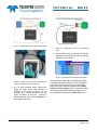
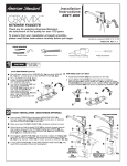
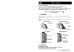
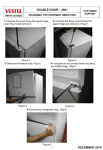
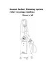
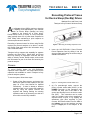
TECHNICAL
BRIEF
Recording Protocol Traces
for Device Sleep (DevSlp) Drives
Matthew Dunn and Peter Lizak
Teledyne LeCroy Protocol Solutions Group
A
s solid-state drives (SSDs) continue to develop
in capability and sophistication, new features
such as Device Sleep (DevSlp) are being
added to the feature set of many drives.
DevSlp allows a drive to “sleep” in a very low power
state (typically about 5% of power draw compared to
IDLE mode) while maintaining a quick response to
access requirements for the drive.
Recording of protocol traces for drives using DevSlp
requires the protocol analyzer to be able to monitor
the DevSlp state and record this information along
with normal data traffic.
Teledyne LeCroy supports this capability for systems
including the Sierra M6-2, Sierra M6-4 and Sierra
M124 by offering an expansion card that has the
ability to directly monitor DevSlp status, and records
this information as part of the trace file stored by the
protocol analyzer.
Figure 1: Removing an existing expansion card
2. Insert the ACC-EXP-005-X Sierra External
Power Expansion Card by sliding it into the
slots provided and tighting the screws using a
standard screwdriver.
Process
To record DevSlp status, the ACC-EXP-005-X
expansion card is required. This card inserts into the
expansion slot available on certain Teledyne LeCroy
protocol analyzer systems.
To use the system, follow these steps:
1. Power off the Sierra system, and remove the
blank cover plate from the expansion slot (see
page 32 of the User Manual for detailed
instructions). If there is already a different
expansion card in use, remove the expansion
card by using the special removal tool
supplied and slowing backing the existing
expansion card out by loosening one side at a
time until the card is fully released.
Recording Protocol Traces for Device Sleep (DevSlp) Drives
Figure 2: Inserting the ACC-EXP-005-X card
3. (a) For pass-through mode, connect the
power or power sense cable (921671) to the
POWER connector on the expansion card.
Connect the other end of the cable to the
ground and DevSlp line on the device under
test (DUT). This connection can be made
either by soldering short wires (supplied) to
exposed traces or pins, or by clipping the
attachment clips (also supplied) to pins.
Connect SATA data cables from the HBA to
the Initiator port on the analyzer and then
from the Target port of the analyzer to the
DUT.
Teledyne LeCroy
Page 1 of 2
TECHNICAL
BRIEF
Figure 3: Configuration used for pass-through mode
Figure 5: Configuration used for Host Emulation
mode
4. Record traces in the normal way. The DevSlp
status will be recorded in the trace and will be
displayed by the software.
Figure 6: Recorded trace showing DevSlp status
Figure 4: Attachment of probe leads to DevSlp and
GND pins (attachment clips shown here)
3. (b) For host emulation mode, connect the
power or power sense cable (921095 or
921097) to the power connector on the
exansion card. Connect the other end to the
power connector on the DUT. Connect a
SATA cable from the from the Target port of
the analyzer to the DUT.
To show Device Sleep status in Packet View during
Command sequences, open up any FIS Type packet
to the Link level then right-click on the green Link
field. On the menu that then appears choose Show
Field then Device Sleep as shown. Likewise, to show
Device Sleep during OOB sequences right-click on
any OOB packet to bring up the Show Field menu.
Recording Protocol Traces for Device Sleep (DevSlp) Drives
Teledyne LeCroy
Page 2 of 2