1
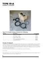
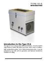
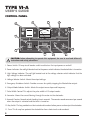
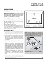
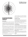
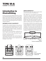
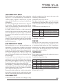
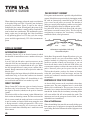
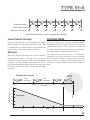
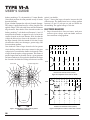
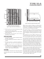
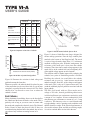
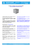
Since 1964, the leader in effective, safe and reliable products for fisheries conservation. Knowledgeable biologists depend upon Smith-Root equipment. USER’S MANUAL TYPE VI-A ELECTROFISHER SMITH-ROOT, INC. Products for Fisheries Conservation WWW.SMITH-ROOT.COM #07299.09 Contents Introduction to the Type VI-A ....................... 1 Type VI-A Combo.......................................... 1 Control panel................................................. 2 Connections.................................................. 3 Operating Procedures.................................... 3 Set-Up Procedure.......................................... 3 Electrofishing Procedure................................ 4 Generator Speed............................................ 4 Trouble Shooting........................................... 4 Overload Protection...................................... 4 Thermal Protection........................................ 4 General Maintenance.................................... 4 Specifications................................................. 5 Electrofishing Safety...................................... 7 Preventing Electrical Shock............................ 8 Planning For Safety........................................ 8 Backpack Safety............................................. 9 Boat Safety.................................................... 9 Do's & Don'ts ............................................... 9 Introduction to Electrofishing....................... 10 Types of Current.......................................... 11 Electrode Design.......................................... 13 Field Techniques.......................................... 17 Electrofishing Reference & Training Materials........................................ 18 Items manufactured by companies other than Smith-Root carry the original manufacturer’s warranty. Please contact product manufacturer for return instructions. All Smith-Root, Inc. manufactured products are covered by a one-year warranty. Credit & Refund Policy: Customers returning equipment - in new condition - will be given a refund within five days from the date of the return. A return authorization must accompany returns. Valid equipment returns include, but are not limited to, ordering incorrect equipment, funding deficits and defective equipment returned for reimbursement. All returns are subject to a restocking fee and applicable shipping charges. The restocking fee is figured at 10% of the purchase price but not less than $20.00. Customers receiving equipment in damaged condition will be referred to the shipping company for insurance reimbursement. Rev.09 © 2007 Smith-Root, Inc. Vancouver, WA - USA www.smith-root.com I TYPE VI-A USER’S GUIDE Type VI-A Combo Package Includes the Following: Quantity Description Line Number 1......................................Type VI-A Electrofisher......................................................... 00859 1......................................Input Power Cable................................................................ 03426 1......................................Output Power Cable............................................................ 03425 1......................................15 ft. Single Foot/Hand Switch............................................. 03302 1......................................Instruction Manual............................................................... 07299 Receipt of shipment Carefully remove electrofisher from its shipping container and examine closely for shipping damage. If parts are missing or the unit is damaged, notify the transportation company and immediately file a claim for the amount of damage. This operator’s manual contains important information about the operation and maintenance of your unit. We suggest you keep this manual and refer to it when making adjustments or ordering parts. Additional copies are available for a nominal charge from Smith-Root Inc. Record the serial number of your type VI-A electrofisher in the space provided below: Serial number__________________________________ When ordering parts, always quote the electrofisher model and serial number located on the unit’s nameplate. This is essential to ensure that the correct part is shipped to you. II ELECTROFISHERS TYPE VI-A INTRODUCTION Introduction to the Type VI-A The type V1-A is a heavy-duty 5kW electrofisher. It can be used in large bodies of water like lakes and rivers, and in low to mediumhigh conductivity waters: 10 to 1000 microsiemens/cm3. It can be powered by any 240 volt AC generator and features transformer isolation for safety. 1 www.smith-root.com TYPE VI-A USER’S GUIDE CONTROL PANEL 3 8 9 4 354 7 DANGER HIGH VOLTAGE READY INPUT POWER F OF F OF VDC VAC 10 AMP READ INSTRUCTIONS 60 HZ AC OFF 2 FUSE VOLTAGE SELECTOR EMERGENCY SHUTDOWN POWER 4 5 IND. SECONDS SMITH-ROOT, INC. 11 88 62 VDC AC AMPERES OFF 1 707 500 0 VAC 10 HV 375 75 0 0 0 0 2 8 530 61 0 4 250 5 12 10 TIMER 17 6 VANCOUVER, WA USA 60 PPS DC 120 PPS DC TYPE VI-A ELECTROFISHER SERIAL NO. OOOOO 10 1 ms OUTPUT MODE 7 ms 7 PULSE WIDTH 5 6 CAUTION: before attempting to operate this equipment, be sure to read and follow all instructions and safety precautions. 1. Power Switch: 25 amp circuit breaker switch used to turn the input power on and off. 2. Power Indicator: the red light located next to the power switch indicates the electrofisher is turned on. 3. High Voltage Indicator: The red light located next to the voltage selector switch indicates that the high voltage has been activated. 4. Voltage Selector Switch: Selects the output voltage. 5. Emergency Shutdown Switch: Provides a means for quickly stopping the Electrofisher output. 6. Output Mode Selector Switch: Selects the output wave shape and frequency. 7. Pulse Width Control: This adjusts the pulse width in DC output modes. 8. Ammeter: Shows the current flowing through the water via the electrodes. 9. Seconds Counter: Records actual shocking time in seconds. The counter records one count per second when the output is activated and the timer is turned on. 10. Key Switch: The key provided must be inserted and turned on before power can be output the electrodes. 11. Fuse: This 8 amp fuse protects the electrofisher from short circuits and overloads. 2 ELECTROFISHERS VVP-15B TYPE VI-A 4-pin Anode 4-pin CONNECTIONS & Cathode SET-UP & Control Plug & Control Plug AC Output CONNECTIONS& Control Input DC Output & Control Input Plug: The power cord from the generator plugs into this 3-pin connector. Remote Foot Switch Plug: Foot switches provided are plugged into this 4-pin connector. The Key switch and the Emergency Shutdown switch must also be activated to get the output to the electrodes. Output plug: The anode 2.5 GPP andand 5.0cathode GPP output cables are connected to this 2-pin connector. Pin A goes to the anode and Pin B goes to the cathode. Type VI-A The cable connectors on the type VI-A are easily distinguished by the number of pins. Operating Procedures Control is a short Output power powerto set The following summary of theInput procedures 4-pin female 7 VI-A pin female 7 pin up and operate the Type Electrofisher. Be male sure to also read the Safety Precautions and the Electrofishing Principles sections before starting the generator. Input power 3-pin female Control 4-pin female Output power 2 pin female Above: Type VI-A Connectors Set-Up Procedure 1. Connect suitable electrodes to the output cable provided. The black wire connects to the cathode and the red wire to the anode. Plug the 2-pin connector into the electrofisher. 2. Connect the input power cable between the generator and the electrofisher. Caution: Do not plug an electrofisher that is wired for 240 volts into a 120 volt generator, or GPP put an electrofisher7.5 that is wired for 120 volt into a 240 7.5 GPP volt generator. NOTE: For greater safety and more flexibility, it is recommended that a RCB-6B Junction Box be used in the connecting of electrode devices. A RCB-6B can be used in both shore and boat operations. Power Source 9.0 GPP 7.5 GPP 3. If grounding is called for in local codes, or radio interference necessitates it, do the following: On the shore drive a 3/4 or 1 inch pipe into the ground as close to the unit as possible. This pipe must penetrate moist earth. To this pipe connect a ground clamp, and run a No. 10 wire from it to the battery negative terminal Control Output power on the control panel or topower the generatorInput ground stud. Do 4-pin female 7-pin female 7-pin not connect to a water pipe or a ground used male by a radio system. When used in a metal-hulled boat, ensure that the generator frame is grounded to boat hull. This will prevent a shock should you experience an electrical failure. 4. Connect the remote foot switch to the electrofisher. The on/off switch is to be used by the electrofisher operator and the foot switch by the netter. Anode RCB-6B Type VI-A Control Output powerCathode Input power 4-pinhookup femaleof RCB-6B, 1-pin female 7-pin male Typical Electrodes and Electrofisher. RCB-6B for Type VI-A.......................#08747 3 www.smith-root.com TYPE VI-A USER’S GUIDE ELECTROFISHING PROCEDURE 1. Start the engine on the generator. 2. Adjust the Mode Selector Switch to the desired mode. It is recommended that you use one of the pulsed DC positions. 3. Make sure all personnel are clear of the electrodes. 4. Turn on the power switch. The power indicator lamp should come on. 5. Adjust the Pulse Width Control to approximately 3.5ms. 6. Set the Voltage Selector Switch to the lowest setting. 7. Insert the key provided into the Key Switch on the front panel. Turn it to the ON position. 8. Lift the cover on the Emergency Shutdown switch and move it to the ON position. 9. Both operators should now activate their control switches. The High Voltage indicator lamp should come on. You should also see a deflection of the ammeter. 10. Adjust the Pulse Width Control and Voltage Selector Switch as necessary. Caution: Do not adjust the Voltage Selector switch or the Mode Selector switch under load. Always turn off the Key Switch or the Emergency Shutdown Switch first. Damage to the switches may result from switching under load. 11. Experiment to learn what mode settings and voltage settings are best for water conditions and the fish being shocked. Read section C for useful data. GENERATOR SPEED The generator must be run at proper speed to furnish the electrical power it was built to produce. All engines have a tendency to slow down when a load is applied. The speed governor tries to hold the speed as near constant as possible, but when the electrical load is increased, the engine speed will always drop slightly. This, together with the voltage drop within the generator, results in lower voltage loaded than when running unloaded. The decrease in engine speed will also affect the output frequency slightly. 4 ELECTROFISHERS TROUBLE SHOOTING The Type VI-A has a long history of reliability in the field, but problems can occur. The electrofisher has built-in protection devices to prevent it from being damaged by overloading and overheating. OVERLOAD PROTECTION An overload occurs any time the load on the output is greater than the electrofisher can deliver. Common causes of overloads are shorting the output anode to the cathode by touching them together, working in water too conductive for the unit, working with too high a voltage for the water’s conductivity, and short circuits within the unit or the cables. The Type VI-A is protected from overloads and short circuits by an 8 amp fuse on the output circuit, and a 25 amp circuit breaker on the input circuit. If the 8 amp fuse blows or the 25 amp circuit breaker kicks off, reduce either the Pulse Width or the Voltage Selector to a lower setting. Make sure that the anode is not shorted to the cathode. THERMAL PROTECTION The greatest limiting factor in a transformer is its ability to dissipate heat. Because of weight limitations, the transformer in the Type VI-A is air-cooled. An internal fan is used to cool the transformer, but, under very heavy load, the transformer will eventually get too hot. To prevent damage from occurring to the transformer, a thermal cut-off switch has been installed in the transformer. The thermal switch turns off the output while the transformer gets too hot, and it won’t turn on again until the transformer has been cooled. GENERAL MAINTENANCE Store the Electrofisher in a dry room free from extremes of temperature. Clean the front panel of the unit with a mild spray-on cleaner. Protect the unit from continuous vibration and severe impacts. Transport it well secured and protected from bouncing into other objects while being transported over rough roads. Regularly check the connectors and wires for damage or corrosion. TYPE VI-A SPECIFICATIONS SPECIFICATIONS Conductivity Range.........................................................................10-1,000 micromhos Input Voltage.............................................................................120 or 240 volt AC 60 Hz Voltage Indicators................................................................................. Front panel neon Output Voltage, AC..............................................................0-707 V RMS in 117 V steps Output Voltage, DC...........................................................0-1,000 V peak in 167 V steps Output Wave shape, AC.................................................................................. Sine Wave Output Wave shape, DC................................................................Fast rise, slow decay Output Frequency, AC............................................................................................. 60 Hz Pulse Frequency, DC.................................................................. 60 or 120 pps selection Input and Output connectors..............................................................MS environmental Input and Output cables..................................... 15’ heavy packed neoprene-jacketed Output Power AC.............................................................5,000 watt maximum at 707 V Output Power DC...........................................................5,000 watt maximum at 1,000V Output Current......................................................................................10 amp AC or DC Output Metering.........................................................................0-10 amp current meter Safety Devices........................................................................ Hand switch & foot switch must be operated simultaneously Isolation.........................................................................Transformer completely isolates electrofisher output from generator and/or boat. Input Circuit Protection...............................25 amp magnetic-hydraulic circuit breaker Output Circuit Protection.................................................... 10 amp fuse, 3AG fast blow Isolation Transformer.............................................................................. Thermal switch Timer Display.................................................................................... Mechanical register Timer Rate........................................................................................ 1 count per second Timer Accuracy.................................................................................................. 5 percent Cabinet Construction....................................................................Heavy-duty aluminum, welded seams, see-through top, carry handles Dimensions................................................................................. 20”L x 10.5”W x 15.5”H Instrument Weight..................................................................................................75 lbs. 5 www.smith-root.com TYPE VI-A ELECTROFISHING SAFETY At least two members of the crew should be qualified to administer cardiopulmonary resuscitation. As opportunities arise, all crew members should attend a course in basic life-support training. ELECTROFISHING SAFETY SAFE FISHING ELECTRICAL SHOCK Electrofishing equipment uses voltages and currents that can be lethal to humans. The operators must always keep in mind that the chance of receiving an electrical shock is multiplied in or near water. Using an electrofisher is like using a firearm: if used properly and with good judgment it is perfectly safe; lose respect for it and you can lose your life! Electrical equipment used in a moist field environment is always subject to deterioration that could lead to dangerous electrical shock. Field equipment is also subjected to vibration and impact during transporting and while in operation. Often equipment shared by different crews does not receive proper maintenance or a complete checkout. Follow the safety guidelines, and use good common sense to handle unforeseen circumstances. All personnel involved in electrofishing should be taught the fundamentals of electricity, and have an understanding of the safety requirements. The most important factor in electrofishing efficiency and safety is the training and experience of the crew. It is the current that passes through the human body that does the damage. The voltage is relevant, because it is the force that “pushes” the current through the body. Experiments show that 20 to 500 Hz AC current is more dangerous than DC, or higher frequencies of AC. The voltages used by electrofishing gear cause death by one of three means: Ventricular Fibrillation Ventricular fibrillation is uncoordinated contraction of the muscles of the heart. The heart quivers rather than beats. Electrical current through the chest can cause this condition. Once a person goes into ventricular fibrillation, the only way to stop the quivering is to use a defibrillator that applies a pulse shock to the chest to restore heart rhythm. Cardiopulmonary resuscitation may help to keep a victim alive until he can be defibrillated. Respiratory Arrest The respiratory center is at the base of the skull. Thus, shocks to the head can cause the breathing to stop. Artificial respiration by the mouth-to-mouth method should be used in this case. Asphyxia Asphyxia is caused by contraction of the chest muscles. 7 www.smith-root.com TYPE VI-A USER’S GUIDE When a current is above a certain level, a person cannot let go of an electrically hot wire. Currents above this level may not cause ventricular fibrillation, but may be enough to cause contraction of the chest muscles. If the current is not stopped, or the victim is not removed from the point of electrical contact, asphyxia will result. Artificial respiration or cardiopulmonary resuscitation may be necessary. To prevent electrical shock all electrical equipment should be carefully inspected before each field operation. With all electrical equipment in good operating condition, and all insulation, junction boxes, bonding, and connections intact, there is much less danger of receiving an electrical shock. Preventing Electrical Shock Electricity needs to have a complete electrical circuit in order for current to flow. The only way that you can get shocked is if you become the electrical conductor to complete the circuit. The current flows from the cathode to the anode through the water. The water is the electrical conductor. If you touched both the anode and the cathode you would become an electrical conductor and complete the circuit path and get a severe electrical shock. If you were to touch only one of the electrodes, you would not complete the electrical circuit and not get shocked. WARNING: Touching any electrode is not recommended. Unless all conductive objects you come into contact with are connected to the same electrode, you will be shocked to find a current path that is not obvious, e.g., the water, or the boat. Preventing electrical shock means preventing electrical current from entering and flowing through parts of the body. The skin is a partial but variable barrier, because it offers resistance to the passage of electrical current. Tough skin has more resistance than tender skin, and dry skin more then wet skin. But tough dry skin alone does not offer enough protection for electrofishing. Rubber lineman’s gloves, rated 5,000V minimum should always be worn. Even while wearing rubber gloves and waders, never touch an electrode while the circuit is energized. Do not work on the electrical system while the generator is running. Do not enter the water while the current is on during boom shocking operations. 8 ELECTROFISHERS A severe electrical shock from electrofishing gear may result in the need for artificial respiration; therefore it is imperative that no one ever works alone. Planning For Safety 1. Never electrofish alone! A minimum of two properly trained people are required for every electrofishing crew. 2. A crew leader shall be appointed for all electrofishing. The crew leader is responsible for the safety of the crew, and the enforcement of all safety regulations. 3. The crew leader, and at least one additional crew member, shall receive training in cardiopulmonary resuscitation (CPR), and First Aid. 4. All electrofishing personnel shall receive training in fundamentals of electricity and safety. 5. Check your electrofisher before each operation, to ensure that it is in good working order. 6. Turn off your electrofisher before making any connections or part replacements. 7. When not in use, and when transporting the unit, disconnect the power supply. 8. Check that the electrofisher gives an audible signal when there is voltage present at the anode. 9. Do not make any field modifications to your electrofisher without written approval from the manufacturer or a qualified electrical engineer. 10. Use only dip nets with insulated handles. 11. Wear personnel flotation devices. 12. Wear lineman’s gloves, rated 5,000V minimum. 13. Never reach into the water in vicinity of an electrode, even if rubber gloves are being worn. 14. Take frequent breaks. Stress and fatigue endanger the crew. 15. Practice the quick release system as shown on page C-6. TYPE VI-A ELECTROFISHING SAFETY BACKPACK SAFETY 1. Before each operation, check that the frame emergency release is in working order and check that the tilt switch shuts off power if the unit is tipped more than 45° 2.Wear hip boots or chest-high waders, with non-skid soles. 3. Wear polarized sunglasses to help you detect sub-surface hazards and obstacles. Beware of turbid water that can hide unseen sub-surface obstacles and sudden drop-offs. 4.Shut off your electrofisher before entering or leaving a stream. 5. Do not operate an anode pole when carrying a backpack unit weighing more than 20 pounds when in hazardous conditions. 6. If you get water in boots, waders, or gloves, stop work immediately and get dry clothing 7.Operate slowly and carefully. Footing in most streams is poor, and most falls often occur when operators are hurrying. BOAT SAFETY DO'S & DON'TS Do’s: 1. A lways be sure that all personnel are clear of the electrodes before turning on the power. 2. Know how to administer first aid treatment for electrical shock. 3. Wear flotation devices. 4. H ave electrical circuits checked only by qualified technicians. 5. Disconnect the power supply when the electrofisher is not in use. Don’ts: 1. Don’t electrofish alone! 2. Don’t continue to electrofish if your boots or gloves get wet inside. 3. Don’t operate an electrofisher if you have had any prior heart ailments. 4. Don’t operate generators without covers or screens. 5. Don’t operate generators without a spark arrester. 1.Ground the generator to the boat hull. 2. Be sure that all the metal parts on the boat are bonded to each other electrically. 3.Run all cables through electrical conduit, or use a heavy-duty rubber-covered cord recommended for wet locations. 4.Make all electrical connections in water-tight junction boxes. 5.Each dip netter should have his own foot switch to control the output. The switch should be wired in series with the emergency off switch of the boat operator. 6.When wading with a boat, even in shallow water, chest waders should be worn. An operator may trip, end up in a kneeling or sitting position in the water and receive a shock. 7. All crew members must be alert Operators who control the power switch must be constantly aware of the netters in the electrical field. 9 www.smith-root.com TYPE VI-A USER’S GUIDE Introduction to Electrofishing WATER CONDUCTIVITY The conductivity of the water and that of the fish’s flesh are the factors that affect electrofishing most. The conductivity of water depends on the quantity of dissolved salts and minerals in the water. The conductivity of potable waters in the United States ranges from 20 to 2,000 microSiemens per centimenter. Sufficient current at realistic power levels will flow through water in this range to electrofish successfully. Figure 2 illustrates the field patterns caused by the presence of a fish in water. In (a) no distortion is caused by the presence of the fish. In low conductivity water, (b), the distortion of the electric field is such that the voltage near the fish is less than it was before the fish was present. The reverse is true in (c) where the water conductivity is more than that of the fish. In this case the distortion is caused by the current concentrating in the water surrounding the fish. In both (b) and (c) not as much power is transferred into the fish’s body as in (a). For many years it has been known that fish react to electric current passed through water. Electricity was first used for fishing in 1863 when a British patent was granted. Major efforts to apply electricity as a tool in fisheries management did not occur until after 1950. Since then detailed studies have been made on the physiological effects of electricity on aquatic organisms. RESPONSE OF FISH TO ELECTRICITY To collect fish by electrical means we must create an electrified zone of sufficient amplitude to stun fish. In the basic electrofishing circuit, shown in Figure 1, a current is passed between submerged electrodes. A fish between these electrodes forms part of a closed circuit and some current flows through its body. The effectiveness of the electrofisher is affected by nine factors: voltage, electrode shape, water conductivity, water temperature, conductivity of the stream bed, fish’s distance, size, species, and time in the field. If these environmental factors are too far out of line, poor electrofishing will result. To some extent, the effects of changes in water conductivity may be compensated for by changing the output voltage. Voltage Source Water Electrical Field Electrode Electrode Figure 1. The basic electrofishing circuit. 5.3V 2V 8V 0 1 2 3 4 5 6 7 8 9 10 0 1 2 3 4 5 6 7 8 9 10 0 1 2 3 4 5 6 7 8 9 10 Volts Volts Volts 53mm Figure 2. 100mm a. Equal conductivities 10 ELECTROFISHERS b. Fish more conductive c. Water more conductive Electric field patterns caused by fish. TYPE VI-A ELECTROFISHING PRINCIPLES LOW CONDUCTIVITY WATER Distilled water is a very good insulator. It has a conductivity range of 0.5 to 5.0 microSiemens per centimenter. If a normal voltage is applied in distilled water, very little current will flow. Power flow is too low to be effective for electrofishing. The current passing through a fish decreases as the power flow decreases. To get the same response from fish, the current can be maintained by either increasing the voltage, or by keeping the resistance low. If a higher voltage is used, up to 1,200 volts may be necessary. High voltages create three problems, special electrical equipment is required, safety is reduced for the operators, and conditions are lethal for fish close to electrodes. The resistance can be kept low by increasing the size of the electrodes. The only limitations to this are the availability of larger electrodes, and the weight of electrode that can be handled by the operator. when the conductivity of the water is the same as the conductivity of the fish’s flesh. Unfortunately, this is rarely the case. Fish flesh conductivity ranges from 500 to 1,500 microSiemens per centimenter. Each species has a different conductivity. This affects their susceptibility to electric current. Conductivities for some fish species are: Trout Perch Carp Grudgeon 1,220 1,089 870 814 microSiemens per centimenter microSiemens per centimenter microSiemens per centimenter microSiemens per centimenter E. Halsband - Vilbert 1967 FISH SIZE Among fish of the same species, the larger fish are more sensitive to electrical currents. Fish absorb power High conductivity is over 2,000 microSiemens per as a function of body surface area. This is important to centimenter. If a high voltage is applied, most current remember if you are shocking for small fish and large fish will flow easily through the water and the fish will hardly are also present. The large fish are going to receive a much be affected. The electric current follows the path of least greater shock than the small fish. resistance and bypasses the fish completely. Therefore use low voltages and high currents. Currents as high as 60 TEMPERATURE amps are common, the limiting factor being the rating of Water conductivity and effective fish conductivity increase with higher temperature. the power-supply. Some brackish water and industrial waste water have Conductivities reported for Carp: conductivities over 10,000 microSiemens per centimenter. 372 microSiemens per centimenter Here smaller power-supplies are unable to deliver enough 5° power to stun fish. Waters in this range can only be 10° 543 microSiemens per centimenter electrofished effectively with the larger model GPPs. 15° 714 microSiemens per centimenter The Smith-Root 7.5 GPP outputs 62 amps through 8 gauge 20° 1,026 microSiemens per centimenter stranded cables. This unit can stun large fish in the interface 1,969 microSiemens per centimenter between fresh and salt water. For example, Striped Bass 25° can be stunned for taking brood stock. Theoretically high conductivity could be dealt with by Whitney and Pierce 1957 using smaller electrodes, but this would reduce the range and also create damaging current densities near the anode. HIGH CONDUCTIVITY WATER FISH CONDUCTIVITY A fish will receive the maximum shock through its body 11 www.smith-root.com TYPE VI-A USER’S GUIDE When adjusting the output voltage the major consideration is the power being used. This is especially true for battery powered electrofishers. Power is equal to the voltage multiplied by the current. When figuring the power for an electrofisher, the fact that it is usually putting out pulsed DC must be taken into consideration. The instantaneous power during a pulse may be quite high, but if the electrofisher is only producing pulses at a 25% duty cycle, the average power would be approximately 25% of the instantaneous power. TYPES OF CURRENT ALTERNATING CURRENT Alternating Current (AC) is an electrical current in which the direction of current flow reverses a number of times per second. In an AC field, the fish takes a position transverse to the electrical field lines and attempts to face the anode and cathode successively, in rhythm with the AC cycle. When the field strength increases, tetany occurs, and the fish is stunned. Strong contractions of the body muscles make the fish feel rigid. At high voltages, the larger fish may be killed, the muscular contractions being so severe that vertebrae are fractured and the brain damaged. Hence AC electrofishing is only successful with small fish in low conductivity water . PULSED DIRECT CURRENT Even greater anode attraction is possible with pulsed direct current. Pulsed direct current is made by interrupting steady DC with an electronically controlled switch. The switch gives several on-off pulses per second. The number of pulses per second (pulse frequency) and the on time (pulse width) have different effects on different species of fish. In a pulsed DC field a fish’s body flexes with each pulse, and returns to normal between pulses. This flexing and straightening accentuates the involuntary swimming towards the anode, called galvanotaxis. + 0 off on straight flexed off straight on flexed off straight Galvanotaxis: In pulsed DC a fish's body flexes with each pulse. Smith-Root Programmable Output Waveforms give you complete control over your electrofisher output. This patented method of synthesizing waveforms makes it possible to produce virtually any waveform, so you can select the one that is safest for the fish. POW allows you to create narrow pulses to achieve the same results as wide pulses. Narrower pulses put less power into the water. This has three benefits: you have less chance of damage to the fish, your battery or fuel lasts longer, and you can work in very conductive water that overloads conventional electrofishers. RESPONSE OF FISH TO DC FIELDS An electric field in water can be considered to have three Direct Current (DC) is the term given to electrical current separate areas. The outer peripheral area is a weak field that flows only in one direction. The current flows from that the fish is indifferent to. The next area, closer to the the negative electrode (cathode) to the positive electrode electrodes, has a stronger electrical field, but not enough to stun the fish. In this area, the involuntary swimming action (anode). The reaction of fish to direct current is quite different from will occur and the fish will swim towards the anode. The their reaction to alternating current. The first reaction of the innermost area has the strongest electrical field, and the fish is to turn toward the anode and start to swim toward fish within it are immobilized. it until it reaches an electrical field strong enough to stun Zone of Indifference it. Being stunned is called galvanonarcosis. The severe When electrofishing first starts fish are usually hiding up to muscle contractions caused by AC do not occur, and the three meters away, so high power is required to attract them fish recover much faster. Mortality rate is much lower with out of hiding. But as the fish nears the anode, high power can direct current. injure it. DIRECT CURRENT 12 ELECTROFISHERS TYPE VI-A ELECTROFISHING PRINCIPLES Voltage across fish 6.25 Field Intensity, V/cm 6.25 Distance from anode, m 1.2 9.5 18 30 50 280 12.5 22 40 70 120 400 1.0 0.8 0.6 0.4 0.2 0.0 As the fish nears the anode it receives a very high head-to-tail voltage. Zone of Potential Fish Injury ELECTRODE DESIGN Fish close to the anode receive a very high head-to-tail voltage. Most fish injuries occur within half a meter from the anode. This is called the Zone of potential fish injury. We can minimize the injury by reducing the time the electricity is turned on . The way in which voltage and current distribute around electrofisher electrodes is complex. Figure 4 shows the field pattern created by a pair of closely spaced ring electrodes, and the voltage gradient between them. Note that the current density and voltage gradient are highest near the electrodes. Duty-Cycle Duty-cycle is the percent of on-time. It is a product of the pulse width and the pulse frequency. The duty-cycle can be lowered in three ways: by reducing the pulse width, by reducing the pulse frequency, or by using gated bursts, where the power is off for a period between each burst of pulses. Fish close to an anode with a low duty-cycle are far less likely to be injured than with a high duty-cycle. The dimensions of the electrodes are very important in determining the voltage distribution around electrofisher electrodes. Figure 5 compares a 10cm and a 20cm ring anode carrying 200 volts in open water. The cathode dimension is considered to be infinite. Note that the 20cm anode reaches out much Fish Attraction to Anode Limited Galvanotaxis 3.0m Zone of Potential Injury Good Galvanotaxis 2.0m DISTANCE 1.0m 0.5m 60 40 Duty Cycle 30 Anode DUTY CYCLE % 50 20 10 0 ON 0 2 4 Varying Width Pulses 6 TIME 8 10 12 14 13 www.smith-root.com OFF Varying Frequency Pulses TYPE VI-A USER’S GUIDE further, producing a 33 volt potential at 1.2 meter. But the 10cm anode produces the same potential at only 0.6 meter from the electrode. Figure 6 further illustrates the effect of electrode diameter. The voltage is applied head-to-tail to a 20cm long fish. The applied voltage is 200 volts with 10cm and 20cm diameter ring-electrodes. Note that the 20cm electrode reaches out farther, producing 7 volts head-to-tail between 1.0 and 1.2 meter from the electrode; as opposed to only 4 volts for the smaller electrode at the same distance. Note also that the voltage the fish receives closer to the electrode is less for the larger electrode (100 volts instead of 144 volts). Larger electrode thus offers two advantages: greater range, and lower maximum gradient. One drawback is that a larger electrode also has greater circuit loading, and thus draws more current for the same voltage (twice as much for the double size electrode). Thus, a larger electrode requires a larger generator. This dictates a practical upper limit on electrode size for a given generator and water conductivity. Except for this limitation, the larger the electrode, the better the fishing effectiveness and the Current lines easier it is on the fish. Figure 7 shows that larger electrodes increase the fish collection area. The shaded areas have a voltage gradient between 0.12 and 1.2 volts per cm, and are suitable for electrofishing. The applied voltage is 300 volts. ELECTRODE BEHAVIOR 1. Larger electrodes have lower resistance, need more current at given voltage, reach out farther, and have lower maximum voltage gradient. 1r 10cm 20cm 2r 3r 4r 5r 200 100 66 50 volts 40 33 200 Constant voltage lines 0.0 100 66 1r 2r volts 50 40 33 3r 4r 5r 1.2 0.2 0.4 0.6 0.8 1.0 Distance from electrode centers (meters) Figure 5. Comparison of two sizes of anode. 1r 10cm 2r 3r 4r 200 100 66 50 40 144 Electrode Voltage 100 Figure 4. The field pattern, and the variation of gradient between two electrodes. ELECTROFISHERS 6r 7r 8r 9r 10r 33 28 volts 25 22 20 18 16 100 66 1r 0.4 volts 4 10 7 50 40 33 2r 3r 4r 5r 0.6 0.8 1.0 1.2 Gradient Distance 14 200 20cm 44 5r 0.0 0.2 Distance from electrode centers (meters) Figure 6. Comparison of effects of two sizes of anode. TYPE VI-A 500 2 6.16m 10cm 450 Total voltage 10.18m2 20cm 350 300 250 200 Cathode Indentical to anode: 600V, 6.3kW 150 2 100 12.57m 35cm 50 anode 00 16.63m2 60cm 2 4 6 44 46 Distance from center of anode (meters) 48 Figure 8. Variation of voltage for three kinds of anode. 0.0 0.2 0.4 0.6 0.8 1.0 1.2 1.4 1.6 1.8 2.0 2.2 Distance from electrode centers (meters) Figure 7. Larger anodes increase the fishing area. 2. Small electrodes pose a hazard to fish because of high current density and voltage gradient. 3. Electrodes placed farther apart use less current, but the savings are not large. 4. The resistance of an electrode varies in direct proportion to water resistivity. RING ELECTRODES 1. Once spacing exceeds 10 radii, the distance between electrodes is insignificant. 2. The region affected by the electrode is limited to 5 to 10 radii. 3 Electrode resistance is primarily dependent on electrode radius, and varies in inverse proportion to radius. 4. For ring electrodes, the cross section diameter of the ring material is of little importance. If the ratio of cross section diameter to ring radius is held constant, resistance varies inversely with ring radius. CATHODES 0.5m2 grid cathode: 350V, 3.7kW 10m2 wire netting cathode: 310V, 3.2kW cathode Electrode diameter 400 Sufficient 550 gradient zone ELECTROFISHING PRINCIPLES In electrofishing it is desirable to have a high voltage gradient around the anode, and a low voltage gradient around the cathode. Figure 8 shows variation of voltage, as a function of the distance from the fishing anode, for three types of cathode. It shows that it is advantageous to have the potential of the water as near as possible to that of the cathode. The required voltage is reduced by diminishing the resistance of the cathode field. This compensates for the reduced resistance so that the current does not vary. The power consumption is directly proportional to the voltage used. One advantage of a large cathode is that the risk of accidental electrocution is much reduced. A large cathode has very low potential with respect to the soil and the water around it. The resistance between the cathode and the water is halved each time the surface of the cathode is doubled. For example, a 100 square foot cathode would need another 100 square foot added to pass from 9 to 4.5 ohm. However a cathode larger than 100 square feet would be inconvenient to handle for shore-side electrofishing. Figure 9 compares small and a large cathodes. With a standard grid cathode, the anode voltage falls distinctly from 324 to 265 volts when using two anodes. However with a very large wire netting cathode efficiency falls only slightly from 324 to 302 volts when using two anodes. For shore-side operations, the cathode surface presents the least resistance when it is divided into several parts placed several meters apart. An electrode is more effective when its form is least concentrated. For example, a 3'x12' strip is more effective than a square of 6'x6'. 15 www.smith-root.com TYPE VI-A USER’S GUIDE Standard 0.5m2 grid cathode Large wirenetting cathode a. one anode b. two anodes c. one anode d. two anodes 35 90 35 50 9 90 9 50 between anode and cathode 125 85 99 59 Potential difference volts between cathode and water 126 185 32 54 between anode and water total 324 450 265 450 324 326 302 356 Resistance ohms of cathode of anode field Current amps Power kilowatts 3.6 1.62 5.9 2.38 3.6 1.28 6.0 2.15 Resistivity of the water in all cases=143�mho/cm Figure 9. Comparison of two sizes of cathode. Figure 9. Comparison of two sizes of cathode. 3.5 3.0 Total potential (volts) 300 2.5 200 2.0 100 1.5 1.0 Potential 0.5 Anode 2 4 46 48 Distance from center of anode (meters) Cathode Gradient 00 Potential gradient (volts/cm) Figure 11. Bottom mounted cathode plate on SR-6. Figure 10. of of potential andand gradient. Figure 10.Variation Variation potential gradient. Figure 10 illustrates the variation in both voltage and gradient between the electrodes. Whenever possible, the cathode should be placed in parts of the stream that you do not wish to fish, or even in parts completely separated from the stream itself. The anode should never be allowed to come close to where the cathode is located. Boat Cathodes Many aluminum electrofishing boats use the boat hull as the cathode and the boom electrodes as the anode. This is perfectly safe as long as you never come in contact with the anode and complete the electrical circuit. The National Safety Council in their data sheet #1-696-85 does not recommend using the boat hull as the cathode, but we have yet to hear of any accidents occurring because of it. 16 ELECTROFISHERS Figure 11 shows a Smith-Root tote barge designed for stream wading operations. Note the large cathode plate attached to the bottom of the fiberglass hull. The anode is a pair of ring electrodes about 28cm (11") in diameter mounted on fiberglass poles. With this arrangement, the resistance of the anode pair is four times the cathode resistance. Thus, four times as much voltage appears in the anode field as in the cathode field, and consequently 80% of the applied voltage appears at each electrode. The situation could be further improved by enlarging the cathode, but a point of diminishing returns is reached. Doubling the cathode size would halve the cathode resistance and give an 8 to 1 ratio between anode and cathode resistance. Now 88% of the voltage would appear at the anode. This is only an 8% improvement, and is not worth the additional physical problems associated with the larger cathode. The SR-6 field tested with two 28cm anodes and a voltage of 240 volts, showed good fishing effectiveness in 400 microSiemens per centimenter conductivity with a current of 3 to 4 amperes. In lower conductivities of 40 microSiemens per centimenter, a current of 1 to 1.5 amp is effective. This data may serve as a useful bench-mark to judge whether a unit is operating under conditions such that fish should be caught. If the electrical performance is close to this reference point, and fish are not being caught, it is safe to conclude there are few fish in the area. TYPE VI-A ELECTROFISHING PRINCIPLES FIELD TECHNIQUES An operator engaged in electrofishing must wade or float, depending upon the depth and swiftness of the water. WADING In shallow slow-moving waters the operators can wade and probe the anode into likely fish habitat. Wading upstream eliminates the effects of turbidity caused by bottom sediment. Furthermore, if collections are for food habitat study, stunned prey are not swept downstream and consumed by predators. Fish that manage to escape are often captured a short distance downstream. Closing a stream with seine nets at each end of the study area helps prevent the loss of stunned and frightened fish. BOATS CLARITY AND DEPTH Clarity of the water limits the ease of capturing fish. The length of the dip net handles and the visibility of the fish limit the depth of effective electrofishing. In general, waters over ten feet deep cannot be sampled effectively. For daytime fishing polarized sunglasses help in locating stunned fish. VEGETATION Aquatic vegetation grows better from certain substrates and can hinder electrofishing by fouling electrodes and entangling stunned fish. WATER VELOCITY Electrofishing in flowing water is not as effective as in Boat electrofishers are used in lakes and in streams that still water, since fish are swept away from the electric field are too deep or swift to wade. Boats have the advantage of and netting is more difficult. Also, it is more difficult to being able to carry large generators and holding tanks for see a fish in fast flowing water, and operators can loose the stunned fish. Electrofishing boats typically have two their footing. Flows greater than 5 feet per second usually insulated booms extending from the bow. From the end produce poor electrofishing efficiencies. of the booms electrodes hang into the water. Usually one boom is used as the anode and the other as the cathode. The boat operator guides the boat while the electrofishing crew activates the electrofisher when approaching likely habitat. NIGHT FISHING Electrofishing at night with lights is five to ten times more effective than daytime fishing, especially in lakes. In streams the reflection of the spotlight on the ruffled surface makes the fish difficult to see. Boats have flood lights on the bow to attract the fish and to help locate stunned fish. SURPRISE Collecting can be enhanced by introducing the element of surprise through intermittent fishing. The intensity of the anode’s peripheral field often frightens fish, causing them to bolt and hide. Do not work with the power on continuously, but turn it on only in likely habitats. Fish can be enticed from under areas of heavy cover or ice by inserting a portable anode, turning the power on, and withdrawing the anode slowly and smoothly. Fish will follow the anode, under the influence of galvanotaxis, into the open where they can be netted. 17 www.smith-root.com TYPE VI-A USER’S GUIDE REFERENCES The following are books, research papers, and other references on various aspects of electrofishing. The ideas and findings presented in them form the basis for much of the current practice in electrofishing. 1. Bryan R. Cowdell and Richard A. Valdez, 1994 “Effects of Pulsed DC Electrofishing on Adult Roundtail Chub from the Colorado River in Colorado,” North American Journal of Fisheries Management. Vol. 14 2. I. G. Cowx and P. Lamarque, 1990, “Fishing With Electricity—Applications in Freshwater Fisheries Management,” Fishing News Books, Blackwell Scientific Publications Ltd. lSBN 0-85238-167-0 7. D. E. Snyder and S. A. Johnson, 1991 “Indexed Bibliography of Electrofishing Literature,” Larval Fish Laboratory, Colorado State University, Fort Collins, Colorado. 8. M. Burridge and G. Goodchild, 1988 “A Bibliography of Electrofishing,” Ministry of Natural Resources, Fisheries Branch, Queen’s Park, Toronto, Ontario, Canada. 3. L. G. Cowx, 1990 “Developments in Electrofishing,” Fishing News Books, Blackwell Scientific Publications Ltd. lSBN 0-85238-166-2 9. Alec G. Maule and Matthew G. Mesa, 1994 “Efficacy of Electrofishing to Assess Plasma Cortisol Concentration in Juvenile Chinook Salmon passing Hydroelectric Dams on the Columbia River,” North American Journal of Fisheries Management. Vol. 14 4. N.G. Sharber and S.W. Carothers, 1988 “Influence of Electrofishing Pulse Shape on Spinal Injuries in Adult Rainbow Trout,” North American Journal of Fisheries Management. 8: 117-122 10. N.G. Sharber, S.W. Carothers, J.P. Sharber, J.C. DeVos, D.A. House, 1994 “Reducing Electrofishing-Induced Injury of Rainbow Trout,” North American Journal of Fisheries Management. 14 5. Michael A. Bozek and Frank J. Rahel, 1991 “Comparison of Streamside Visual Counts to Electrofishing Estimates of Colorado River Cutthroat Trout Fry and Adults,” North American Journal of Fisheries Management. Vol. 11 11. Jeffery C. Barnet and Gary D. Grossman, 1988 “Effects of Direct Current Electrofishing on the Mottled Sculpin,” North American Journal of Fisheries Management. Vol. 8 6. D. W. Novotny and G. R. Priegel, 1971 “A Guideline for Portable Direct Current Electrofishing Systems,” Technical Bulletin No. 5l, Department of Natural Resources, Madison, Wisconsin 18 ELECTROFISHERS SMITH-ROOT, INC. 14014 NE Salmon Creek Ave. Vancouver, WA 98686 USA 360.573.0202 Voice 360.573.2064 FAX [email protected] www.smith-root.com