1
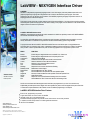
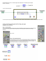
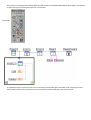
LabVIEW - NEXYGEN Interface Driver
LabVIEW®
LabVIEW is a fully featured programming language based on icons and images, produced by National Instruments. It is a
graphical programming language with a diagrammatic view of how the data flows through the program. This makes
programming very easy as data flow can be visualised. The LabVIEW programming language is expressed in the form of
simple graphical icons called block diagrams.
The program consists of two entry screens called the Control Panel and the Diagram. The Control Panel is the User Interface
and the Diagram represents the program flow chart. When creating a new program, the user interface is "built" first then the flow
diagram is drawn around the front panel items.
LabVIEW - NEXYGEN Interface Driver
AMETEK’s novel interface driver extends the modes available from LabVIEW to specifically control LLOYD INSTRUMENTS
and CHATILLON materials testing machines.
The LabVIEW - NEXYGEN Interface Driver is designed to allow Universities and Manufacturing organisations, who have
already standardised on LabVIEW to incorporate and control their materials testing systems using LabVIEW.
To programme a test with the LabVIEW - NEXYGEN Interface Driver the user has the option of using predefined test
procedures (Sub VI’s), which they may modify, or alternatively create their own test procedure from sctratch. The interface
driver provides 15 Sub VI’s(Virtual Instrument’s) that can be strung together to form a programme to perform a test:
SPECIFICATION
SS-MT-xxxx-0202
February 2002
SUB VI
FUNCTION
Break%
BreakSharp
Compression
Connect
Control
Error
Quit
Readings
ReleaseConsole
ReturnToZero
Stage
StageHold
Tension
Values
Zero
End the Stage or StageHold when the Load falls BY X% of Max Load
End the Stage or StageHold when the Load quickly falls to zero
Select Compression Mode
Creates the Console Object and connects it to the machine
Allow the Software Console to Move the Machine
Report any errors from the Software Console
Closes the Software Console
Reports the Last Load and Last Extension Reading
Releases the Console Object
Moves the Machine to its "Zero" Position
Moves the Machine to the specified Limit at the Specified Speed
Moves and Holds the Machine at the specified Limit for the Specified Time
Select Tension Mode
Reports ALL the Load and Extension Readings since it was last Run
Sets the Machines "Zero" Position and sets the Load Reading to Zero
Sub VI’s are summarised schematic diagrams which have been pre-programmed for you. Sub VI’s cannot be used
independantly, but when placed on the diagram and ‘wired’ together, they make a valid and logical test sequence. Each Sub
VI contains the required references to the software console so additional programming is not required.
LabVIEW - NEXYGEN Interface Driver Features:
www.ametek.com
www.lloyd-instruments.co.uk
www.chatillon.com
www.davenport-instruments.co.uk
Ease of use, programming via pictures
Logical and intuitive for current users of LabVIEW
Includes 15 Sub VI’s for programming tests
Predefined example programs are provided in the manual which can be easily modified
3 software consoles are provided for controlling different machines
ISO TickIT Accreditation
AMETEK and CHATILLON are registered trademarks of AMETEK,Inc
LLOYD INSTRUMENTS, NEXYGEN and ONDIO are trademarks of AMETEK, Inc.
Copyright 2001, by AMETEK, inc.
By double clicking on any Sub VI a VI schematic diagram will be revealed, which is summarised by the block diagram.
Example: Control Sub VI
Control VI Schematic Diagram.
The user need never see the schematic diagram unless he wishes to alter the machine operation or program a testing sequence from scratch.
Creating a Test Program Using the Sub VI’s is Easy and Logical
Example: Pull to Limit Test
Step 1 - The User Interface
Within the User Interface right click the mouse to display the CONTROL palette (shown below) and select the Numeric
Icon. Choose the Gauge option and label the Gauge ‘Load’. Do the same again and label the second Gauge
‘Extension’.
Step 1: Numeric
Step 2 - The Programming Interface
Load and Extension are now also shown on the Programming Interface. To develop the rest
of the program right click the mouse for the FUNCTIONS palette (shown to the right). Using
the FUNCTIONS palette you can select the appropriate Sub VI’s to develop a program. To
create a Pull to Limit Test you would select the following Sub VI’s:
Step 2: Select a VI
In order for the test to run the Sub VI’s need to be strung together correctly. To do this you use the CONNECT WIRE cursor within the TOOLS
palette which looks like a bobbin.
CONNECT WIRE cursor
Move the cursor over the Icons and their connectors will be identified. By doing this you can simply join the top corners of the Icons
appropriately as shown below.
To set the parameters of the test right click over the bottom left corner of the STAGE Icon to select ‘CREATE, CONSTANT’ and change the
travel to 100mm. Right click over the bottom right corner of the STAGE Icon to select ‘CREATE CONSTANT’ to change the speed to
200mm/min, for example.
To loop sectioons of the diagram select ‘STRUCTURES’ and ‘WHILE LOOP’ from the FUNCTIONS palette (as shown below). In this example
you would draw a loop around the bottom three Icons to connect them.
STRUCTURES
To complete the program you would move the cursor over the small Icon in the bottom right of the ‘WHILE LOOP’ and right click to select
‘STOP IF TRUE’. When run this program would now move the machine to 100mm at 200mm/min, then stop the machine.
Ordering Information
Order No.
Description
40/0733
01/3128
NEXYGEN™ Software consoles incorporating LabVIEW - NEXYGEN Interface Driver
LabVIEW - NEXYGEN Interface Driver User Manual
Consoles provided:
System Requirements (Minimum)
LR Console
EZ Console
TCD Console
Predifined Example Programmes:
•
•
•
•
•
•
The following predefined example programmes are provided in the
manual, these can be modified to suit individual user needs:
ISO TickIT Accreditation
for LF500, LRX and LR Series machines
for LFPlus, LRXPlus, LRPlus and EZ Series machines
for TCD Series machines
Creating a Pull to Limit Test
Creating a Pull to Break Test
Creating a Single Cycle Test
Creating a Multiple Cycle Test
Plotting Data on an XY Graph
Storing Data to a file
Creating a Creep Test
Creating a Relaxation Test
Stopping a Stage Using and External Switch
Stopping a Stage by a Load Value
Pentium 2® Processor, 400MHz
128MB RAM
250MB Hard Disk Space
1 Free COM Port, with 16550 UART
CD ROM Drive (For Installation)
Monitor, with resolution 1204 x 768 or higher
The LabVIEW - NEXYGEN Interface Driver has been developed
and endorsed with TickIT approval as part of AMETEK LLOYD
INSTRUMENTS’ BS EN ISO 9001:1994 registration.
Machine Compatibility:
Easy Test (EZ) Series machine with program V3.1 or later.
LFPlus, LRXPlus or LRPlus machine with program V3.1 or later.
LR Series machine which is fitted with EPROM's Version V7.5 or later.
LRX/LF500/TA500 machine which is fitted with EPROM's Version V2.11 or later.
Chatillon TCD frame.
LabVIEW™ Compatibility:
The LabVIEW - NEXYGEN Interface Driver is to be used with LabVIEW version
6i or later.
TEST AND CALIBRATION INSTRUMENTS
UK
Lloyd Instruments Ltd
Forum House
12 Barnes Wallis Road
Segensworth East, Fareham
Hampshire, PO15 5TT
UK
Tel: +44 (0)1489 486 399
Fax: +44 (0)1489 885 118
America
AMETEK TCI Division
8600 Somerset Drive
Largo
Florida 33773
USA
Tel: +1 (727) 536 7831
Fax: +1(727) 539 6882
Far East
Lloyd Instruments
Far East Representative Office
No7 Sherwood Place
Alexander Heights
6064 Perth
WESTERN AUSTRALIA
Tel: +61 8 9343 5725
Fax: +61 8 9343 5723
France
Lloyd Instruments SA
3 avenue des Coudriers
Zone d’activite de l’observatoire
78180 Montigny-Le-Bretonneux
FRANCE
Germany
AMETEK Precision Instruments
Europe GmbH
Rudolf-Diesel-Straße 16
D-40670 Meerbusch
GERMANY
Tel: +33 (0) 1 30 57 47 74
Fax: +33 (0) 1 30 57 50 33
Tel: +49 (0)2159 9136-70
Fax: +49 (0)2159 9136-80
email: [email protected]
www.lloyd-instruments.co.uk
Information within this document is subject to change without notice.
ISO 9001
Manufacturer


![SCP-306 USER MANUAL [E]](http://vs1.manualzilla.com/store/data/005768075_1-e94b2c34af8c4fc236a4fe3d8d7a36c2-150x150.png)