1
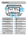
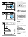
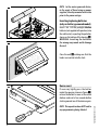
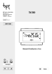
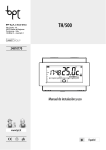
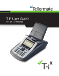
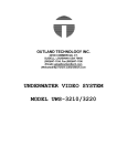
TA/500
24811390
Installer and user manual
www.bpt.it
EN
English
General Notes
•Read the instructions carefully before beginning the installation and carry out the actions as specified by
the manufacturer.
•The installation, programming, commissioning and maintenance of the product must only be carried out
by qualified technicians, properly trained in compliance with the regulations in force, including health and
safety measures and the disposal of packaging.
•The installer must ensure that the information for the user, where there is any, is provided and delivered.
•Before carrying out any cleaning or maintenance operation, disconnect the devices from the power supply.
•The equipment must only be used for the purpose for which it was expressly designed.
•The manufacturer declines all liability for any damage as a result of improper, incorrect or unreasonable use.
•Warning: danger of explosion if the batteries are replaced with others of the wrong type.
•Once batteries are dead they must not be thrown away with unsorted waste but collected separately and
sent for suitable recycling.
TA/500EN 24811390 31-10-14
DISPOSAL - Make sure the packaging material is not disposed of in the environment, but rather disposed
of in compliance with the laws in effect in the country in which the product is being used.
At the end of the product’s life cycle, make sure it is not disposed of in the environment. The equipment
must be disposed of in compliance with current laws and its components recycled where possible. The
components that should be recycled are marked with the material’s ID marker.
EC Declaration - BPT S.p.A. a Socio Unico declares that this device complies with directives 2004/108/EC
and 2006/95/EC. Originals upon request.
2
Description of device
④ ⑨ ⑤
⑥ ⑦
⑧
①
②
③
⑬
⑰
⑭
⑪
⑱
⑯
⑫
⑩
Button to change thermal zone mode
⑪
Button to access device set-up
③
Battery charge status
(only on battery-powered version)
Window contact active
(only on battery-powered version)
The arrow indicates
the active user profile
⑫
Navigation buttons
④
ECO program in operation
⑬
System in heating mode
⑤
NIGHT program in operation
⑭
Boiler in operation
⑥
Thermal zone excluded from control
⑮
System in cooling mode
⑦
Screen lock on
⑯
Cooler in operation
⑧
Remote activation in progress
(only on battery-powered version)
⑰
System off
⑨
Manual programming in operation
⑱
System in frost-protection mode
①
②
TA/500EN 24811390 31-10-14
⑩
⑮
3
Installation
Install the unit in a position which is suitable for correct room temperature measurement, for example
on an internal wall. Avoid installation in alcoves,
behind doors or curtains, or near heat sources.
A
Wall-mounted installation
B
①
•Open the device by pressing the button on the
bottom B, with your finger ① for the battery-powered model or with a small screwdriver
② for the model powered by mains electricity.
C
•R emove the terminal block cover and fasten
the back of the unit either to the wall or inside
the recessed back-box C using the screws and
expansion plugs supplied.
•After making the electrical connections shown
below, replace the terminal block cover.
WARNING. install the device on flat surfaces and
do not over-tighten the screws.
4
TA/500EN 24811390 31-10-14
②
D
N L
VALVE
OPEN
M
CLOSED
U2
E
N L
LOAD
The connections are made according to
the type of equipment controlled by the
programmable thermostat.
Figures D and E refer to the
mains-powered programmable thermostat but are also valid for the battery-powered version, only for the part
relating to the relay contacts.
Figure F illustrates possible uses of the
terminals
present only on the
battery-powered model.
① Connection through remote activation (maximum distance 20 metres),
② Connection through magnetic
contact (maximum distance 20 metres),
③ Connection by remote probe (OH/STI,
OH/STE, maximum distance 10 metres),
KEY
Mains power supply wires
N = neutral – L = live
U1
Relay contacts
NC = normally closed contact
C = common
NO = normally open contact
F
Loads
U1 = burner, circulation pump, solenoid
valve, etc.
U2 = motorised valve
①
②
TA/500EN 24811390 31-10-14
Electrical connections
Inputs for remote control
(only on battery-powered model)
③
NOTE. Before connecting, refer to the
technical documentation of the device
to be controlled.
5
G
NOTE. In the mains-powered device,
in the event of there being no power
supplied, the relay remains in the state
prior to the power outage.
Inserting/replacing batteries
(only on battery-powered model)
H
Insert 2 AA 1.5V LR6 penlight alkaline
batteries (not supplied with purchase) into
the relative slot, respecting the polarities
shown on the bottom of the housing G.
WARNING. Inserting the batteries
the wrong way round could damage
the unit.
Close the unit H making sure that the
hooks are inserted into the slots.
I
Device reset
NOTE. This operation does NOT lead to
any programming being deleted.
6
TA/500EN 24811390 31-10-14
If necessary lightly press the button
inside the opening shown in figure I;
release the button as soon as the screen
darkens and wait a few seconds before
starting normal use of the device again.
Operation of device
When first turned on, A the programmable thermostat is in heating mode
is on; the right-hand side of the display shows the temperature measured.
and the Comfort program
NOTE. When the device is in stand-by, the first touch on the screen switches on the back-lighting and
does not carry out any command.
Setting date and time
Touch the clock area A and keep touching it
until the minutes start to flash B.
A
B
Use the
arrows to set the desired
value and the
button to move on to
adjusting the time.
Press the
button to see and set the
following, using the arrows:
- Minutes
- Hour
- Year
- Month
- Day
- Format of time displayed (12 or 24 hr)
- Enable/disable automatic change to and
from daylight savings time C.
buttons
Prolonged pressing of the
takes you to the desired value more quickly.
TA/500EN 24811390 31-10-14
C
Note. If no button is pressed for a few
seconds, the device goes back to the
main screen and the values inserted are
considered valid.
7
Changing the system's operating mode
A
Touch the area shown in figure A and
continue touching until a beep indicates
the mode is changed between:
System in Heating mode
System in Cooling mode
System off
System in Frost-protection mode
When the system is off ( ), the image in
figure B is displayed on the screen for a
few seconds, to indicate that the system is off;
Then the temperature detected will reappear.
B
C
When the system is put into frost-protection mode C ( ) the arrows let you
set the minimum ambient temperature
tolerated; Then the temperature detected
will reappear.
Note. Programmable frost-protection temperature: Minimum 3.0°C – Maximum 16.0°C.
Choosing a heat management program
In Cooling mode
Comfort
24.0 °C
26.0 °C
Eco
28.0 °C
Night
E
8
TA/500EN 24811390 31-10-14
D
By pressing the
button in figure D
it is possible to choose 3 levels of desired
temperature.
The three pre-set temperature levels are:
In Heating Mode
Comfort
20.0 °C
18.0 °C
Eco
16.0 °C
Night
Each time it is pressed, it shows the program
in activation and the pre-set desired temperature for a few seconds EF; then the current
time and temperature detected reappear.
F
G
Exclusion from thermal control
D
To activate this mode press button
until the icon appears D.
If the system is in "Heating" mode, the
frost-protection function remains on.
The frost-protection temperature set
G is shown for a few seconds, then the
current time and temperature detected are
displayed H.
If the system is in "Cooling" mode, the
control will be totally excluded.
H
Manually forcing the desired temperature
With any heating management program
active I (Eco, Comfort, Night), press the
arrows J to change the desired
temperature set.
TA/500EN 24811390 31-10-14
I
The new desired temperature is shown in
place of the temperature detected J, any
active program icon disappears to leave
space for the icon.
J
After the video time-out the current time
and temperature detected reappear.
9
Other information that can be
displayed on the main page
A
B
By briefly pressing on the area where the
temperature detected is displayed A,
the objective temperature (set point) is
displayed in place of the time B.
Press the highlighted area again A to go
back to the previous display mode.
Displaying the temperature detected
by an external probe
If an external probe, set as secondary, is
connected to the device, by briefly pressing
on the area where the temperature detected
is displayed A, the temperature detected
by the external probe is displayed in place
of the time C.
Press again on the area where the temperature detected by the main probe is displayed
to return to the previous display mode.
C
Changing the pre-set temperature levels
With any heat management program active
(Eco, Comfort, Night), press and hold down
the area highlighted in figure D until the
screen in figure E appears.
Press on the
arrows E to change
the desired temperature for the program
displayed.
Press and hold down the area highlighted
in figure E to display the next program to
be changed F.
E
10
TA/500EN 24811390 31-10-14
D
Proceed as explained before to make changes to the programming and do the same for
all the pre-set programs
Note. The changes are effective for programming relating to the active User.
F
Unlocking the screen
If screen lock is enabled G, pressing on any
sensitive area of the screen gives access to
the window shown in figure H.
G
TA/500EN 24811390 31-10-14
H
The first number flashes; use the
arrows to choose the first digit of the code,
and the arrow to move on to the next
digit; once all the digits of the code have
been entered, press the
button to
confirm what has been entered and the
screen unlocks; the unlocking is valid until
the next time the screen times out.
11
Configuration of general parameters of the device
When the device is in "Exclusion from thermal control" mode (see page 9), holding down the
button A gives access to the device's configuration screens B.
Note. After accessing the configuration screens, pressing the button lets you display the parameters
to be configured in sequence, the
button lets you exit the configuration window and go back to the
screen in figure A.
Changing User profile
The device can manage the thermal preferences of two User profiles.
For each user profile different "Comfort",
"Eco" and "Night" programs can be created
for the Heating and Cooling modes.
A
Use the
arrows to change the active
User profile B.
Press the button to move on to the next
parameter to be configured.
B
Enabling the screen lock
The factory settings do not provide any
protection from changes for the device C.
To leave this setting unchanged and move on
to the next parameter, press the button.
If you want to protect the device from
unwanted changes to programming, use the
arrows to enable the screen lock D.
D
12
Press the button to access the window
that lets you set the code (password) that
must be entered to unlock the device.
TA/500EN 24811390 31-10-14
C
E
The first number flashes E; use the
arrows to enter the first digit of the
code, and the arrow to move on to the
next digit; pressing button at any time
means the code entered is considered valid
and you move on to the next parameter to
be configured.
Changing the calibration of the temperature detection probe
If the location of the device does not permit suitable detection of the temperature, it is possible to change
the temperature detected by ±3 °C with increases of a tenth of a degree.
Use the
arrows F to change the data
detected by the desired value and press the
button to move on to the next parameter
to be configured.
F
TA/500EN 24811390 31-10-14
Setting the type of heat
management algorithm
G
The device lets you choose the type of
algorithm to apply for the management of
the system between:
•Differential
•Proportional Integral
H
Differential Algorithm G
If, on screen G, using the
arrows, the
differential algorithm type has been chosen,
press the button to customise the value
of the differential, using the
arrow H.
Note. The range of adjustment goes from
0 to 1°C.
13
Temperature
OFF
This function is useful for environments that
are particularly hard to air condition, with
extreme variations in external temperature
and commands the switching on of the
system as shown in figure I.
Set-point
+ differential
Set-point
ON
ON
Time
Set-point
– differential
I
Proportional Integral Algorithm
If, on screen G, using the
arrows,
the proportional integral algorithm type
has been chosen, the screen in figure J
is displayed.
1h
J
Press the button to be able to access
the screen in figure K which, using the
arrows, lets you choose one of the 4
available programs (see table).
The first 3 (P1 - P2 - P3) cannot be changed.
K
Program P4 can be made up as required.
Press the button in figure K to be able
to enter the duration of a cycle, using the
arrows L.
Press the button in figure L to be able
to enter the minimum on time, using the
arrows M.
M
14
TA/500EN 24811390 31-10-14
L
ONPress the button in figure M to be able
to enter the value of the proportional band,
using the
arrows N.
ON
Press the button to move on to the next
parameter to be configured.
N
Temperature
1h
Set-point
Time
Prog.
Cycle duration Minimum ON time Proportional
(minutes)
(minutes)
Range
P1
10
1
P2
P3
P4
5
1
20
2
from 5 to 40 from 1 to 5
1.5 °C
1.5 °C
1.5 °C
from 1 °C to 3 °C
Type of system
Base for gas burner, convector heaters, zone valves,
aluminium radiators
Electric radiators
Radiant or underfloor systems, cooling
Setting the unit of measurement
for the temperature
Choose the unit of measurement for the
temperature using the
arrows O.
Press the button to move on to the next
parameter to be configured.
TA/500EN 24811390 31-10-14
O
15
Use of terminals
(only on battery-powered model)
Choose the function associated with the terminals
using the
arrows A from:
= compatible remote probe
A
= telephone contact
= window contact
Choice of main probe
(only on battery-powered model)
If you have chosen to connect to the terminals
an external probe (
),
pressing the button will make the screen
in figure B appear.
B
Using the
arrows you can choose
the function that the external probe must
carry out:
= Secondary probe
= Main probe
Note. If the external probe is set as the main probe, the temperature it detects is shown on the display
and used as a reference for the operation of the heating/cooling system. The temperature detected by
the device's internal probe cannot be seen on the display.
Remote activation via phone (only on battery-powered model)
If you have chosen to connect to the terminals
a suitable telephone interface
C ( ), pressing the button brings up
the screen in figure D.
C
16
TA/500EN 24811390 31-10-14
By connecting a suitable telephone interface to the terminals
you can activate the "Comfort" program
for the Heating or Cooling modes, in the following ways:
Activation - Close the contact
for at least 5 seconds. The icon comes on on the display.
Deactivation - Close the contact
for at least 5 seconds. The icon disappears from the display
and the device goes back to the operating mode prior to activation. Deactivation can also be achieved by
manually changing the operating program.
Using the
arrows you can set the operating mode that the device must take up
on receipt of the remove phone command.
= Heating
= Cooling
D
Press the button to move on to the next
parameter to be configured.
Window contact
(only on battery-powered model)
E
If you have chosen to connect to the terminals
a window contact E ( ),
you can set it so that the thermal zone is
turned off thirty seconds after the window
in which the contact is fitted is opened.
Note. When the window is closed again, the thermal zone goes back to the mode prior to its activation.
Press the button to move on to the next parameter to be configured.
Back-lighting of display
(only on mains-powered model)
F
Using the
arrows F, choose whether
the back-lighting should always be on (ON)
or only when the display is touched.
Press the button to move on to the next
parameter to be configured.
TA/500EN 24811390 31-10-14
Adjusting display brightness
Change the screen brightness using the
arrows G.
OO= Back-lighting always off.
G
Press the button to move on to the next
parameter to be configured.
17
Buttons beep
Choose whether to activate/deactivate the
buttons beep using the
arrows A.
Press the button to move on to the next
parameter to be configured.
A
Hours of activity counter
The screen in figure B shows the device's
hours of activity.
To reset the counter to zero, press it for a long
time in the area highlighted in the figure.
Press the button to move on to the next
parameter to be configured.
B
Firmware version
The screen in figure C shows the number of
the firmware version installed on the device.
Press the button to move on to the next
parameter to be configured.
Replacing batteries
(only on battery-powered model)
D
The flashing
icon on the display D
indicates that the batteries must be replaced
within about 1 month.
Note: To save the remaining energy, the
display's back-lighting is deactivated.
The icons
and
indicate that the
battery charge is not enough to manage the
thermal zone, which is therefore excluded
from control E.
WARNING. Failure to replace the batteries in
time may cause damage to the heating system
(anti-freeze protection is no longer guaranteed).
E
18
TA/500EN 24811390 31-10-14
C
Note. In all models of the device, the temporary lack of power caused by a mains power outage or replacing
the battery, does NOT lead to any programming being deleted.
TA/500EN 24811390 31-10-14
Technical features
Battery-powered TA500
Mains-powered TA500
•Power supply: 2 alkaline LR6 penlight AA 1.5V
batteries (not supplied).
•Battery life: More than 1 year.
•Time available for replacement of batteries:
1 minute
•Relay: max. voltage 250 V, max. current 5A with
resistive load (2A with inductive load).
•Type of action: 1B-U.
•Available contacts: 1 NA-NC switch contact.
Available inputs: 1 input for remote control
or for connection of external probe
(maximum cable length 10 metres).
•Temperature range of external probe: from
–30 °C to +60°C.
•Accuracy of internal probe: ≤ ±0.3°C.
•Resolution temperature reading: 0.1°C.
•Accuracy of clock: maximum error ±1 sec/day.
•Range of adjustment: from +3°C to +35°C.
•Protection rating: IP30.
•Operating temperature: from 0 °C to +40 °C.
•Maximum operating relative humidity: 93%
(without condensation).
•Dimensions: 140x92x24.5 mm
•Room temperature measurement interval:
15 seconds.
•Electrical insulation: Class II, reinforced
between accessible parts and terminals,
•Maximum control unit temperature: T40
•Power supply: 230 Vac 50/60Hz
•Consumption: 16mA.
•Autonomous life without power supply:
about 10 hrs.
•Relay: max. voltage 250 V, max. current 5A with
resistive load (2A with inductive load).
•Type of action: 1B-U.
•Available contacts: 1 NA-NC switch contact.
•Accuracy of internal probe: ≤ ±0.5 °C.
•Resolution temperature reading: 0.1°C.
•Accuracy of clock: maximum error ±1 sec/day.
•Range of adjustment: from +3°C to +35°C.
•Protection rating: IP30.
•Operating temperature: from 0 °C to +40 °C.
•Maximum operating relative humidity: 93%
(without condensation).
•Dimensions: 140x92x24.5 mm
•Room temperature measurement interval:
15 seconds.
•Electrical insulation: Class II, reinforced
between accessible parts and terminals,
•Maximum control unit temperature: T40
19
20
TA/500EN 24811390 31-10-14