1
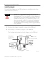
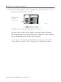
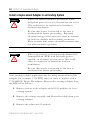
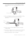
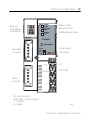
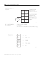
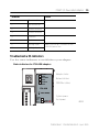
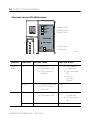
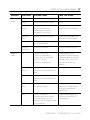
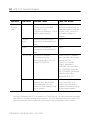
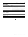
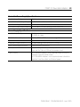
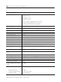
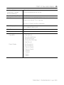
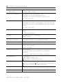
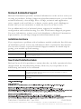
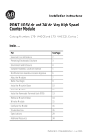
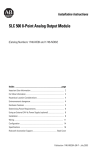
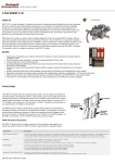
Installation Instructions
POINT I/O DeviceNet Adapter
Catalog Numbers 1734-ADN, 1734-ADNX
Inside…
For This Topic
See Page
Important User Information
2
Preventing Electrostatic Discharge
3
Environment and Enclosure
4
About This Manual
5
About the Adapter
5
For More Information
5
Install the Adapter
6
Install a Replacement Adapter in an Existing System
10
Wire the Adapter
12
Troubleshoot with Indicators
15
North American Hazardous Location Approval
19
European Hazardous Location Approval
20
Specifications
21
Rockwell Automation Support
28
Publication 1734-IN026A-EN-P - April 2005
2 POINT I/O DeviceNet Adapter
Important User Information
Solid state equipment has operational characteristics differing from those of
electromechanical equipment. Safety Guidelines for the Application, Installation and
Maintenance of Solid State Controls (Publication SGI-1.1 available from your local Rockwell
Automation sales office or online at http://literature.rockwellautomation.com) describes
some important differences between solid state equipment and hard-wired
electromechanical devices. Because of this difference, and also because of the wide variety
of uses for solid state equipment, all persons responsible for applying this equipment must
satisfy themselves that each intended application of this equipment is acceptable.
In no event will Rockwell Automation, Inc. be responsible or liable for indirect or
consequential damages resulting from the use or application of this equipment.
The examples and diagrams in this manual are included solely for illustrative purposes.
Because of the many variables and requirements associated with any particular installation,
Rockwell Automation, Inc. cannot assume responsibility or liability for actual use based on
the examples and diagrams.
No patent liability is assumed by Rockwell Automation, Inc. with respect to use of
information, circuits, equipment, or software described in this manual.
Reproduction of the contents of this manual, in whole or in part, without written permission
of Rockwell Automation, Inc., is prohibited.
Throughout this manual, when necessary, we use notes to make you aware of safety
considerations.
WARNING
IMPORTANT
ATTENTION
Identifies information about practices or circumstances that can cause an explosion in a
hazardous environment, which may lead to personal injury or death, property damage, or
economic loss.
Identifies information that is critical for successful application and understanding of the
product.
Identifies information about practices or circumstances that can lead to personal injury or
death, property damage, or economic loss. Attentions help you:
• identify a hazard
• avoid a hazard
• recognize the consequence
SHOCK HAZARD
Labels may be located on or inside the equipment (e.g., drive or motor) to alert people
that dangerous voltage may be present.
BURN HAZARD
Labels may be located on or inside the equipment (e.g., drive or motor) to alert people
that surfaces may be dangerous temperatures.
Publication 1734-IN026A-EN-P - April 2005
POINT I/O DeviceNet Adapter 3
ATTENTION
Preventing Electrostatic Discharge
This equipment is sensitive to electrostatic
discharge, which can cause internal damage and
affect normal operation. Follow these guidelines
when you handle this equipment:
• Touch a grounded object to discharge
potential static.
• Wear an approved grounding wriststrap.
• Do not touch connectors or pins on
component boards.
• Do not touch circuit components inside the
equipment.
• If available, use a static-safe workstation.
• When not in use, store the equipment in
appropriate static-safe packaging.
Publication 1734-IN026A-EN-P - April 2005
4 POINT I/O DeviceNet Adapter
ATTENTION
Environment and Enclosure
This equipment is intended for use in a Pollution
Degree 2 industrial environment, in overvoltage
Category II applications (as defined in IEC
publication 60664-1), at altitudes up to 2000 meters
without derating.
This equipment is considered Group 1, Class A
industrial equipment according to IEC/CISPR
Publication 11. Without appropriate precautions,
there may be potential difficulties ensuring
electromagnetic compatibility in other environments
due to conducted as well as radiated disturbance.
This equipment is supplied as “open type”
equipment. It must be mounted within an enclosure
that is suitably designed for those specific
environmental conditions that will be present and
appropriately designed to prevent personal injury
resulting from accessibility to live parts. The interior
of the enclosure must be accessible only by the use
of a tool. Subsequent sections of this publication
may contain additional information regarding
specific enclosure type ratings that are required to
comply with certain product safety certifications.
See NEMA Standards publication 250 and IEC
publication 60529, as applicable, for explanations of
the degrees of protection provided by different
types of enclosure. Also, see the appropriate
sections in this publication, as well as the
Allen-Bradley publication 1770-4.1 (“Industrial
Automation Wiring and Grounding Guidelines”), for
additional installation requirements pertaining to
this equipment.
Publication 1734-IN026A-EN-P - April 2005
POINT I/O DeviceNet Adapter 5
About This Manual
Use this manual as a guide to install the adapter.
The manual covers hardware installation and other information
related to get you started.
IMPORTANT
In this manual, we use 1734-ADN(X) to refer to both of
the following adapters:
• 1734-ADN POINT I/O DeviceNet Adapter
• 1734-ADNX POINT I/O DeviceNet Adapter with
Subnet Expansion
We use 1734-ADN to refer only to the 1734-ADN
adapter and 1734-ADNX to refer only to the
1734-ADNX adapter. We also refer to the 1734-ADN(X)
POINT I/O DeviceNet Adapter as the adapter.
About the Adapter
The 1734-ADN(X) POINT I/O DeviceNet Adapter is a communication
adapter for POINT I/O modules.
The adapter provides an interface for controlling and communicating
with POINT I/O modules on a DeviceNet network.
For More Information
For more detailed information about use of the adapter, refer to the
POINT I/O DeviceNet Adapter user manual, publication 1734-UM002.
It is available online at URL http://literature.rockwellautomation.com.
Publication 1734-IN026A-EN-P - April 2005
6 POINT I/O DeviceNet Adapter
Install the Adapter
To install the adapter on the DIN rail prior to installing other base
units, proceed as follows.
ATTENTION
POINT I/O is grounded through the DIN rail to
chassis ground. Use zinc-plated, yellow-chromated
steel DIN rail to assure proper grounding. The use
of DIN rail materials (e.g., aluminum, plastic, etc.)
that can corrode, oxidize, or are poor conductors,
can result in improper or intermittent grounding.
Secure DIN rail to mounting surface approximately
every 200 mm.
1. Position the adapter vertically in front of the DIN rail.
2. Press firmly to install the adapter on the DIN rail.
The locking mechanism locks the adapter to the DIN rail.
1734-ADN(X)
communication
interface
DIN rail
Orange
screw slot
31110-MC
Publication 1734-IN026A-EN-P - April 2005
POINT I/O DeviceNet Adapter 7
3. Insert the DeviceNet network plug and tighten the holding
screws.
DeviceNet
network
plug
Holding screw
Holding screw
31111-MC
WARNING
If you connect or disconnect the communication
cable with power applied to this module or any
device on the network, an electrical arc can
occur. This could cause an explosion in
hazardous location installations.
Publication 1734-IN026A-EN-P - April 2005
8 POINT I/O DeviceNet Adapter
4. Set the node address by pressing the + and - buttons on the
2-position thumbwheel switch.
Network node
address
thumbwheel
Module
Status
0 2
PointBus
Status
ControlNet A
Status
ControlNet B
Status
42510
42510
1734-ACNR
Valid physical settings range from 00 to 63.
You can also set the node address to some value between
64-99. In this case, you can change the adapter’s node address
via the RSNetWorx for DeviceNet software.
If you use a value between 64-99, at power-up you use the
node address stored in the adapter’s non-volatile memory.
Publication 1734-IN026A-EN-P - April 2005
POINT I/O DeviceNet Adapter 9
5. Slide the safety end cap to remove it.
This exposes the backplane and power interconnections.
ATTENTION
Do not discard the end cap. Use this end cap to
cover the exposed interconnections on the last
mounting base on the DIN rail. Failure to do so
could result in equipment damage or injury from
electric shock.
Safety
end
cap
31112-MC
Publication 1734-IN026A-EN-P - April 2005
10 POINT I/O DeviceNet Adapter
Install a Replacement Adapter in an Existing System
WARNING
When you insert or remove the module while
backplane power is on, an electrical arc can occur.
This could cause an explosion in hazardous
location installations.
Be sure that power is removed or the area is
nonhazardous before proceeding. Repeated
electrical arcing causes excessive wear to contacts
on both the module and its mating connector.
Worn contacts may create electrical resistance that
can affect module operation.
WARNING
When you connect or disconnect the Removable
Terminal Block (RTB) with field-side power
applied, an electrical arc can occur. This could
cause an explosion in hazardous location
installations.
Be sure that power is removed or the area is
nonhazardous before proceeding.
Your existing control application may be using another DeviceNet
adapter (for example, 1734-PDN) that you want to replace with a
1734-ADN(X) DeviceNet adapter. Remove the existing adapter from
the DIN rail as follows.
1. Remove power to the adapter and all I/O modules in your
existing system.
2. Remove the wiring assembly and DeviceNet cable from your
existing adapter.
3. Remove the adjacent I/O module.
Publication 1734-IN026A-EN-P - April 2005
POINT I/O DeviceNet Adapter 11
For information about how to remove POINT I/O modules
from the DIN rail, see the associated publications for those
modules.
RTB removal handle
42511
4. Use a small-bladed screwdriver to rotate the DIN rail locking
screw to a vertical position and release the locking
mechanism.
42417
5. Pull the adapter off of the DIN rail to remove it from the
existing system.
6. Insert the new adapter into slot 0 using the steps described in
the Install the Adapter section of this manual on page 6.
7. Reattach I/O modules to the new adapter.
Publication 1734-IN026A-EN-P - April 2005
12 POINT I/O DeviceNet Adapter
Wire the Adapter
WARNING
WARNING
If you connect or disconnect the communications
cable with power applied to this module or any
device on the network, an electrical arc can occur.
This could cause an explosion in hazardous
location installations.
If you connect or disconnect wiring while the
field-side power is on, an electrical arc can occur.
This could cause an explosion in hazardous
location installations. Be sure that power is
removed or the area is nonhazardous before
proceeding.
Publication 1734-IN026A-EN-P - April 2005
POINT I/O DeviceNet Adapter 13
Network
node address
thumbwheel
Adapter
Status
DeviceNet
Status
Adapter status
PointBus
Status
PointBus/Subnet status
DeviceNet status
1734-ADN
DeviceNet
connector
System power
System
Power
Field
Power
Field power
NC
CHAS GND
Subnet
connector
C
V
NC = No Connection
CHAS GND = Chassis Ground
C = Common
V = Supply
NC
CHAS GND
C
V
42513
Publication 1734-IN026A-EN-P - April 2005
14 POINT I/O DeviceNet Adapter
Adapter/field power
12/24V dc
0
1
NC
NC
2
3
CHAS CHAS
4
V dc
Connect this dc
supply to the
internal power bus.
5
C
C
V
V
6
7
You cannot supply
power to the
adapter from the
DeviceNet power
supply.
42513
NC = No Connection
C = Common
DeviceNet
connection
CHAS = Chassis Ground
V = Supply
(Do not connect 120/240V ac power to this supply.)
Black
1
-V
Blue
2
CAN - Low
Bare
3
Shield
White
4
CAN - High
Red
5
+V
42514
Publication 1734-IN026A-EN-P - April 2005
POINT I/O DeviceNet Adapter 15
Terminal
Notes
0
No connection
Reserved
1
No connection
2
Chassis Ground
3
Chassis Ground
4
Common
5
Common
6
Voltage Input
7
Voltage Input
Apply 12/24V dc. Connects to the
internal power bus.
Troubleshoot with Indicators
Use the status indicators to troubleshoot your adapter.
Status indicators for 1734-ADN adapters
Adapter
Status
DeviceNet
Status
PointBus
Status
Adapter status
Network status
POINTBus status
1734-ADN
System
Power
Field
Power
System power
Field power
43932
Publication 1734-IN026A-EN-P - April 2005
16 POINT I/O DeviceNet Adapter
Status indicators for 1734-ADNX adapters
Adapter
Status
DeviceNet
Status
Subnet
Status
Adapter status
Network status
Subnet status
1734-ADNX
System
Power
Field
Power
Indicator
Indication
System
Power
Off
• Not active
• Field power is OFF.
• DC-DC converter
problem
Green
• System power is ON.
• DC-DC converter is
active (5V).
Off
• Not active
• Field power is OFF.
Field Power
Green
Probable Cause
System power
Field power
43933
Take This Action
• Check adapter
configuration.
• Turn field power
ON.
• Contact
Customer
Support.
None
Power is ON with 24V present. None
Publication 1734-IN026A-EN-P - April 2005
• Check adapter
configuration.
• Turn field power
ON.
POINT I/O DeviceNet Adapter 17
Indicator
Indication
Probable Cause
Take This Action
Adapter
Status
Off
No power is applied to device.
Power the adapter.
Green
Device is operating normally.
None
Flashing
Green
Device needs to be
commissioned because
configuration is missing,
incomplete, or incorrect
Check configuration and
recommission the adapter.
Flashing
Red
Recoverable fault is present.
Make sure the adapter does
not need a FLASH update.
Red
Unrecoverable fault may require
device replacement.
Replace the adapter.
Flashing
Red/Green
Device is in self-test.
Wait for self-test to finish.
Off
Device is not online.
- Device is autobauding .
- Device has not completed
dup_MAC_id test.
- Device is not powered.
Check adapter status
indicator to determine if you
need more time to complete
the dup_MAC_id test or if
you need to power the
adapter.
Flashing
Green
Device is online but has no
connections in the established
state.
None
Green
Device is online and has
connections in the established
state.
None
Flashing
Red
One or more I/O connections are
in timed-out states
Determine the cause of the
time-out. You may need to
increase the expected
packet rate.
Red
Critical link failure communication device failed.
Device detected error that
prevents it from communicating
on the network.
Make sure the device is
using the correct MAC ID
and baudrate.
Network
Status
Publication 1734-IN026A-EN-P - April 2005
18 POINT I/O DeviceNet Adapter
Indicator
Indication
Probable Cause
Take This Action
Subnet and
PointBus
Status
Off
Device is not online.
- Device has not completed
Dup_MAC_ID test.
- Device is not powered. - Check
module status indicator.
Check adapter status
indicator to determine if you
need more time to complete
the dup_MAC_id test or if
you need to power the
adapter.
Flashing
Green
Device is online but has no
connections in the established
state.
None
Green
Device is online and has
connections in the established
state.
None
Flashing Red
No scanlist is available.
I/O module is missing.
Max backplane MAC ID is not
set right (1734-ADNX).
Make sure all I/O modules
are connected and using the
correct MAC IDs.
Check “Cycling Node
Status” parameter in
RSNetWorx for DeviceNet.
For 1734-ADNX, terminate
the 1734-ADNX Subnet and
correctly set the Max
Backplane MAC ID.1
Red
Critical link failure communication device failed.
Device detected error that
prevents it from communicating
on the network.
Make sure an I/O module is
not using a MAC ID =0.
Make sure all backplane
modules are communicating
at the proper baudrate.
1Maxi(mum) Backplane MAC ID is an attribute for 1734-ADNX only. This value represents the highest
node address of a module residing on the backplane. The value must be greater than or equal to the
right-most backplane Subnet module, but less than that of any non-backplane Subnet module.
Publication 1734-IN026A-EN-P - April 2005
POINT I/O DeviceNet Adapter 19
North American Hazardous Location Approval
The 1734-ADN adapter has North American Hazardous Location
approval.
The following information applies when
operating this equipment in hazardous
locations:
Informations sur l’utilisation de cet équipement
en environnements dangereux:
Products marked “CL I, DIV 2, GP A, B, C, D” are suitable
for use in Class I Division 2 Groups A, B, C, D, Hazardous
Locations and nonhazardous locations only. Each product
is supplied with markings on the rating nameplate
indicating the hazardous location temperature code. When
combining products within a system, the most adverse
temperature code (lowest “T” number) may be used to
help determine the overall temperature code of the
system. Combinations of equipment in your system are
subject to investigation by the local Authority Having
Jurisdiction at the time of installation.
Les produits marqués “CL I, DIV 2, GP A, B, C, D” ne
conviennent qu’à une utilisation en environnements de Classe I
Division 2 Groupes A, B, C, D dangereux et non dangereux.
Chaque produit est livré avec des marquages sur sa plaque
d’identification qui indiquent le code de température pour les
environnements dangereux. Lorsque plusieurs produits sont
combinés dans un système, le code de température le plus
défavorable (code de température le plus faible) peut être
utilisé pour déterminer le code de température global du
système. Les combinaisons d’équipements dans le système
sont sujettes à inspection par les autorités locales qualifiées
au moment de l’installation.
EXPLOSION HAZARD -
WARNING
• Do not disconnect equipment unless
power has been removed or the area
is known to be nonhazardous.
• Do not disconnect connections to
this equipment unless power has
been removed or the area is known
to be nonhazardous. Secure any
external connections that mate to
this equipment by using screws,
sliding latches, threaded
connectors, or other means provided
with this product.
• Substitution of components may
impair suitability for Class I, Division
2.
• If this product contains batteries,
they must only be changed in an
area known to be nonhazardous.
RISQUE D’EXPLOSION –
AVERTISSEMENT
• Couper le courant ou s’assurer que
l’environnement est classé non
dangereux avant de débrancher
l'équipement.
• Couper le courant ou s'assurer que
l’environnement est classé non
dangereux avant de débrancher les
connecteurs. Fixer tous les
connecteurs externes reliés à cet
équipement à l'aide de vis, loquets
coulissants, connecteurs filetés ou
autres moyens fournis avec ce
produit.
• La substitution de composants peut
rendre cet équipement inadapté à une
utilisation en environnement de
Classe 1, Division 2.
• S’assurer que l’environnement est
classé non dangereux avant de
changer les piles.
Publication 1734-IN026A-EN-P - April 2005
20 POINT I/O DeviceNet Adapter
European Hazardous Location Approval
The 1734-ADN adapter has European Hazardous Location approval.
European Zone 2 Certification (The following applies when the product bears the
EEx Marking)
This equipment is intended for use in potentially explosive atmospheres as defined by
European Union Directive 94/9/EC.
DEMKO certifies that this equipment has been found to comply with the Essential Health
and Safety Requirements relating to the design and construction of Category 3 equipment
intended for use in potentially explosive atmospheres, given in Annex II to this Directive.
The examination and test results are recorded in confidential report No 03NK30347.
Compliance with the Essential Health and Safety Requirements has been assured by
compliance with EN 50021.
IMPORTANT
Observe the following additional Zone 2 certification
requirements.
This equipment is not resistant to sunlight or other sources
of UV radiation.
The secondary of a current transformer shall not be
open-circuited when applied in Class I, Zone 2
environments.
Equipment of lesser Enclosure Type Rating must be
installed in an enclosure providing at least IP54 protection
when applied in Class I, Zone 2 environments.
This equipment shall be used within its specified ratings
defined by Allen-Bradley.
Provision shall be made to prevent the rated voltage from
being exceeded by transient disturbances of more than 40%
when applied in Class I, Zone 2 environments.
Publication 1734-IN026A-EN-P - April 2005
POINT I/O DeviceNet Adapter 21
Specifications
Communication Interface Specifications
DeviceNet Communication Rate 125K bit/s (500m maximum)
250K bit/s (250m maximum)
500K bit/s (100m maximum)
DeviceNet Cable
Allen-Bradley part number 1485C-P1-Cxxx
Refer to publication NETS-SG001 for more information.
Module Location
Starter module - left side of 1734 system
Number of Powered Modules
63 maximum
Number of Integrated I/O
Channels
0
Number of I/O Points, Max.
504
DeviceNet Nodes with
Maximum I/O, Total
1
Node Address
1
I/O Module Capacity
63
DeviceNet Current
30mA
POINTBus Current
1000mA @5V dc + 5% (4.75...5.25V)
Publication 1734-IN026A-EN-P - April 2005
22 POINT I/O DeviceNet Adapter
Communications Interface Specifications (continued)
Expansion I/O Capacity
Up to 13 modules (13 times 75mA = 0.975, just under the
limit of 1.0A), based on POINTBus current requirements
The actual number of modules can vary. Add up the current
requirements of the modules you want to use to make sure
they do not exceed the amperage limit of the adapter. Total
expansion is up to 63 modules - 13 modules maximum with
the adapter. Add 1734-EP24DC modules for an additional
17 modules (or less based on current requirements), up to
63 modules maximum.
Cat. No.
1734-IB2
1734-IB4
1734-IB8
1734-IV2
1734-IV4
1734-OB2
1734-OB4
1734-OB8
1734-OB2E
1734-OB2EP
1734-OB4E
1734-OB8E
1734-OV2E
1734-OV4E
1734-OW2
1734-OX2
1734-IE2C
1734-OE2C
1734-IE2V
1734-OE2V
1734-IA2
1734-IM2
1734-OA2
1734-IJ2
1734-IK2
1734-IR2
1734-IT2I
1734-SSI
1734-VHSC5
1734-VHSC24
1734-232ASC
Publication 1734-IN026A-EN-P - April 2005
PointBus Current Requirements
75mA
75mA
75mA
75mA
75mA
75mA
75mA
75mA
75mA
75mA
75mA
75mA
75mA
75mA
80mA
100mA
75mA
75mA
75mA
75mA
75mA
75mA
75mA
160mA
160mA
220mA
175mA
110mA
180mA
180mA
75mA
POINT I/O DeviceNet Adapter 23
DeviceNet Power Supply Specifications
Input Voltage Rating
24V dc nominal
DeviceNet Input Voltage Range
11-25V dc DeviceNet specification
Input Overvoltage Protection
Reverse polarity protected
DeviceNet Power Requirements 24V dc (+4% = 25V dc max) @ 30mA maximum
Power Supply Specifications
Input Voltage Rating
24V dc nominal
10-28.8V dc range
Field Side Power Requirements
24V dc (+20% = 28.8V dc maximum) @ 400mA maximum
Inrush Current
6A maximum for 10ms
POINTBus Output Current
1A maximum @ 5V dc ±5% (4.75 - 5.25)
Input Overvoltage Protection
Reverse polarity protected
Interruption Protection
Output voltage will stay within specifications when input
drops out for 10ms at 10V with maximum load.
Power Supply
For 1734-ADN adapters, user supplied power should be
separate from DeviceNet power.
For 1734-ADNX adapters, user supplied power should be
separate from DeviceNet and Subnet power.
Publication 1734-IN026A-EN-P - April 2005
24 POINT I/O DeviceNet Adapter
General Specifications
Indicators
3 red/green status indicators
Adapter status
DeviceNet status
POINTBus status
2 green power supply status indicators:
System Power (POINTBus 5V power)
Field Power (24V from field supply)
Mounting Type
DIN-rail
Weight
0.26 kg (0.56 lb)
Module Location
Starter module - left side of 1734 system
Network Name
DeviceNet
Termination Type
None
Number of Nodes
1 maximum
Electronic Protection
No
Diagnostics
No
Enclosure Required
Yes
Power Consumption
8.1W @ 28.8V dc
Platform/Processor
Compatibility
1747; 1756; 1761; 1762; 1764; 1789; 1794
Power Dissipation
2.8W maximum @ 28.8V
Communication Interface
Type
Adapter
Device Type
Communication Interface
Thermal Dissipation
9.5 BTU/hr maximum @ 28.8V dc
Input Byte Capacity
248
Output Byte Capacity
248
Power Supply 24V Current
Load
400mA
Field Power Bus
Nominal Voltage
Supply Voltage Range
Supply Current
24V dc
10-28.8V dc range,
10A maximum
Publication 1734-IN026A-EN-P - April 2005
POINT I/O DeviceNet Adapter 25
Isolation Voltage
(Continuous - Voltage
Withstand Rating)
50V continuous
Test to withstand 800V dc for 60s
Operating Voltage Range
10...28.8V dc
Wire Size
14 AWG (2.5mm2) - 22 AWG (0.25mm2) solid or stranded,
copper wire rated at 75oC or greater
3/64 inch (1.2mm) insulation maximum
Wire Category1,2
1 on power ports
2 on communications ports
Wire Type
Copper
Terminal Base Screw Torque 5-7 pound-inches (0.5-0.6Nm)
Field Wiring Terminations
DeviceNet
Power Supply
1 - Black Wire-V
2 - Blue WireCAN Low
3 - Bare WireShield
4 - White WireCAN High
5 - Red Wire+V
0 - No Connection
1 - No Connection
2 - Chassis Ground
3 - Chassis Ground
4 - Common
5 - Common
6 - Supply
7 - Supply
Publication 1734-IN026A-EN-P - April 2005
26 POINT I/O DeviceNet Adapter
Dimensions Inches
(Millimeters)
3.0H x 2.16W x 5.25L
(76.2H x 54.9W x 133.4L)
Operational Temperature
IEC60068-2-1 (Test Ad, Operating Cold)
IEC60068-2-2 (Test Bd, Operating Dry Heat)
IEC60068-2-14 (Test Nb, Operating Thermal Shock)
-20...55oC (-4...131oF)
Storage Temperature
IEC60068-2-1 (Test Ab, Unpackaged Non-operating Cold)
IEC60068-2-2 (Test Bb, Unpackaged Non-operating Dry Heat)
IEC60068-2-14 (Test Na, Unpackaged Non-operating Thermal
Shock)
-40...85oC (-40...185oF)
Relative Humidity
IEC60068-2-30 (Test Db, Unpackaged Non-operating Damp
Heat)
5...95% noncondensing
Vibration
IEC60068-2-6 (Test Fc, Operating)
5g @ 10-500Hz
Shock Operating
Shock Non-operating
IEC 60068-2-27 (Test Ea, Unpackaged Shock) 30g
IEC 60068-2-27(Test Ea, Unpackaged Shock) 50g
Emissions
CISPR 11: Group 1, Class A
ESD Immunity
IEC6100-4-2
6kV contact discharges
8kV air discharges
Radiated RF Immunity
IEC 61000-4-3
10V/m with 1kHz sine-wave 80%AM from 30MHz to
2000MHz
10V/m with 200HZ 50% Pulse 100%Am at 900MHz
EFT/B Immunity
IEC 61000-4-4
+4kV at 5kHz on power ports
+2kV at 5kHz on communications ports
Surge Transient Immunity
IEC 61000-4-5
+1kV line-line (DM) and +2kV line-earth (CM) on power ports
+2kV line-earth (CM) on communications ports
Conducted RF Immunity
IEC61000-4-6
10Vrms with 1kHz sine-wave 80%AM from 150kHz to 80 MHz
Enclosure Type Rating
None (open-style)
Publication 1734-IN026A-EN-P - April 2005
POINT I/O DeviceNet Adapter 27
Certification3
1734-ADNX
(when product is marked)
CE European Union 89/336/EEC EMC Directive,
compliant with:
EN 61000-6-4; Industrial Emissions
EN 50082-2; Industrial Immunity
EN 61326; Meas./Control/Lab., Industrial
Requirements
EN 61000-6-2; Industrial Immunity
C-Tick Australian Radiocommunications Act, compliant with:
AS/NZS CISPR11; Industrial Emissions
DeviceNet compatible as certified by ODVA, Inc.
Certification3
1734-ADN
(when product is marked)
CE European Union 89/336/EEC EMC Directive,
compliant with:
EN 61000-6-4; Industrial Emissions
EN 50082-2; Industrial Immunity
EN 61326; Meas./Control/Lab., Industrial
Requirements
EN 61000-6-2; Industrial Immunity
C-Tick Australian Radiocommunications Act, compliant with:
AS/NZS CISPR11; Industrial Emissions
DeviceNet compatible as certified by ODVA, Inc.
c-UL-usUL Listed for Class I, Division 2 Group A,B,C,D
Hazardous Locations, certified for U.S. and Canada
EEX
European Union 94/9/EC ATEX Directive,
compliant with:
EN 50021; Potentially Explosive Atmospheres,
Protection “n” (Zone 2)
1
Use this Conductor Category information for planning conductor routing. Refer to Industrial
Automation Wiring and Grounding Guidelines, publication 1770-4.1.
2
Use this Conductor Category information for planning conductor routing as described in the
appropriate System Level Installation Manual.
3
See the Product Certification link at www.ab.com for Declarations of Conformity, Certificates, and
other certification details.
POINT I/O and POINTBus are trademarks of Rockwell Automation.
DeviceNet is a trademark of the Open DeviceNet Vendor Association.
Publication 1734-IN026A-EN-P - April 2005
Rockwell Automation Support
Rockwell Automation provides technical information on the web to assist you
in using its products. At http://support.rockwellautomation.com, you can find
technical manuals, a knowledge base of FAQs, technical and application
notes, sample code and links to software service packs, and a MySupport
feature that you can customize to make the best use of these tools.
For an additional level of technical phone support for installation,
configuration and troubleshooting, we offer TechConnect Support programs.
For more information, contact your local distributor or Rockwell Automation
representative, or visit http://support.rockwellautomation.com.
Installation Assistance
If you experience a problem with a hardware module within the first 24 hours
of installation, please review the information that's contained in this manual.
You can also contact a special Customer Support number for initial help in
getting your module up and running:
United States
1.440.646.3223 Monday – Friday, 8am – 5pm EST
Outside United States
Please contact your local Rockwell Automation representative for any
technical support issues.
New Product Satisfaction Return
Rockwell tests all of its products to ensure that they are fully operational when
shipped from the manufacturing facility. However, if your product is not
functioning and needs to be returned:
United States
Contact your distributor. You must provide a Customer Support case number
(see phone number above to obtain one) to your distributor in order to
complete the return process.
Outside United States
Please contact your local Rockwell Automation representative for return
procedure.
ö
Publication 1734-IN026A-EN-P - April 2005
PN 957955-25
Supersedes Publication 1734-IN007A-EN-P - August 2000, 1734-IN007B-EN-P - June 2001, and 1734-IN589A-EN-P - April 2003
Copyright © 2005 Rockwell Automation, Inc. All rights reserved. Printed in the U.S.A.