1
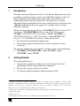
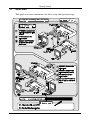
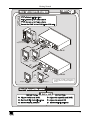
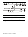
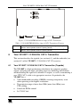
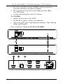
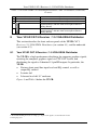
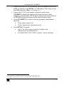
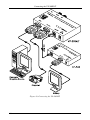
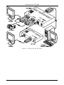
Kramer Electronics, Ltd.
USER MANUAL
Models:
VP-200XLT, XGA Line Amp / CAT 5 Transmitter
VP-200XLTHD, XGA Line Amp / CAT 5 Transmitter
VP-300T, 1:2 XGA DA/CAT 5 Transmitter
VP-5T, 1:4 VGA/UXGA Distributor/CAT 5 Transmitter
VP-5THD, 1:4 VGA/UXGA Distributor/CAT 5 Transmitter
VP-5R, CAT 5 Receiver / 1:5 VGA/UXGA Distributor
Contents
Contents
1
Introduction
2
Getting Started
2.1
Quick Start
3
Overview
3.1
About the Power Connect Feature
3.2
Shielded Twisted Pair (STP) / Unshielded Twisted Pair (UTP)
3.3
Recommendations for Achieving the Best Performance
4
Your VP-200XLT XGA Line Amp / CAT 5 Transmitter
5
VP-200XLTHD XGA Line Amp / CAT 5 Transmitter
6
Your VP-300T 1:2 XGA DA/ CAT 5 Transmitter
6.1
Your VP-300T 1:2 XGA DA/ CAT 5 Transmitter (Topside)
6.2
Your VP-300T 1:2 XGA DA/ CAT 5 Transmitter (Underside)
7
Your VP-5T/VP-5THD 1:4 VGA/UXGA Distributor / CAT 5
Transmitter
7.1
Your VP-5T/VP-5THD 1:4 VGA/UXGA Distributor / CAT 5 Transmitter
7.2
Your VP-5T/VP5THD (Underside)
8
Your VP-5R CAT 5 Receiver / 1:5 VGA/UXGA Distributor
8.1
Your VP-5R CAT 5 Receiver / 1:5 VGA/UXGA Distributor
8.2
Your VP-5R CAT 5 Receiver / 1:5 VGA/UXGA Distributor (Underside)
9
Connecting the VP-200XLT
10
Connecting the VP-300T
11
Connecting the VP-5T and the VP-5R
11.1
Wiring the CAT 5 LINE IN / LINE OUT RJ-45 Connectors
12
Technical Specifications
1
1
2
4
4
5
5
6
7
9
9
10
11
11
13
14
14
15
16
19
21
23
24
Figures
Figure 1: VP-200XLT XGA Line Amp / CAT 5 Transmitter
6
Figure 2: VP-200XLTHD XGA Line Amp / CAT 5 Transmitter
8
Figure 3: VP-200XLTHD XGA Line Amp / CAT 5 Transmitter
9
Figure 4: VP-300T 1:2 XGA DA/ CAT 5 Transmitter (Topside)
10
Figure 5: VP-300T 1:2 XGA DA/ CAT 5 Transmitter (Underside)
11
Figure 6: VP-5T/VP-5THD 1:4 VGA/UXGA Distributor / CAT 5 Transmitter
12
Figure 7: VP-5T/VP-5THD 1:4 VGA/UXGA Distributor / CAT 5 Transmitter (Underside)
13
Figure 8: VP-5R CAT 5 Receiver / 1:5 VGA/UXGA Distributor
15
Figure 9: VP-5R CAT 5 Receiver / 1:5 VGA/UXGA Distributor (Underside)
16
Figure 10: Connecting the VP-200XLT
18
Figure 11: Connecting the VP-300T
20
i
Contents
Figure 12: Connecting the VP-5T and the VP-5R
Figure 13: CAT 5 PINOUT
22
23
Tables
Table 1: VP-200XLT XGA Line Amp / CAT 5 Transmitter Features
7
Table 2: VP-200XLTHD XGA Line Amp / CAT 5 Transmitter Features
8
Table 3: VP-200XLTHD XGA Line Amp / CAT 5 Transmitter Features
9
Table 4: VP-300T 1:2 XGA DA/ CAT 5 Transmitter (Topside) Features
10
Table 5: VP-300T 1:2 XGA DA/ CAT 5 Transmitter (Underside) Features
11
Table 6: VP-5T 1:4 VGA/UXGA Distributor / CAT 5 Transmitter Features
13
Table 7: VP-5T/VP-5THD 1:4 VGA/UXGA Distributor / CAT 5 Transmitter (Underside)
Features
14
Table 8: VP-5R CAT 5 Receiver / 1:5 VGA/UXGA Distributor Features
15
Table 9: VP-5R CAT 5 Receiver / 1:5 VGA/UXGA Distributor (Underside) Features 16
Table 10: CAT 5 PINOUT
23
Table 11: Technical Specifications of the VP-200XLT (with 30m CAT 5 cable)
24
Table 12: Technical Specifications of the VP-200XLTHD (with 30m CAT 5 cable)
24
Table 13: Technical Specifications of the VP-300T (with 30m CAT 5 cable)
25
Table 14: Technical Specifications of the VP-5T/VP-5THD (with 60m CAT 5 cable)
25
Table 15: Technical Specifications of the VP-5R (with 30m CAT 5 cable)
26
ii
KRAMER: SIMPLE CREATIVE TECHNOLOGY
Introduction
1
Introduction
Welcome to Kramer Electronics! Since 1981, Kramer Electronics has been
providing a world of unique, creative, and affordable solutions to the vast
range of problems that confront the video, audio, presentation, and
broadcasting professional on a daily basis. In recent years, we have
redesigned and upgraded most of our line, making the best even better! Our
1,000-plus different models now appear in 11 groups1 that are clearly
defined by function.
Thank you for purchasing the Kramer: VP-200XLT XGA Line Amp/CAT 5
Transmitter, VP-200XLTHD XGA Line Amp / CAT 5 Transmitter,
VP-300T 1:2 XGA DA/ CAT 5 Transmitter, VP-5T, VP-5THD 1:4
VGA/UXGA Distributor / CAT 5 Transmitter, and/or VP-5R CAT 5
Receiver / 1:5 VGA/UXGA Distributor, which are ideal for:
Presentation and multimedia applications
Long range graphics distribution for schools, hospitals, security,
and stores
The package includes this user manual2, and one or more of the following:
VP-200XLT3/VP-200XLTHD3, and/or VP-300T3, and/or
VP-5T/HD4, and/or VP-5R4
2
Getting Started
We recommend that you:
Unpack the equipment carefully and save the original box and
packaging materials for possible future shipment
Review the contents of this user manual
Use Kramer high-performance high-resolution cables5
1 GROUP 1: Distribution Amplifiers; GROUP 2: Switchers and Matrix Switchers; GROUP 3: Control Systems;
GROUP 4: Format/Standards Converters; GROUP 5: Range Extenders and Repeaters; GROUP 6: Specialty AV Products;
GROUP 7: Scan Converters and Scalers; GROUP 8: Cables and Connectors; GROUP 9: Room Connectivity;
GROUP 10: Accessories and Rack Adapters; GROUP 11: Sierra Products
2 Download up-to-date Kramer user manuals from the Internet at this URL: http://www.kramerelectronics.com
3 With a power adapter
4 With a power cord
5 The complete list of Kramer cables is on our Web site at http://www.kramerelectronics.com
1
Getting Started
2.1
Quick Start
This quick start chart summarizes the basic setup and operation steps.
2
KRAMER: SIMPLE CREATIVE TECHNOLOGY
Getting Started
1
2
3
4
1
Computer
Graphics Source
VP-5T
2
Local
Display 1
Local
Display 4
4
VP-5R*
3
Display 1
Display 5
* Located up to 300ft (>100 meters)
away from the Computer Graphics
Source
3
Overview
3
Overview
This user manual describes the following products:
Kramer TOOLS VP-200XLT XGA Line Amp / CAT 5 Transmitter,
which accepts one computer graphics input and distributes the signal
to its high-density 15 pin “D” connector output, as well as
transmitting it over UTP cabling (CAT 5 or similar) to its appropriate
receiver, see section 4
Kramer TOOLS VP-200XLTHD XGA Line Amp / CAT 5
Transmitter, which accepts one computer graphics input and
distributes the signal to its high-density 15 pin “D” connector output,
as well as transmitting it over UTP cabling (CAT 5 or similar) to its
appropriate receiver, see section 5
Kramer TOOLS VP-300T 1:2 XGA DA/ CAT 5 Transmitter, which
is a distributor for computer graphics signals, accepting one input
and distributing the signal to its identical 2 outputs, as well as
transmitting it over CAT 5 UTP cable to its appropriate receiver, see
section 6
Kramer VP-5T/VP-5THD 1:4 VGA/UXGA Distributor / CAT 5
Transmitter, which is a distributor for computer graphics signals,
accepting one input, and distributing the signal to its identical 4
outputs, as well as transmitting it over CAT 5 UTP cable to its
appropriate receiver, see section 7
Kramer VP-5R CAT 5 Receiver / 1:5 VGA/UXGA Distributor, which
is a distributor for computer graphics signals, receiving the computer
graphics signal via CAT 5 UTP cable, and distributing the signal to 5
identical 15-pin HD outputs, see section 8
This section describes:
The power connect feature, see section 3.1
Using shielded twisted pair (STP) / unshielded twisted pair (UTP),
see section 3.2
Recommendations for achieving the best performance, see section
3.3
3.1
About the Power Connect Feature
The Power Connect feature applies as long as the cable can carry power. The
distance does not exceed 50m on standard CAT 5 cable, for longer distances,
heavy gauge cable should be used1.
1 CAT 5 cable is still suitable for the video/audio transmission, but not for feeding the power at these distances
4
KRAMER: SIMPLE CREATIVE TECHNOLOGY
Overview
For a CAT 5 cable exceeding a distance of 50m, separate power supplies
should be connected to the transmitter and to the receiver simultaneously.
3.2
Shielded Twisted Pair (STP) / Unshielded Twisted Pair (UTP)
We recommend that you use shielded twisted pair (STP) cable. There are
different levels of STP cable available, and we advise you to use the best
quality STP cable that you can afford. Our STP skew-free cable, Kramer
BC-SXTP, is intended for transmitting VGA signals. Our non-skew-free
cable, Kramer BC-STP, is intended for digital signals.
The compliance to electromagnetic interference was tested using STP
cables, therefore we recommend using those cables.
Although unshielded twisted pair (UTP) cable might be preferred for long
range applications, the UTP cable should be installed far away from electric
cables, motors and so on, which are prone to create electrical interference.
However, since the use of UTP cable may not conform to electromagnetic
standards, Kramer does not commit to meeting the standard with UTP cable.
3.3
Recommendations for Achieving the Best Performance
To achieve the best performance:
Connect only good quality connection cables, thus avoiding
interference, deterioration in signal quality due to poor matching,
and elevated noise- levels (often associated with low quality
cables)
Avoid interference from neighboring electrical appliances and
position your Kramer machines away from moisture, excessive
sunlight and dust
Caution – No operator-serviceable parts inside unit.
Warning – Use only the Kramer Electronics input power
wall adapter that is provided with this unit1.
Warning – Disconnect power and unplug unit from wall
before installing or removing device or servicing unit.
1 For example, part number 2535-000251
5
Your VP-200XLT XGA Line Amp / CAT 5 Transmitter
4
Your VP-200XLT XGA Line Amp / CAT 5 Transmitter
The VP-200XLT is a high-performance XGA line amp / CAT 5 transmitter
that accepts one computer graphics (XGA1) input, provides necessary
buffering and isolation, and distributes the signal to its high-density 15 pin
“D” connector output, as well as transmitting it over UTP CAT 5 cable to
its appropriate receiver.
In particular, the VP-200XLT has:
A transmission range of more than 300ft (more than 100m) over
UTP cabling
Video bandwidth exceeding 400MHz, ensuring transparency even
when operating at the highest resolutions
Output level control, and cable equalization, using two rotary
controls on the side panel of the machine
Figure 1 and Table 1 define the VP-200XLT:
Figure 1: VP-200XLT XGA Line Amp / CAT 5 Transmitter
1 The terminology XGA is used throughout this manual, where this implies any RGBHV signal on an 15-pin HD connector
having a resolution from VGA up to XGA
6
KRAMER: SIMPLE CREATIVE TECHNOLOGY
VP-200XLTHD XGA Line Amp / CAT 5 Transmitter
Table 1: VP-200XLT XGA Line Amp / CAT 5 Transmitter Features
#
Feature
1 12V DC
2 LINE OUT RJ-45 Connector
3
4
5
6
7
5
XGA OUT 15-pin HD Connector
INPUT 15-pin HD Connector
LEVEL Control knob
EQ. Control knob
ON LED
Function
+12V DC connector for powering the unit
1
Connects to the LINE IN RJ-45 connector on the TP-120 XGA Line
2
Receiver or the VP-5R CAT 5 Receiver / 1:5 VGA/UXGA Distributor
Connect to the XGA acceptor
Connect to the XGA source
Rotate to adjust the output signal level
Rotate to adjust the video EQ. (equalization) compensation
Illuminates when receiving power
VP-200XLTHD XGA Line Amp / CAT 5 Transmitter
The VP-200XLTHD is a high-performance XGA line amp / CAT 5
transmitter that accepts one computer graphics (XGA) input, provides
necessary buffering and isolation, and distributes the signal to its highdensity 15 pin “D” connector output, as well as transmitting it over UTP
CAT 5 cable to its appropriate receiver. In particular, the VP-200XLTHD:
Can also receive HD signals (high-definition resolutions: 480p,
576p, 720p, 1080i and 1080p)
Has a transmission range of more than 300ft (more than 100m)
over UTP cabling
Has a video bandwidth exceeding 400MHz, ensuring transparency
even when operating at the highest resolutions
Includes output level control and cable equalization control, via
two trimmers on the side panel of the machine
Figure 2 and Table 2 define the VP-200XLTHD:
1 Using a UTP CAT 5 cable with RJ-45 connectors at both ends (the PINOUT is defined in Table 10 and Figure 13)
2 Refer to the separate user manual: PT-110, PT-120, TP-120, WP-110, which can be downloaded from the Internet at this
URL: http://www.kramerelectronics.com
7
VP-200XLTHD XGA Line Amp / CAT 5 Transmitter
Figure 2: VP-200XLTHD XGA Line Amp / CAT 5 Transmitter
Table 2: VP-200XLTHD XGA Line Amp / CAT 5 Transmitter Features
#
Feature
1 12V DC
2 LINE OUT RJ-45 Connector
3
4
5
6
7
XGA OUT 15-pin HD Connector
INPUT 15-pin HD Connector
LEVEL trimmer
EQ. trimmer
ON LED
Function
+12V DC connector for powering the unit
Connects to1 the LINE IN RJ-45 connector on the TP-120 XGA Line
Receiver 2 or the VP-5R CAT 5 Receiver / 1:5 VGA/UXGA Distributor
Connect to the XGA acceptor
Connect to the XGA source
Adjust3 the output signal level
Adjust3 the video EQ. (equalization) compensation
Illuminates when receiving power
Figure 3 and Table 3 define the VP-200XLTHD:
1 Using a UTP CAT 5 cable with RJ-45 connectors at both ends (the PINOUT is defined in Table 10 and Figure 13)
2 Refer to the separate user manual: PT-110, PT-120, TP-120, WP-110, which can be downloaded from the Internet at this
URL: http://www.kramerelectronics.com
3 Insert a screwdriver into the hole and carefully rotate it, to trim the level
8
KRAMER: SIMPLE CREATIVE TECHNOLOGY
Your VP-300T 1:2 XGA DA/ CAT 5 Transmitter
Figure 3: VP-200XLTHD XGA Line Amp / CAT 5 Transmitter
Table 3: VP-200XLTHD XGA Line Amp / CAT 5 Transmitter Features
VS Switch
HS Switch
6
Slide the switch downward to change the VS polarity to negative polarity1;
slide the switch upward to retain the polarity (default)
Slide the switch downward to change the HS polarity to negative polarity1;
slide the switch upward to retain the polarity (default)
Your VP-300T 1:2 XGA DA/ CAT 5 Transmitter
This section describes the topside (see section 6.1), and the underside (see
section 6.2) of the VP-300T 1:2 XGA DA/ CAT 5 Transmitter.
6.1
Your VP-300T 1:2 XGA DA/ CAT 5 Transmitter (Topside)
The VP-300T is a high-performance distributor for computer graphics
signals, accepting one input, providing necessary buffering and isolation,
and distributing the signal to its identical 2 outputs, as well as transmitting it
over UTP CAT 5 cable to its appropriate receiver. In particular, the
VP-300T has a:
Video bandwidth exceeding 430MHz, ensuring transparency even
when operating at the highest resolutions
Transmission range of more than 300ft (more than 100m) over
UTP cabling
Switch for ID Bit control
Is 12V DC fed
1 Downgoing syncs
9
Your VP-300T 1:2 XGA DA/ CAT 5 Transmitter
Figure 4 and Table 4 define the VP-300T:
Figure 4: VP-300T 1:2 XGA DA/ CAT 5 Transmitter (Topside)
Table 4: VP-300T 1:2 XGA DA/ CAT 5 Transmitter (Topside) Features
#
Feature
1 12V DC
2 LINE OUT RJ-45 Connector
3
4
5
6
6.2
Function
+12V DC connector for powering the unit
Connects to1 the LINE IN RJ-45 connector on the TP-120 XGA Line
Receiver 2 or the VP-5R CAT 5 Receiver / 1:5 VGA/UXGA Distributor
OUTPUT 2 15-pin HD Connector Connect to the XGA acceptor 2
OUTPUT 1 15-pin HD Connector Connect to the XGA acceptor 1
XGA INPUT 15-pin HD Connector Connect to the XGA source
ON LED
Illuminates when receiving power
Your VP-300T 1:2 XGA DA/ CAT 5 Transmitter (Underside)
Figure 5 and Table 5 define the underside of the VP-300T 1:2 XGA DA/
CAT 5 Transmitter:
1 Using a UTP CAT 5 cable with RJ-45 connectors at both ends (the PINOUT is defined in Table 10 and Figure 13)
2 Refer to the separate user manual: PT-110, PT-120, TP-120, WP-110, which can be downloaded from the Internet at this
URL: http://www.kramerelectronics.com
10
KRAMER: SIMPLE CREATIVE TECHNOLOGY
Your VP-5T/VP-5THD 1:4 VGA/UXGA Distributor / CAT 5 Transmitter
Figure 5: VP-300T 1:2 XGA DA/ CAT 5 Transmitter (Underside)
Table 5: VP-300T 1:2 XGA DA/ CAT 5 Transmitter (Underside) Features
#
Feature
1 ID Bit Switch
7
Function
Slide to the right to set to ON1; to the left to set to OFF
Your VP-5T/VP-5THD 1:4 VGA/UXGA Distributor / CAT 5
Transmitter
This section describes the front and rear panels of the VP-5T/VP-5THD
1:4 VGA/UXGA Distributor / CAT 5 Transmitter (see section 7.1), and the
underside (see section 7.2).
7.1
Your VP-5T/VP-5THD 1:4 VGA/UXGA Distributor / CAT 5
Transmitter
The VP-5T/VP-5THD is a high-performance distributor for computer
graphics signals, accepting one input, providing necessary buffering and
isolation, and distributing the signal to its identical 4 outputs, as well as
transmitting it over UTP CAT 5 cable to its appropriate receiver.
In particular, the VP-5T:
Features front panel EQ. control
Has switches on the underside for ID Bit control
1 The default. Enabling the notebook or laptop to output a VGA signal to an external VGA monitor
11
Your VP-5T/VP-5THD 1:4 VGA/UXGA Distributor / CAT 5 Transmitter
Has video bandwidth exceeding 440MHz, ensuring transparency
even when operating at the highest resolutions
Has a transmission range of more than 300ft (more than 100m)
over UTP cabling
Is mains fed and housed in a half 19" enclosure
The VP-5THD:
Includes all the features as the VP-5T
Has Hs and Vs polarity switches on its underside
Also receives HD signals (high-definition resolutions: 720p, 1080i and
1080p) and SD signals
Figure 6 and Table 6 define the VP-5T and VP-5THD:
Figure 6: VP-5T/VP-5THD 1:4 VGA/UXGA Distributor / CAT 5 Transmitter
12
KRAMER: SIMPLE CREATIVE TECHNOLOGY
Your VP-5T/VP-5THD 1:4 VGA/UXGA Distributor / CAT 5 Transmitter
Table 6: VP-5T 1:4 VGA/UXGA Distributor / CAT 5 Transmitter Features
1
2
3
4
#
Feature
POWER Switch
EQ. Trimmer
INPUT 15-pin HD Connector
CAT 5 OUT RJ-45 Connector
5
6
OUTPUT 15-pin HD Connector
Power Connector with FUSE
7.2
Function
Illuminated switch for turning the unit ON or OFF
1
Adjusts the video EQ. (equalization) compensation
Connect to the VGA/UXGA source
2
Connect to the LINE IN RJ-45 connector on the VP-5R CAT 5
Receiver / 1:5 VGA/UXGA Distributor
Connect to the VGA/UXGA acceptor (from 1 to 4)
AC connector enabling power supply to the unit
Your VP-5T/VP5THD (Underside)
Figure 7 and Table 7 define the underside of the VP-5T/VP-5THD 1:4
VGA/UXGA Distributor / CAT 5 Transmitter:
Figure 7: VP-5T/VP-5THD 1:4 VGA/UXGA Distributor / CAT 5 Transmitter (Underside)
1 Insert a screwdriver into the hole and carefully rotate it, to trim the level
2 Using a UTP CAT 5 cable with RJ-45 connectors at both ends (the PINOUT is defined in Table 10 and Figure 13)
13
Your VP-5R CAT 5 Receiver / 1:5 VGA/UXGA Distributor
Table 7: VP-5T/VP-5THD 1:4 VGA/UXGA Distributor / CAT 5 Transmitter (Underside)
Features
4
8
Feature
Function
1
PIN 11 ID BIT CONTROL Switch Slide to the left to set to ON ; to the right to set to OFF
1
PIN 4 ID BIT CONTROL Switch Slide to the left to set to ON ; to the right to set to OFF
VS Switch
Slide the switch to the left to change the VS polarity to
negative polarity2; slide the switch to the right to retain the
polarity (default)
HS Switch
Slide the switch to the left to change the HS polarity to
2
negative polarity ; slide the switch to the right to retain the
polarity (default)
HD ONLY
#
1
2
3
Your VP-5R CAT 5 Receiver / 1:5 VGA/UXGA Distributor
This section describes the front and rear panels of the VP-5R CAT 5
Receiver / 1:5 VGA/UXGA Distributor (see section 8.1), and the underside
(see section 8.2).
8.1
Your VP-5R CAT 5 Receiver / 1:5 VGA/UXGA Distributor
The VP-5R is a high-performance distributor for computer graphics signals,
receiving the computer graphics signal via UTP CAT 5 cable, and
distributing the signal to 5 identical 15-pin HD outputs. In particular, the
VP-5R:
Features front panel line input level and EQ. control, as well as
output EQ. control
Is mains fed
Is housed in a half 19" enclosure
Figure 8 and Table 8 define the VP-5R:
1 The default. Enabling the notebook or laptop to output a VGA signal to an external VGA monitor
2 Downgoing syncs
14
KRAMER: SIMPLE CREATIVE TECHNOLOGY
Your VP-5R CAT 5 Receiver / 1:5 VGA/UXGA Distributor
Figure 8: VP-5R CAT 5 Receiver / 1:5 VGA/UXGA Distributor
Table 8: VP-5R CAT 5 Receiver / 1:5 VGA/UXGA Distributor Features
#
1
2
3
4
5
Feature
POWER Switch
LINE INPUT LEVEL Trimmer
LINE INPUT EQ. Trimmer
OUTPUT EQ. Trimmer
CAT 5 LINE IN RJ-45 Connector
6
7
OUTPUT 15-pin HD Connector
Power Connector with FUSE
8.2
Function
Illuminated switch for turning the unit ON or OFF
Adjusts1 the video input level
Adjusts1 the video input EQ. (equalization) compensation
Adjusts1 the video output EQ. (equalization) compensation
Connect to2 the LINE OUT RJ-45 connector on the VP-5T 1:4
VGA/UXGA Distributor / CAT 5 Transmitter
Connect to the VGA/UXGA acceptor (from 1 to 5)
AC connector enabling power supply to the unit
Your VP-5R CAT 5 Receiver / 1:5 VGA/UXGA Distributor
(Underside)
Figure 9 and Table 9 define the underside of the VP-5R CAT 5 Receiver /
1:5 VGA/UXGA Distributor:
1 Insert a screwdriver into the hole and carefully rotate it, to trim the level
2 Using a UTP CAT 5 cable with RJ-45 connectors at both ends (the PINOUT is defined in Table 10 and Figure 13)
15
Connecting the VP-200XLT
Figure 9: VP-5R CAT 5 Receiver / 1:5 VGA/UXGA Distributor (Underside)
Table 9: VP-5R CAT 5 Receiver / 1:5 VGA/UXGA Distributor (Underside) Features
#
Feature
1 V SYNC Switch
2
9
H SYNC Switch
Function
Slide the switch to the right1 to change the V SYNC polarity;
slide the switch to the left to retain the polarity
Slide the switch to the right1 to change the H SYNC polarity;
slide the switch to the left to retain the polarity
Connecting the VP-200XLT2
You can use the VP-200XLT and, for example, the TP-120 to configure an
XGA Line-to-Twisted Pair Transmitter and Receiver system.
To connect the VP-200XLT with the TP-120, as the example in Figure 10
illustrates, do the following:
1. On the VP-200XLT XGA Line Amp / CAT 5 Transmitter, connect the:
Computer graphics (XGA) source (for example, a
computer) to the INPUT 15-pin HD connector
XGA OUT 15-pin HD connector to the acceptor (for
example, to a projector)
2. On the TP-120 XGA Line Receiver, connect the XGA OUT 15-pin HD
connector to the XGA acceptor (for example, a display).
1 By default, both switches are set to the left
2 This section also applies to the VP-200XLTHD
16
KRAMER: SIMPLE CREATIVE TECHNOLOGY
Connecting the VP-200XLT
3. Connect the LINE OUT RJ-45 connector on the VP-200XLT to the LINE
IN RJ-45 connector on the TP-120, via UTP cabling (with a range of more
than 300ft (more than 100m)), see section 11.1.
4. Connect the 12V DC power adapter to the power socket on the
VP-200XLT, and plug the adapter into the mains electricity socket.
Similarly, connect the other 12V DC power adapter to the power socket on
the TP-120, and plug that adapter into the mains electricity socket.
5. On the VP-200XLT, if required, rotate the appropriate control knob to
adjust the:
Video output signal level
Cable compensation equalization level
6. On the TP-120, if required:
Adjust1 the video output signal level and/or cable
compensation equalization level
Set the H SYNC and V SYNC switches2, on the underside
1 Use a screwdriver to carefully rotate the trimmer, adjusting the appropriate level
2 By default, both switches are set down (for normal V SYNC and H SYNC polarity)
17
Connecting the VP-200XLT
Figure 10: Connecting the VP-200XLT
18
KRAMER: SIMPLE CREATIVE TECHNOLOGY
Connecting the VP-300T
10
Connecting the VP-300T
You can use the VP-300T and, for example, the TP-120 to configure an XGA
Line-to-Twisted Pair Transmitter and Receiver system.
To connect the VP-300T with the TP-120, as the example in Figure 11
illustrates, do the following:
1. On the VP-300T 1:2 XGA DA/ CAT 5 Transmitter, connect the:
Computer graphics (XGA) source (for example, a
computer) to the INPUT 15-pin HD connector
OUTPUT 1 and OUTPUT 2 15-pin HD connectors to up
to1 two acceptors (for example, to a display and to a
projector, respectively)
2. On the TP-120 XGA Line Receiver, connect the XGA OUT 15-pin HD
connector to the XGA acceptor (for example, a display).
3. Connect the LINE OUT RJ-45 connector on the VP-300T to the LINE IN
RJ-45 connector on the TP-120, via UTP cabling (with a range of more
than 300ft (more than 100m)), see section 11.1.
4. Connect the 12V DC power adapter to the power socket on the VP-300T,
and plug the adapter into the mains electricity socket. Similarly, connect the
other 12V DC power adapter to the power socket on the TP-120, and plug
that adapter into the mains electricity socket.
5. On the VP-300T, if required:
Set the ID Bit switch
6. On the TP-120, if required:
Adjust2 the video output signal level and/or cable
compensation equalization level
Set the H SYNC and V SYNC switches3, on the underside
1 When both outputs are not required, connect only the output that is required and leave the other output unconnected
2 Use a screwdriver to carefully rotate the trimmer, adjusting the appropriate level
3 By default, both switches are set down (for normal V SYNC and H SYNC polarity)
19
Connecting the VP-300T
Figure 11: Connecting the VP-300T
20
KRAMER: SIMPLE CREATIVE TECHNOLOGY
Connecting the VP-5T/VP-5THD and the VP-5R
11
Connecting the VP-5T/VP-5THD and the VP-5R
You can use the VP-5T/VP-5THD 1:4 VGA/UXGA Distributor / CAT 5
Transmitter and the VP-5R CAT 5 Receiver / 1:5 VGA/UXGA Distributor to
configure an XGA Line-to-Twisted Pair Transmitter and Receiver system.
To connect the VP-5T/VP-5THD with the VP-5R, as the example in
Figure 12 illustrates, do the following:
1. On the VP-5T/VP-5THD , connect the computer graphics source (for
example, a computer) to the INPUT 15-pin HD connector, and connect
up to1 4 acceptors (for example, local displays) to the OUTPUT 15-pin
HD connectors 1 to 4.
2. On the VP-5R, connect up to1 5 acceptors (for example, displays) to the
OUTPUT 15-pin HD connectors 1 to 5.
3. Connect the CAT 5 OUT RJ-45 connector on the VP-5T/VP-5THD to the
CAT 5 LINE IN RJ-45 connector on the VP-5R, via UTP cabling (with a
range of more than 300ft (more than 100m)), see section 11.1.
4. Connect the power cord2 (not illustrated in Figure 12) to the
VP-5T/VP-5THD , and connect the other power cord2 to the VP-5R.
5. On the VP-5T, if required:
Adjust3 the front panel cable ompensation equalization
level
Set the underside ID BIT Control switches
6. On the VP-5THD, if required:
Set the H SYNC and V SYNC switches4 on the underside
7. On the VP-5R, if required:
Adjust3 the front panel LINE INPUT signal level and/or
cable compensation equalization level, and/or OUTPUT
compensation equalization level
Set the V SYNC and H SYNC switches4, on the underside
1 When not all the outputs are required, connect only those that are required and leave the other output(s) unconnected
2 We recommend that you use only the power cord that is supplied with each specific machine
3 Use a screwdriver to carefully rotate the trimmer, adjusting the appropriate level
4 By default, both switches are set down (for negative V SYNC and H SYNC polarity)
21
Connecting the VP-5T/VP-5THD and the VP-5R
Figure 12: Connecting the VP-5T and the VP-5R
22
KRAMER: SIMPLE CREATIVE TECHNOLOGY
Connecting the VP-5T/VP-5THD and the VP-5R
11.1 Wiring the CAT 5 LINE IN / LINE OUT RJ-45 Connectors
Table 10 and Figure 13 define the UTP CAT 5 PINOUT, using a straight
pin to pin cable with RJ-45 connectors:
Table 10: CAT 5 PINOUT
EIA /TIA 568A
PIN
EIA /TIA 568B
Wire Color
Green / White
Green
Orange / White
Blue
Blue / White
Orange
Brown / White
Brown
1
2
3
4
5
6
7
8
Wire Color
Orange / White
Orange
Green / White
Blue
Blue / White
Green
Brown / White
Brown
Pair 1
4 and 5
Pair 1
4 and 5
Pair 2
3 and 6
Pair 2
1 and 2
Pair 3
1 and 2
Pair 3
3 and 6
Pair 4
7 and 8
Pair 4
7 and 8
1
2
3
4
5
6
7
8
Figure 13: CAT 5 PINOUT
PIN
23
Technical Specifications
12
Technical Specifications
This section includes the technical specifications of the VP-200XLT (see
Table 11), VP-200XLTHD (see Table 12), the VP-300T (see Table 13), the
VP-5T/VP-5THD (see Table 14), and the VP-5R (see Table 15).
1
Table 11: Technical Specifications of the VP-200XLT (with 30m CAT 5 cable)
INPUTS:
OUTPUTS:
2
MAX. OUTPUT LEVEL :
1 XGA on an 15-pin HD connector
1 XGA on an 15-pin HD connector; 1 RJ-45 connector
1.9Vpp (XGA), 1.9Vpp (CAT 5)
BANDWIDTH (-3dB):
RESOLUTION:
2
DIFF. GAIN :
DIFF. PHASE2:
K-FACTOR2:
S/N RATIO2:
CONTROLS2:
407MHz (XGA)
Up to UXGA
0.03% (XGA), 3.5% (CAT 5)
0.03Deg (XGA), 0.51Deg (CAT 5)
<0.05% (XGA and CAT 5)
74dB (XGA), 71dB (CAT 5)
LEVEL: –1.5dB to +2.5dB (from VP-200XLT) (XGA); –1dB to +2.5dB (from
VP-200XLT); –7.7dB to +9dB (from TP-120) (CAT 5)
EQ.: 0 to 4.1dB @50MHz (from VP-200XLT) (XGA); 0 to 4dB (from VP-200XLT),
0 to 30.4dB @50MHz (from TP-120) (CAT 5)
DC (XGA), AC (CAT 5)
12 VDC 140mA
12cm x 7.5cm x 2.5cm (4.7" x 2.95" x 0.98") W, D, H
0.3kg (0.67lb) approx.
Power supply
COUPLING2:
POWER SOURCE:
DIMENSIONS:
WEIGHT:
ACCESSORIES:
Table 12: Technical Specifications of the VP-200XLTHD (with 30m CAT 5 cable)
INPUTS:
OUTPUTS:
MAX. OUTPUT LEVEL2:
BANDWIDTH (-3dB):
RESOLUTION:
DIFF. GAIN2:
DIFF. PHASE2:
K-FACTOR2:
S/N RATIO2:
CONTROLS2:
COUPLING2:
POWER SOURCE:
DIMENSIONS:
WEIGHT:
ACCESSORIES:
1 XGA on an 15-pin HD connector
1 XGA on an 15-pin HD connector; 1 RJ-45 connector
2.4Vpp (XGA), 1.5Vpp (CAT 5)
405MHz (XGA)
Up to UXGA, up to 1080p
0.03% (XGA), 3.3% (CAT 5)
0.03Deg (XGA), 0.3Deg (CAT 5)
<0.02% (XGA and CAT 5)
78dB (XGA), 71dB (CAT 5)
XGA: LEVEL: –1.6dB to +1.9dB; EQ.: 0 to 4dB @50MHz
DC (XGA), AC (CAT 5)
12V DC, 105mA
12cm x 7.5cm x 2.5cm (4.7" x 2.95" x 0.98”) W, D, H
0.3kg (0.67lb) approx.
Power supply
1 Specifications are subject to change without notice
2 For the VP-200XLT to TP-120 SETUP
24
KRAMER: SIMPLE CREATIVE TECHNOLOGY
Technical Specifications
Table 13: Technical Specifications of the VP-300T (with 30m CAT 5 cable)
INPUTS:
OUTPUTS:
1 XGA on an 15-pin HD connector
2 XGA on 15-pin HD connectors
1 RJ-45 connector
MAX. OUTPUT LEVEL1: 1.9Vpp (XGA), 1.3Vpp (CAT 5)
BANDWIDTH (-3dB):
439MHz (XGA), 152MHz (CAT 5)
1
DIFF. GAIN :
0.05% (XGA), 3.1% (CAT 5)
DIFF. PHASE1:
0.05Deg (XGA), 0.4Deg (CAT 5)
1
K-FACTOR :
<0.05% (XGA and CAT 5)
1
S/N RATIO :
76dB (XGA), 71dB (CAT 5)
1
CONTROLS :
LEVEL: –8.9dB to 3.9dB (CAT 5)
EQ.: 0 to 30dB (CAT 5)
1
COUPLING :
DC (XGA), AC (CAT 5)
POWER SOURCE:
12 VDC 390mA
DIMENSIONS:
12cm x 7.5cm x 2.5cm (4.7" x 2.95" x 0.98”) W, D, H
WEIGHT:
0.3kg (0.67lb) approx.
ACCESSORIES:
Power supply
Table 14: Technical Specifications of the VP-5T/VP-5THD (with 60m CAT 5 cable)
INPUTS:
OUTPUTS:
1 XGA on an 15-pin HD connector
4 XGA on 15-pin HD connectors
1 RJ-45 connector
MAX. OUTPUT LEVEL2: 1.7Vpp (XGA), 1.7Vpp (CAT 5)
BANDWIDTH (-3dB):
RESOLUTION:
DIFF. GAIN2:
DIFF. PHASE2:
K-FACTOR2:
S/N RATIO2:
CONTROLS2:
COUPLING2:
POWER SOURCE:
DIMENSIONS:
WEIGHT:
ACCESSORIES:
445MHz (XGA), 154MHz (CAT 5)
Up to UXGA, up to 1080p3
0.8% (XGA), 3.2% (CAT 5)
0.08Deg (XGA), 0.06Deg (CAT 5)
0.1% (XGA), <0.05% (CAT 5)
76dB (XGA), 73dB (CAT 5)
LEVEL: –7.4dB to 3.5dB (CAT 5)
EQ.: 0 to 37.8dB @50MHz (CAT 5)
DC (XGA), AC (CAT 5)
230 VAC, 50/60 Hz. (115VAC, U.S.A.) 13VA
22cm x 18cm x 4.5cm (8.7” x 7” x 1.7”) W, D, H (half 19”, 1U)
1.2kg (2.6 lbs) approx.
Power cord
1 For the VP-300T to TP-120 SETUP
2 For the VP-5T to TP-120 SETUP
3 The HD resolutions apply to the HD version of the machine
25
Technical Specifications
Table 15: Technical Specifications of the VP-5R (with 30m CAT 5 cable)
INPUTS:
1 RJ-45 connector
OUTPUTS:
5 XGA on 15-pin HD connectors
MAX. OUTPUT LEVEL1: 1.4Vpp
BANDWIDTH (-3dB):
1
DIFF. GAIN :
1
DIFF. PHASE :
K-FACTOR1:
1
S/N RATIO :
1
CONTROLS :
COUPLING1:
POWER SOURCE:
DIMENSIONS:
WEIGHT:
ACCESSORIES:
150MHz
3.4%
0.05Deg
<0.05%
74dB
LEVEL: –8.2dB to 4.3dB
LINE EQ.: 0 to 30dB; OUT EQ.: 0 to 8.6dB
AC
230V AC, 50/60 Hz. (115V AC, U.S.A.) 9.2VA
22cm x 18cm x 4.5cm (8.7” x 7” x 1.7”) W, D, H (half 19”, 1U)
1.2kg (2.6 lbs) approx.
Power cord
1 For the VP-5R to WP-110 SETUP
26
KRAMER: SIMPLE CREATIVE TECHNOLOGY
.
27
For the latest information on our products and a list of Kramer
distributors, visit our Web site: www.kramerelectronics.com,
where updates to this user manual may be found.
We welcome your questions, comments and feedback.
Safety Warning:
Disconnect the unit from the power supply before
opening/servicing.
Caution
P/N:
2900- 000067
Rev:
5
Kramer Electronics, Ltd.
Web site: www.kramerelectronics.com
E-mail: [email protected]
P/N: 2900-000067 REV 5