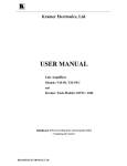
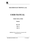
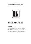
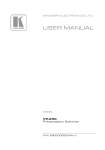
1
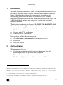
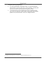
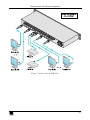
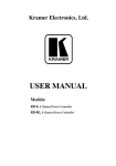
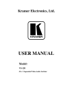
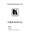
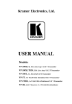
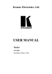
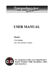
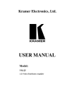
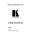
Kramer Electronics, Ltd.
Preliminary
USER MANUAL
Models:
VM-5ARII, Video Audio Distribution Amplifier
VM-20ARII, 1:20 Programmable Video Audio Distributor
VM-1411, 1:10 Video/Audio Distributor
Contents
Contents
1
2
2.1
3
3.1
3.2
3.3
4
4.1
4.2
4.3
5
6
6.1
6.2
6.3
7
Introduction
Getting Started
Quick Start
Overview
The VM-5ARII Video Audio Distribution Amplifier
The VM-20ARII 1:20 Programmable Video Audio Distributor
The VM-1411 1:10 Video/Audio Distributor
Your Distributors
Your VM-5ARII Video Audio Distribution Amplifier
Your VM-20ARII 1:20 Programmable Video Audio Distributor
Your VM-1411 1:10 Video/Audio Distributor
Installing the VM-20ARII in a Rack
Connecting the Distribution Amplifiers
Connecting the VM-5ARII Video Audio Distribution Amplifier
Connecting the VM-20ARII Video Audio Distributor
Connecting the VM-1411 1:10 Video/Audio Distributor
Technical Specifications
1
1
3
5
5
5
6
6
6
8
10
13
14
14
16
18
20
Figures
Figure 1: VM-5ARII Video Audio Distribution Amplifier
Figure 2: VM-20ARII 1:20 Programmable Video Audio Distributor
Figure 3: VM-20ARII Underside
Figure 4: VM-1411 1:10 Video/Audio Distributor
Figure 5: Connecting the VM-5ARII
Figure 6: Connecting the VM-20ARII
Figure 7: Connecting the VM-1411
7
9
10
11
15
17
19
Tables
Table 1: VM-5ARII Video Audio Distribution Amplifier
Table 2: VM-20ARII 1:20 Programmable Video Audio Distributor
Table 3: VM-20ARII Underside
Table 4: VM-1411 Functions
Table 5: VM-5ARII Technical Specifications
Table 6: VM-20ARII Technical Specifications
Table 7: VM-1411 Technical Specifications
8
10
10
12
20
21
21
i
Introduction
1
Introduction
Welcome to Kramer Electronics! Since 1981, Kramer Electronics has been
providing a world of unique, creative, and affordable solutions to the vast
range of problems that confront the video, audio, presentation, and
broadcasting professional on a daily basis. In recent years, we have
redesigned and upgraded most of our line, making the best even better! Our
1,000-plus different models now appear in 11 groups1 that are clearly
defined by function.
Thank you for purchasing the Kramer VM-5ARII, VM-20ARII, VM-1411
Video Distribution Amplifiers, which are ideal for:
Any professional A/V system requiring a compact, high-quality DA
Retail stores and other point-of-sale display systems
Security and CCTV applications
Studio RGB/YUV distribution
Each package includes the following items:
The VM-5ARII, VM-20ARII, or VM-1411 Distributor
Power cord2
This user manual3
2
Getting Started
We recommend that you:
Unpack the equipment carefully and save the original box and
packaging materials for possible future shipment
Review the contents of this user manual
Use Kramer high-performance high-resolution cables4
1 GROUP 1: Distribution Amplifiers; GROUP 2: Switchers and Matrix Switchers; GROUP 3: Control Systems;
GROUP 4: Format/Standards Converters; GROUP 5: Range Extenders and Repeaters; GROUP 6: Specialty AV Products;
GROUP 7: Scan Converters and Scalers; GROUP 8: Cables and Connectors; GROUP 9: Room Connectivity;
GROUP 10: Accessories and Rack Adapters; GROUP 11: Sierra Products
2 We recommend that you use only the power cord supplied with this device
3 Download up-to-date Kramer user manuals from our Web site at http://www.kramerelectronics.com
4 The complete list of Kramer cables is on our Web site at http://www.kramerelectronics.com
1
Getting Started
To achieve the best performance:
Use only good quality connection cables1 to avoid interference,
deterioration in signal quality due to poor matching, and elevated
noise levels (often associated with low quality cables).
Avoid interference from neighboring electrical appliances that
may adversely influence signal quality and position your Kramer
product away from moisture, excessive sunlight and dust
1 Available from Kramer Electronics on our Web site at http://www.kramerelectronics.com
2
KRAMER: SIMPLE CREATIVE TECHNOLOGY
Getting Started
2.1
Quick Start
This quick start chart summarizes the basic setup and operation steps.
3
Getting Started
4
KRAMER: SIMPLE CREATIVE TECHNOLOGY
Overview
3
Overview
This section gives an overview of the:
VM-5ARII Video Audio Distribution Amplifier, see section 3.1
VM-20ARII 1:20 Programmable Video Audio Distributor, see
section 3.2
VM-1411 1:10 Video/Audio Distributor, see section 3.3
3.1
The VM-5ARII Video Audio Distribution Amplifier
The Kramer VM-5ARII is a high-performance distribution amplifier for
composite or SDI video and unbalanced stereo audio signals. It takes one
input, provides correct buffering and isolation and distributes the signal to
five identical outputs.
More specifically, the VM-5ARII features:
High bandwidth 360MHz (-3dB)
1 composite video input and 5 outputs on BNC connectors
1 unbalanced stereo input and 5 outputs on RCA connectors
Looping input
Selectable input signal termination
Video level and equalization, and audio level controls
Video AC/DC coupling detection
Standard 19” 1U rack mount size
3.2
The VM-20ARII 1:20 Programmable Video Audio Distributor
The VM-20ARII is a multi-format, high-performance distribution amplifier
that can be configured for composite or SDI video and unbalanced stereo
audio signals. It can be configured as a 1:10 distribution amplifier for
s-Video (Y/C) signals or a 1:5 distribution amplifier for RGBS signals,
both with unbalanced stereo audio.
More specifically, the VM-20ARII features:
High bandwidth of 430MHz (-3dB)
1 video input and 20 outputs on BNC connectors
1 unbalanced stereo input and 20 outputs on RCA connectors
Looped input capability
Grouped audio level control
Selectable input signal termination
5
Your Distributors
Audio level and video level and equalization controls
Video AC/DC coupling selection
Standard 19” 2U rack mount size
3.3
The VM-1411 1:10 Video/Audio Distributor
The VM-1411 is a dual mode distribution amplifier for composite video and
balanced stereo audio signals. It can be configured as a 1:5 distribution
amplifier for s-Video (Y/C) signals with balanced stereo audio.
More specifically, the VM-1411 features:
Dual mode configuration as a 1:10 (composite) or 1:5 (s-Video) DA
Grouped audio level controls
Level (gain) and EQ (peaking) controls
Looping input
Selectable input signal termination
Video AC/DC coupling selection
Standard 19” 1U rack mount size
4
Your Distributors
This section defines your:
VM-5ARII Video Audio Distribution Amplifier, see section 4.1
VM-20ARII 1:20 Programmable Video Audio Distributor, see
section 4.2
VM-1411 1:10 Video/Audio Distributor, see section 4.3
4.1
Your VM-5ARII Video Audio Distribution Amplifier
Figure 1 and Table 1 define the VM-5ARII.
6
KRAMER: SIMPLE CREATIVE TECHNOLOGY
Figure 1: VM-5ARII Video Audio Distribution Amplifier
Your Distributors
7
Your Distributors
Table 1: VM-5ARII Video Audio Distribution Amplifier Features
#
1
2
3
4
5
6
7
8
9
10
11
12
13
14
4.2
Feature
Illuminated Power Switch
VIDEO IN BNC Connector
75 /Hi-Z Pushbutton
Function
Illuminated switch for turning the unit ON or OFF
Connects to the video source
Press in for input 75 termination, release for no
termination
DC/AC Pushbutton
Press in for DC coupling, release for AC coupling
VIDEO LOOP BNC Connector
Connects to a display
VIDEO GAIN Control
Adjusts the video gain level
VIDEO EQ. Control
Adjusts the cable compensation equalization level
VIDEO OUT BNC Connectors
Connects to the video acceptor (from 1 to 5)
AUDIO IN RCA Connectors (L and R)
Connects to the L and R channels of the audio source
AUDIO LOOP RCA Connectors (L and R)
Connects to an audio acceptor
AUDIO GAIN R
Controls the volume on the right audio channel
AUDIO GAIN L
Controls the volume on the left audio channel
AUDIO OUT RCA RCA Connectors (L and R) Connects to the audio acceptors (from 1 to 5)
Power Connector with Fuse
AC connector for supplying power to the unit
Your VM-20ARII 1:20 Programmable Video Audio Distributor
Figure 2, Figure 3, Table 2 and Table 3 define the VM-20ARII.
8
KRAMER: SIMPLE CREATIVE TECHNOLOGY
Figure 2: VM-20ARII 1:20 Programmable Video Audio Distributor
Your Distributors
9
Your Distributors
Table 2: VM-20ARII 1:20 Programmable Video Audio Distributor Features
#
Feature
Function
1
2
3
Illuminated Power Switch
STEREO/BAL pushbuttons
OUT 1-20 (L, R) audio GAIN trimmers
Illuminated switch for turning the unit ON or OFF
Select stereo or balanced mode of operation (pushed=balanced).
Controls audio level of outputs 1 to 20
4
OUT 1-20 EQ. and GAIN trimmers
1:20, 2x1:10, 4x1:5, 1:10+2x1:5 AUDIO
Operating Mode Switches
Control video level and cable equalization of outputs 1 to 20.
5
6
7
8
9
10
11
Programming switches for audio mode of operation as follows:
1:20 – Splits input “1” to all 20 outputs
2x1:10 – Splits input "1" to outputs "1-10" and input "3" to outputs "11-20".
4x1:5 – Splits four inputs to four consecutive sets of five outputs each.
1:10+2x1:5 – Splits input "1" to outputs "1-10", input "3" to outputs "11-15"
and input "4" to outputs "16-20"
1:20, 2x1:10, 4x1:5, 1:10+2x1:5 VIDEO Programming switches for video mode of operation as follows:
Operating Mode Switches
1:20 – Splits input “1” to all 20 outputs.
2x1:10 – Splits input "1" to outputs "1-10" and input "3" to outputs "11-20".
4x1:5 – Splits four inputs to four consecutive sets of five outputs each.
1:10+2x1:5 – Splits input "1" to outputs "1-10", input "3" to outputs "11-15"
and input "4" to outputs "16-20"
VIDEO INPUTS (1-4) and LOOP (1-4) Connect to the video sources and input loops
BNC Connectors
AUDIO IN (L and R) (1-4) RCA
Connect to the L and R channels of the audio source
Connectors
AUDIO OUT (L and R) (1-20) RCA
Connect to the audio acceptors (from 1 to 20)
Connectors
VIDEO OUTPUTS (1-20) BNC
Connect to the video acceptors (from 1 to 20)
Connectors
Power Connector with Fuse
AC connector for supplying power to the unit
#
12
13
Feature
TERM/75 Switches
(IN1-IN4)
AC/DC Switches
(IN1-IN4)
Function
Select 75 for termination (up) or
HI-Z for looping (down)
Select DC (up) or AC (down)
coupling
Table 3: VM-20ARII Underside Features
Figure 3: VM-20ARII
Underside
4.3
Your VM-1411 1:10 Video/Audio Distributor
Figure 4 and Table 4 define the VM-1411.
10
KRAMER: SIMPLE CREATIVE TECHNOLOGY
Figure 4: VM-1411 1:10 Video/Audio Distributor
Your Distributors
11
Your Distributors
Table 4: VM-1411 Features
#
1
2
3
4
Feature
Illuminated Power Switch
L AUDIO Trimmer (B)
R AUDIO Trimmer (B)
AUDIO MODE (2 x 1:5, 1:10)
Pushbutton
5
6
7
8
9
L AUDIO Trimmer (A)
R AUDIO Trimmer (A)
EQ Trimmer (B)
LEVEL Trimmer (B)
VIDEO MODE (2 x 1:5, 1:10)
Pushbutton
10
11
12
EQ Trimmer (A)
LEVEL Trimmer (A)
5 AUDIO outputs LA, RA Terminal
Block Connectors
L, R Terminal Block Connectors
L, R Terminal Block Connectors
5 AUDIO outputs LB, RB Terminal
Block Connectors
OUT 1–5 BNC Connectors
LOOP BNC Connector
Channel A 75 Pushbutton
Channel A DC Pushbutton
IN A BNC Connector
IN B BNC Connector
Channel B 75 Pushbutton
Channel B DC Pushbutton
LOOP BNC Connector
OUT 1–5 BNC Connectors
Power Connector with Fuse
13
14
15
16
17
18
19
20
21
22
23
24
25
26
12
Function
Illuminated switch for turning the unit ON or OFF
Controls audio level of left channel B
Controls audio level of right channel B
Selects either 1:10 or 2 x 1:5 audio operation:
1:10 position (pressed) – splits input "A" to all 10 outputs
2 x 1:5 position (released) – splits inputs "A" and "B" to outputs "A"
(1-5) and "B" (1-5) respectively.
Controls audio level of left channel A
Controls audio level of right channel A
Controls cable equalization of channel B video outputs
Controls video level of channel B video outputs
Selects either 1:10 or 2 x 1:5 video operation:
1:10 position (pressed)- splits input "A" to all 10 outputs
2 x 1:5 position (released)- splits inputs "A" and "B" to outputs "A"
(1-5) and "B" (1-5) respectively
Controls cable equalization of channel A video outputs
Controls video level of channel A video outputs
Connect to audio acceptors A (1 to 5): LA to the left, RA to the
right
Connects to audio input source A
Connects to audio input source B
Connect to audio acceptors B (1 to 5): LB to the left, RB to the
right
Connect to channel A video acceptors (1 to 5)
Connect to video acceptor or display
Press for 75 termination on channel A, release for looping Hi-z
Press for DC coupling, release for AC coupling
Connects to video input source A
Connects to video input source B
Press for 75 termination on channel B, release for looping Hi-z
Press for DC coupling, release for AC coupling
Connect to video acceptor or display
Connect to channel B video acceptors (1 to 5)
AC connector for supplying power to the unit
Installing the VM-20ARII in a Rack
5
Installing the VM-20ARII in a Rack
This section describes how to install the VM-20ARII in a rack.
Before Installing in a rack
Before installing in a rack, be sure that the environment is
within the recommended range:
Operating temperature range +5º to +45º C (41º to 113º F)
Operating humidity range
10 to 90% RHL, non-condensing
Storage temperature range
-20º to +70º C (-4º to 158º F)
Storage humidity range
5 to 95% RHL, non-condensing
How to Rack Mount
To rack-mount a machine:
1. Attach both ear brackets to the
machine. To do so, remove the
screws from each side of the
machine (5 on each side), and
replace those screws through the
ear brackets.
CAUTION!!
When installing on a 19" rack, avoid hazards by taking
care that:
1. It is located within the recommended environmental
conditions, as the operating ambient temperature of a
closed or multi unit rack assembly may exceed the
room ambient temperature.
2. Once rack mounted, enough air will still flow around
the machine.
3. The machine is placed straight in the correct
horizontal position.
4. You do not overload the circuit(s). When connecting
the machine to the supply circuit, overloading the
circuits might have a detrimental effect on overcurrent
protection and supply wiring. Refer to the appropriate
nameplate ratings for information. For example, for
fuse replacement, see the value printed on the
product label.
5. The machine is earthed (grounded) in a reliable way
and is connected only to an electricity socket with
grounding. Pay particular attention to situations where
electricity is supplied indirectly (when the power cord
is not plugged directly into the socket in the wall), for
example, when using an extension cable or a power
strip, and that you use only the power cord that is
supplied with the machine.
2. Place the ears of the machine
against the rack rails, and insert the
proper screws (not provided)
through each of the four holes in the
rack ears.
Note that:
In some models, the front panel
may feature built-in rack ears
Detachable rack ears can be
removed for desktop use
Always mount the machine in the
rack before you attach any cables
or connect the machine to the
power
If you are using a Kramer rack
adapter kit (for a machine that is not
19"), see the Rack Adapters user
manual for installation instructions
(you can download it at:
http://www.kramerelectronics.com)
13
Connecting the Distribution Amplifiers
6
Connecting the Distribution Amplifiers
This section describes how to connect the:
VM-5ARII Video Audio Distribution Amplifier, see section 6.1
VM-20ARII 1:20 Programmable Video Audio Distributor, see
section 6.2
VM-1411 1:10 Video/Audio Distributor, see section 6.3
6.1
Connecting the VM-5ARII Video Audio Distribution Amplifier
To connect the VM-5ARII, as shown in the example in Figure 5, do the
following1:
1. Connect the input video source (for example, a composite video player) to
the VIDEO INPUT BNC connector.
2. Connect the input audio source (for example, the audio from a composite
video player) to the AUDIO IN RCA connectors noting the right and left
channels.
3. Connect the VIDEO OUT 1 to 5 BNC connectors to up to 5 acceptors2 (for
example, composite video recorders).
4. Connect the AUDIO OUT 1 to 5 RCA connectors to up to 5 acceptors2 (for
example, the audio input on the composite video recorders).
5. If needed, connect the VIDEO LOOP BNC connector to an acceptor (for
example, a composite video display or another VM-5ARII) and set the
termination pushbutton to 75 .
6. Connect the power cord3 to the unit (not shown in the illustration) and then
to the mains electricity. Switch on the power.
7. If needed, adjust the VIDEO GAIN or EQ controls or the AUDIO GAIN on
the front panel.
1 Switch OFF the power on each device before connecting it to your VM-5ARII. After connecting, switch on the VM-5ARII
power and then switch on the power on each device
2 You are not required to connect two acceptors
3 Use the power cord supplied with the unit
14
Connecting the Distribution Amplifiers
Figure 5: Connecting the VM-5ARII
15
Connecting the Distribution Amplifiers
6.2
Connecting the VM-20ARII Video Audio Distributor
To connect the VM-20ARII, as shown in the example in Figure 6, do the
following1:
1. Connect up to 4 input video sources (for example, composite video players)
to the VIDEO INPUTS 1 to 4 BNC connectors.
2. Connect up to 4 input audio sources (for example, the audio from the video
players) to the AUDIO INPUTS RCA connectors 1 to 4 noting the right and
left channels.
3. Connect the VIDEO OUT 1 to 20 BNC connectors to up to 20 acceptors2
(for example, composite video recorders).
4. Connect the AUDIO OUT 1 and 20 RCA connectors to up to 20 acceptors2
(for example, the audio input on the video recorders).
5. If needed, connect the VIDEO LOOP BNC connector to an acceptor (for
example, a composite video display or another VM-20ARII) and set the
termination pushbutton to 75 .
6. Connect the power cord3 to the unit (not shown in the illustration) and then
to the mains electricity. Switch on the power.
7. If needed, adjust the VIDEO GAIN or EQ controls or the AUDIO GAIN on
the front panel.
8. Set the mode of operation by pressing one of the operating mode control
switches (one set for audio and one set for video) as follows:
Press the 1:20 switch to split input “1” to all 20 outputs
Press the 2x1:10 switch to split input "1" to outputs "1-10"
and input "3" to outputs "11-20"
Press the 4x1:5 switch to split four inputs to four consecutive
sets of five outputs each
Press the 1:10+2x1:5 switch to split input "1" to outputs "110", input "3" to outputs "11-15" and input "4" to outputs
"16-20"
1 Switch OFF the power on each device before connecting it to your VM-20ARII. After connecting, switch on the
VM-20ARII power and then switch on the power on each device
2 You are not required to connect all the acceptors
3 Use the power cord supplied with the unit
16
Connecting the Distribution Amplifiers
Figure 6: Connecting the VM-20ARII
17
Connecting the Distribution Amplifiers
6.3
Connecting the VM-1411 1:10 Video/Audio Distributor
To connect the VM-1411, as shown in the example in Figure 7, do the
following1:
1. Connect up to 2 input video sources (for example, composite video players)
to the VIDEO IN A and VIDEO IN B BNC connectors.
2. Connect up to 2 input audio sources (for example, the audio from the
composite video players) to the L and R terminal block connectors
associated with IN A and IN B.
3. Connect the VIDEO OUT 1 to 5 BNC connectors to up to 5 acceptors2 (for
example, composite video recorders) on channels A and B.
4. Connect the AUDIO OUT 1 to 5 L and R terminal block connectors to up
to 5 acceptors2 (for example, the audio input on the video recorders) on
channels A and B.
5. If needed, connect the VIDEO LOOP BNC connector for each channel to
an acceptor (for example, a composite video display or another VM-1411)
and set the termination pushbutton to 75 for each connected channel. Set
AC or DC coupling as needed.
6. Connect the power cord3 to the unit (not shown in the illustration) and then
to the mains electricity. Switch on the power.
7. If needed, adjust the VIDEO GAIN or EQ controls or the AUDIO GAIN on
the front panel.
8. Set the mode of operation by pressing one of the operating mode control
switches as follows:
Press the 2x1:5/1:10 switch to split input "A" to all 10 outputs
Release the 2x1:5/1:10 switch to split inputs "A" and "B" to
outputs sets "A" and "B" respectively.
1 Switch OFF the power on each device before connecting it to your VM-1411. After connecting, switch on the VM-1411
power and then switch on the power on each device
2 You are not required to connect all the acceptors
3 Use the power cord supplied with the unit
18
Connecting the Distribution Amplifiers
Figure 7: Connecting the VM-1411
19
Technical Specifications
7
Technical Specifications
The technical specifications1 of the distribution amplifiers are shown in
Table 5, Table 6, and Table 7:
Table 5: VM-5ARII Technical Specifications
INPUT:
1 video, composite or single component, looping, 1Vpp/75 on BNC
connectors with termination switch;
1 audio stereo looping, +4dBu/50k on RCA connectors
OUTPUT:
5 video, composite or single component, 1 Vpp/75 on BNC connectors; 5
audio stereo, +4dBu/150 , on RCA connectors
MAX. OUTPUT:
Video: 2.2Vpp; Audio: 27Vpp
VIDEO BANDWIDTH (-3dB):
360MHz
AUDIO BANDWIDTH (-3dB):
60kHz
DIFF. GAIN:
0.03%
DIFF. PHASE:
0.06Deg
K-FACTOR:
0.05%
VIDEO S/N RATIO:
76dB
AUDIO S/N RATIO:
85dB
AUDIO THD:
0.021% (1V, 1kHz.)
CONTROL:
Video gain: -1 to +1.8dB; audio gain: -40 to +6dB; EQ.: 0 to +2.5dB, audio: 0.2
to +6dB.
COUPLING:
DC/AC selectable (video), AC (audio.)
POWER SOURCE:
230V AC, 50/60Hz, (115V U.S.A.) 21VA.
DIMENSIONS:
19” x 7” x 1U W, D, H, rack mountable.
WEIGHT:
1.94kg (4.3lbs) approx.
ACCESORIES:
Power cord.
1 Specifications are subject to change without notice
20
Technical Specifications
Table 6: VM-20ARII Technical Specifications
INPUT:
4 video looping, 1Vpp/75 on BNC connectors with termination switches; 4
audio stereo (or balanced mono) +4dBu/50k , on RCA connectors
OUTPUT:
Video: 20 (1:20, 2x1:10, 4x1:5, 1:10, 2x1:5) 1Vpp/75 on BNC connectors;
Audio: 20 (1:20, 2x1:10, 4x1:5, 1:10, 2x1:5) stereo or balanced mono,
+4dBu/50 , on RCA connectors
VIDEO BANDWIDTH (-3dB):
430MHz
AUDIO BANDWIDTH (-3dB):
110kHz
DIFF. GAIN:
0.06%
DIFF. PHASE:
0.08Deg
VIDEO S/N RATIO:
76dB
AUDIO S/N RATIO:
80dB
VIDEO CONTROL:
-1.2/+1.7dB level, 0/+2.4dB EQ
AUDIO CONTROL:
+0.3/+6.2dB
VIDEO COUPLING:
DC/AC user selectable
AUDIO COUPLING:
AC (input), DC (output)
AUDIO THD+NOISE:
0.02%
2nd HARMONIC:
0.002%
POWER SOURCE:
Universal switching power supply: 100-240 VAC, 50/60Hz 18.5VA
DIMENSIONS:
19” x 7” x 2U W, D, H, rack mountable
WEIGHT:
3.6kg (8lbs) approx
ACCESORIES:
Power cord
Table 7: VM-1411 Technical Specifications
INPUT:
2 composite/single component video, looping, 1Vpp/75 on BNC connectors
with termination switch; 2 balanced audio stereo up to +4dBu/50k on
detachable terminal blocks
OUTPUT:
2x5 composite/single component video, 1Vpp/75 on BNCs; 2x5 balanced
audio stereo 4dBu/50 , on detachable terminal blocks
MAX. OUTPUT:
Video: 1.8Vpp; Audio: +24dBu
VIDEO BANDWIDTH (-3dB):
240MHz
AUDIO BANDWIDTH (-3dB):
60kHz
DIFF. GAIN:
0.2%
DIFF. PHASE:
0.2Deg
K-FACTOR:
0.05%
VIDEO S/N RATIO:
77dB
AUDIO S/N RATIO:
Better than 87dB @1Vpp
CONTROL:
Front accessible trimmers for video gain and EQ. and for audio L and R levels
COUPLING:
DC or AC (video); AC (audio)
AUDIO THD:
0.02%
POWER SOURCE:
230V AC 50/60Hz (115V U.S.A.) 19.5VA
DIMENSIONS:
19” x 7” x 1U W, D, H, rack mountable
WEIGHT:
2.9kg (6.4lbs) approx
ACCESORIES:
Power cord
OPTIONS :
Kramer 3.5mm to IR Emitter Control Cable (C-A35/IRE-10); Kramer 3.5mm to
Dual IR Emitter Control Cable (C-A35/2IRE- 10); 15 meter and 20 meter IR
emitter extension cables
21
22
For the latest information on our products and a list of Kramer
distributors, visit our Web site: www.kramerelectronics.com
where updates to this user manual may be found.
We welcome your questions, comments and feedback.
Safety Warning:
Disconnect the unit from the power supply before
opening/servicing.
Caution
Kramer Electronics, Ltd.
Web site: www.kramerelectronics.com
E-mail: [email protected]
P/N: 2900-001005 REV 2