1
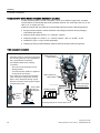
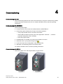
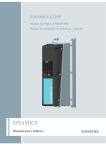
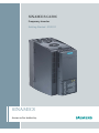
SINAMICS G120C
Frequency inverter
Getting Started · 01/2011
SINAMICS
Answers for industry.
Frequency inverter
1
___________________
Safety notes
2
___________________
Introduction
SINAMICS
SINAMICS G120C
Frequency inverter
3
___________________
Installing
4
___________________
Commissioning
5
___________________
Parameter list
6
___________________
Trouble shooting
Getting Started
Edition 01/2011, Firmware V4.4
01/2011, FW 4.4
A5E02999802A AB
Legal information
Legal information
Warning notice system
This manual contains notices you have to observe in order to ensure your personal safety, as well as to prevent
damage to property. The notices referring to your personal safety are highlighted in the manual by a safety alert
symbol, notices referring only to property damage have no safety alert symbol. These notices shown below are
graded according to the degree of danger.
DANGER
indicates that death or severe personal injury will result if proper precautions are not taken.
WARNING
indicates that death or severe personal injury may result if proper precautions are not taken.
CAUTION
with a safety alert symbol, indicates that minor personal injury can result if proper precautions are not taken.
CAUTION
without a safety alert symbol, indicates that property damage can result if proper precautions are not taken.
NOTICE
indicates that an unintended result or situation can occur if the corresponding information is not taken into
account.
If more than one degree of danger is present, the warning notice representing the highest degree of danger will
be used. A notice warning of injury to persons with a safety alert symbol may also include a warning relating to
property damage.
Qualified Personnel
The product/system described in this documentation may be operated only by personnel qualified for the specific
task in accordance with the relevant documentation for the specific task, in particular its warning notices and
safety instructions. Qualified personnel are those who, based on their training and experience, are capable of
identifying risks and avoiding potential hazards when working with these products/systems.
Proper use of Siemens products
Note the following:
WARNING
Siemens products may only be used for the applications described in the catalog and in the relevant technical
documentation. If products and components from other manufacturers are used, these must be recommended
or approved by Siemens. Proper transport, storage, installation, assembly, commissioning, operation and
maintenance are required to ensure that the products operate safely and without any problems. The permissible
ambient conditions must be adhered to. The information in the relevant documentation must be observed.
Trademarks
All names identified by ® are registered trademarks of the Siemens AG. The remaining trademarks in this
publication may be trademarks whose use by third parties for their own purposes could violate the rights of the
owner.
Disclaimer of Liability
We have reviewed the contents of this publication to ensure consistency with the hardware and software
described. Since variance cannot be precluded entirely, we cannot guarantee full consistency. However, the
information in this publication is reviewed regularly and any necessary corrections are included in subsequent
editions.
Siemens AG
Industry Sector
Postfach 48 48
90026 NÜRNBERG
GERMANY
A5E02999802A AB
Ⓟ 01/2011
Copyright © Siemens AG 2011.
Technical data subject to change
Table of contents
1
Safety notes............................................................................................................................................... 5
2
Introduction................................................................................................................................................ 7
3
4
2.1
SINAMICS G120C inverter ............................................................................................................7
2.2
Commissioning tools......................................................................................................................8
Installing .................................................................................................................................................... 9
3.1
Dimensions ....................................................................................................................................9
3.2
Power connections.......................................................................................................................11
3.3
Process and user interfaces ........................................................................................................13
3.4
Terminal strips on the inverter .....................................................................................................14
3.5
Pre-defined I/O-configuration.......................................................................................................15
Commissioning ........................................................................................................................................ 19
4.1
BOP-2 menu structure .................................................................................................................20
4.2
Basic commissioning ...................................................................................................................21
4.3
Freely selecting and changing parameters..................................................................................22
4.4
Changing the function of terminals ..............................................................................................23
4.5
Releasing "Safe Torque Off"........................................................................................................24
4.6
Getting the GSD file .....................................................................................................................24
5
Parameter list .......................................................................................................................................... 25
6
Trouble shooting ...................................................................................................................................... 39
6.1
List of alarms and faults ...............................................................................................................39
6.2
Further information.......................................................................................................................44
Frequency inverter
Getting Started, 01/2011, FW 4.4, A5E02999802A AB
3
Table of contents
Frequency inverter
4
Getting Started, 01/2011, FW 4.4, A5E02999802A AB
1
Safety notes
It has to be ensured by the machine manufacturer, that the line-side overcurrent protection
equipment interrupts within 5 s (immovable equipment and modules in immovable
equipment) in the case of minimum fault current (current on complete insulation failure to
accessible conductive parts that are not live during operation and maximum current loop
resistance).
DANGER
Electrical shock
Hazardous voltage is still present for up to 5 minutes after the power supply has been
switched off.
It is not permissible to carry out any installation work before this time has expired!
WARNING
This equipment contains dangerous voltages and controls potentially dangerous rotating
mechanical parts.
Protection in case of direct contact by means of SELV / PELV is only permissible in areas
with equipotential bonding and in dry indoor rooms. If these conditions are not fulfilled,
other protective measures against electric shock must be applied e.g. protective insulation.
The inverter must always be grounded. As the earth leakage for this product can be greater
than 3.5 mA a.c., a fixed earth connection is required and the minimum size of the
protective earth conductor shall comply with the local safety regulations for high leakage
current equipment.
Install the inverter on a metal mounting plate. The mounting plate has to be unpainted and
with a good electrical conductivity.
It is strictly prohibited for any mains disconnection to be performed on the motor-side of the
system, if the inverter is in operation and the output current is not zero.
Take particular notice of the general and regional installation and safety regulations
regarding work on dangerous voltage installations (e.g. EN 50178) as well as the relevant
regulations regarding the correct use of tools and personal protective equipment (PPE).
CAUTION
ESD protection
Transport and
storage
Static discharges on surfaces or interfaces that are not generally accessible (e.g. terminal
or connector pins) can cause malfunctions or defects. Therefore, when working with
inverters or inverter components, ESD protective measures should be observed.
CAUTION
The level of physical shocks and vibration during transport and storage must correspond to
class 2M3 according to EN 60721-3-2. It is important that the equipment is protected from
water (rainfall) and excessive temperatures.
Frequency inverter
Getting Started, 01/2011, FW 4.4, A5E02999802A AB
5
Safety notes
Installation and
Commissioning
Operation
WARNING
Wherever faults occurring in the control equipment can lead to substantial material damage
or even grievous bodily injury (that is, potentially dangerous faults), additional external
precautions must be taken or facilities provided to ensure or enforce safe operation, even
when a fault occurs (e.g. independent limit switches, mechanical interlocks, etc.).
WARNING
Emergency Stop facilities according to EN 60204, IEC 204 (VDE 0113) must remain
operative in all operating modes of the control equipment. Any disengagement of the
Emergency Stop facility must not lead to an uncontrolled or an undefined restart of the
equipment.
WARNING
Filtered drives can only be used on power systems with grounded starpoint.
CAUTION
This equipment is suitable for use in a power system up to 10,000 symmetrical amperes
(rms), for the maximum rated voltage + 10 % when protected by an appropriate standard
fuse (refer to the catalogue for the type of fuse).
WARNING
Risk of fire
If an unsuitable braking resistor is used, this could result in a fire and severely damage,
people, property and equipment. It is essential that not only the correct braking resistor is
used, but it is installed correctly according to the instructions delivered with the braking
resistor.
The temperature of braking resistors increases significantly during operation. For this
reason, avoid coming into direct contact with braking resistors. Maintain sufficient
clearances around the braking resistor and ensure that there is adequate ventilation.
Repair
WARNING
Repairs on equipment may only be carried out by Siemens Service, by repair centers
authorized by Siemens or by authorized personnel who are thoroughly acquainted with all
the warnings and operating procedures contained in this manual.
Any defective parts or components must be replaced using parts contained in the relevant
spare parts list.
Frequency inverter
6
Getting Started, 01/2011, FW 4.4, A5E02999802A AB
2
Introduction
This Getting Started Guide describes how you do the installing and basic commissioning of
the SINAMICS G120C inverter.
2.1
SINAMICS G120C inverter
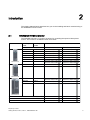
The SINAMICS G120C is a range of inverters for controlling the speed of three phase
motors. The inverter is available in three frame sizes.
)UDPH6L]H$
5DWHGRXWSXW 5DWHGRXWSXW
SRZHU
FXUUHQW
EDVHGRQ/RZ2YHUORDG
2UGHUQXPEHU
N:
N:
N:
N:
N:
N:
N:
$
$
$
$
$
$
$
6/.(8
6/.(8
6/.(8
6/.(8
6/.(8
6/.(8
6/.(8
6/.($
6/.($
6/.($
6/.($
6/.($
6/.($
6/.($
N:
N:
$
$
6/.(8
6/.(8
6/.($
6/.($
N:
N:
N:
$
$
$
6/.(8
6/.(8
6/.(8
6/.($
6/.($
6/.($
8QILOWHUHG
)LOWHUHG
)UDPH6L]H%
)UDPH6L]H&
8660RGEXV578
352),%86'3
&$1RSHQ
%
3
&
%
3
&
Frequency inverter
Getting Started, 01/2011, FW 4.4, A5E02999802A AB
7
Introduction
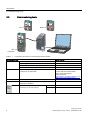
2.2 Commissioning tools
2.2
Commissioning tools
,23
%23
,23
+DQGKHOG
Table 2- 1
Components and tools for commissioning and data backup
Component or tool
Operator Panels
Order number
BOP-2 - snapped on the inverter.
6SL3255-0AA00-4CA1
IOP - snapped on the inverter or used with the handheld.
6SL3255-0AA00-4JA0
IOP Handheld.
6SL3255-0AA00-4HA0
IOP/BOP-2 Mounting Kit IP54/UL Type 12.
6SL3256-0AP00-0JA0
STARTER
Commissioning tool (PC software) - connected to the
inverter using an USB cable.
You obtain STARTER on a DVD (Order
number: 6SL3072-0AA00-0AG0)
and it can be downloaded:
Starter download
(http://support.automation.siemens.com/
WW/view/en/10804985/133100)
PC Connection Kit
Comprising STARTER DVD and USB cable.
6SL3255-0AA00-2CA0
Drive ES Basic
For commissioning the inverter via PROFIBUS interface.
Implements STARTER.
6SW1700-5JA00-4AA0
Optional memory card for storing and
transferring the inverter settings
MMC card
6SL3254-0AM00-0AA0
SD card
6ES7954-8LB00-0AA0
Frequency inverter
8
Getting Started, 01/2011, FW 4.4, A5E02999802A AB
3
Installing
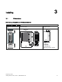
3.1
Dimensions
Dimensions, drill patterns and minimum distances
Frame Size A, 0.55 kW … 4.0 kW
Drill pattern [mm]
:LWK,23
Dimensions [mm]
$LU
Distances to other equipment
[mm]
)L[LQJV
[0EROWV
[0QXWV
[0ZDVKHUV
7LJKWHQLQJWRUTXH1P
Frequency inverter
Getting Started, 01/2011, FW 4.4, A5E02999802A AB
9
Installing
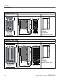
3.1 Dimensions
Frame Size B, 5.5 kW … 7.5 kW
)L[LQJV
[0EROWV
[0QXWV
[0ZDVKHUV
7LJKWHQLQJWRUTXH1P
Drill pattern [mm]
:LWK,23
$LU
Dimensions [mm]
Distances to other equipment
[mm]
Frame Size C, 11 kW … 18.5 kW
Drill pattern [mm]
:LWK,23
Dimensions [mm]
$LU
Distances to other equipment
[mm]
)L[LQJV
[0EROWV
[0QXWV
[0ZDVKHUV
7LJKWHQLQJWRUTXH1P
Frequency inverter
10
Getting Started, 01/2011, FW 4.4, A5E02999802A AB
Installing
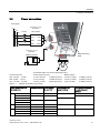
3.2 Power connections
3.2
Power connections
/LQHVXSSO\
/
/
/
3(
'HSHQGLQJRQ\RXU
DSSOLFDWLRQ
)XVHV
/LQHUHDFWRU
8
8
9
9
:
:
3(
3(
/
/
/
3(
5
5
'HSHQGLQJRQ\RXU
DSSOLFDWLRQ
0HWDOPRXQWLQJ
SODWH
%UDNLQJUHVLVWRU
8 9 :
8 9
:
3(
0
Permissible cable cross section (tightening torque)
Inverter frame size
Mains supply and motor
Braking resistor
FSA, 0.55 kW … 4.0 kW
2.5 mm² (0.5 Nm)
14 AWG (4.4 lbf in)
2.5 mm² (0.5 Nm)
14 AWG (4.4 lbf in)
FSB, 5.5 kW … 7.5 kW
6 mm² (0.6 Nm)
10 AWG (5.3 lbf in)
2.5 mm² (0.5 Nm)
14 AWG (4.4 lbf in)
FSC, 11.0 kW … 18.5 kW
16 mm² (1.5 Nm)
5 AWG (13.3 lfb in)
6 mm² (0.6 Nm)
10 AWG (5.3 lbf in)
Table 3- 1
External components of the inverter
Inverter Frame Size (FS)
and rated power
Standard fuse type Fuse type acc.
UL and cUL
Braking resistor for
dynamic braking
Line reactor for reducing
line-side harmonic
currents
FSA
0.55 kW … 1.1 kW
3NA3801 (6 A)
10 A class J
6SL3201-0BE14-3AA0
6SL3203-0CE13-2AA0
1.5 kW
3NA3803 (10 A)
10 A class J
3.0 kW
6SL3203-0CE21-0AA0
6SL3201-0BE21-0AA0
2.2 kW
3NA3805 (16 A)
15 A class J
5.5 kW
3NA3807 (20 A)
20 A class J
7.5 kW
3NA3810 (25 A)
25 A class J
11.0 kW
3NA3817 (40 A)
40 A class J
15.0 kW
3NA3820 (50 A)
50 A class J
18.5 kW
3NA3822 (63 A)
60 A class J
4.0 kW
FSB
FSC
6SL3201-0BE21-8AA0
6SL3203-0CE21-8AA0
6SL3201-0BE23-8AA0
6SL3203-0CE23-8AA0
Frequency inverter
Getting Started, 01/2011, FW 4.4, A5E02999802A AB
11
Installing
3.2 Power connections
Components for United States / Canadian installations (UL/cUL)
In order that the system is UL/cUL-compliant, use UL/cUL-certified J-type fuses, overload
circuit-breakers or intrinsically safe motor protection devices. For each frame size A to C use
class 1 75° C copper wire only.
Install the inverter with any external recommended suppressor with the following features:
● Surge-protective devices; device shall be a Listed Surge-protective device (Category
code VZCA and VZCA7)
● Rated nominal voltage 480/277 VAC, 50/60 Hz, 3-phase
● Clamping voltage VPR = 2000 V, IN = 3 kA min, MCOV = 550 VAC, SCCR = 40 kA
● Suitable for Type 1 or Type 2 SPD application
● Clamping shall be provided between phases and also between phase and ground
EMC compliant installation
Rules for EMC-compliant installation:
Install the inverter on a metal mounting plate.
The mounting plate has to be unpainted and
with a good electrical conductivity.
/
/
/
3(
Use shielded cables for the following
connections:
–
(0&FODPSIRU
FDEOHVKLHOG
Motor and motor temperature sensor
–
Braking resistor
–
Process interfaces (Field bus, digital and
analog inputs and outputs)
Use a clamp for connecting each shielded
cable. Connect the shield to the mounting
plate or to the shield plate through a good
electrical connection and through the largest
possible surface area.
5
5
8
9
:
(0&FODPSVIRU
FDEOHVKLHOG
&DEOHFRQQHFWHG
WRWHUPLQDOVWULS
/LQHVXSSO\
3UHVVFDEOH
VFUHHQRQ
VKLHOGSODWH
8QFRYHU
FDEOH
VFUHHQ
$
%UDNLQJUHVLVWRU
8 9
3(
:
0
$
Screening example for inverter frame size A
Frequency inverter
12
Getting Started, 01/2011, FW 4.4, A5E02999802A AB
Installing
3.3 Process and user interfaces
3.3
Process and user interfaces
0HPRU\FDUGVORW00&RU6'FDUGV
,QWHUIDFHIRURSHUDWRUSDQHO%23RU,23
86%LQWHUIDFHIRU67$57(5
6WDWXV/('V
5'<
%)
6$)(
',3VZLWFKHVIRUEXVDGGUHVV
%LW
%LW
%LW
%LW
%LW
%LW
%LW
21
2))
([DPSOH
$GGUHVV 21 2))
$QDORJLQSXW
',3VZLWFK
&XUUHQW 9ROWDJH
'HSHQGLQJRQILHOGEXV
*&8660%DQG*&&$1
%XVWHUPLQD
2)) 21
WLRQ
*&'3QRIXQFWLRQ
7HUPLQDOVWULSV
7HUPLQDOGHVLJQDWLRQV
)LHOGEXVLQWHUIDFH
QF
QF
9RXW
*1'
$,
$,
$2
*1'
'2
'2
7PRWRU
7PRWRU
*1'
',&20
',&20
',
',
',
',
',
',
'212
'2&20
'21&
9RXW
&$1RSHQ
866RU
0RGEXV578
352),%86
1RWXVHG
&$1B/&$1VLJQDOGRPLQDQWORZ
&$1B*1'&$1UHIHUHQFH
1RWXVHG
&$1B6+/'RSWLRQDOFDEOHVKLHOG
*1'RSWLRQDO&$1UHIHUHQFH
&$1B+&$1VLJQDOGRPLQDQWKLJK
1RWXVHG
1RWXVHG
9UHIHUHQFHSRWHQWLDO
5635HFHLYHDQGVHQG
5615HFHLYHDQGVHQG
&DEOHVKLHOG
1RWXVHG
6KLHOGJURXQGFRQQHFWLRQ
1RWXVHG
5['7['3UHFHLYHVHQGGDWD3%%
&1753FRQWUROVLJQDO
'*1'GDWDUHIHUHQFHSRWHQWLDO&&
93VXSSO\YROWDJHSRVLWLYH
1RWXVHG
5['7['1UHFHLYHVHQGGDWD1$$
1RWXVHG
Frequency inverter
Getting Started, 01/2011, FW 4.4, A5E02999802A AB
13
Installing
3.4 Terminal strips on the inverter
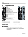
3.4
!N˖
Terminal strips on the inverter
7HUPLQDOV
([SODQDWLRQV
QF
1RWFRQQHFWHG
1RWFRQQHFWHG
9RXWSXWUHIHUUHGWR*1'PD[P$
2YHUDOOUHIHUHQFHSRWHQWLDO
$QDORJLQSXW99P$P$P$P$
5HIHUHQFHSRWHQWLDOIRUDQDORJLQSXW
QF
9RXW
*1'
$,
$,
9
!N˖
*1'
'2
'2
702725
702725
*1'
',&20
',&20
',
',
',
',
',
',
'212
'2&20
'21&
9RXW
9
$2
9
9
$QDORJRXWSXW99P$P$
2YHUDOOUHIHUHQFHSRWHQWLDO
'LJLWDORXWSXWSRVLWLYH$9'&
'LJLWDORXWSXWQHJDWLYH$9'&
0RWRUWHPSHUDWXUHVHQVRU37&.7<RUELPHWDO1&FRQWDFW
0RWRUWHPSHUDWXUHVHQVRU37&.7<RUELPHWDO1&FRQWDFW
2YHUDOOUHIHUHQFHSRWHQWLDO
5HIHUHQFHSRWHQWLDOIRUGLJLWDOLQSXWVDQG
5HIHUHQFHSRWHQWLDOIRUGLJLWDOLQSXWVDQG
'LJLWDOLQSXW
'LJLWDOLQSXW
'LJLWDOLQSXW
'LJLWDOLQSXW
'LJLWDOLQSXW
'LJLWDOLQSXW
'LJLWDORXWSXW1RUPDOO\2SHQFRQWDFW$9'&
'LJLWDORXWSXW&RPPRQFRQWDFW
'LJLWDORXWSXW1RUPDOO\&ORVHGFRQWDFW
9RXWSXWUHIHUHQFHSRWHQWLDO*1'PD[P$
9
9
9
9
Wiring variants
①
②
③
④
Wiring using the internal power supply
Digital input = HIGH if switch closed
Wiring using an external power supply
Digital input = HIGH if switch closed
Wiring using the internal power supply
Digital input = LOW if switch closed
Wiring using an external power supply
Digital input = LOW if switch closed
Permissible cable cross-section:
0.5 mm² (21 AWG) … 1.5 mm² (16 AWG)
Recommended cable cross section:
1 mm² (18 AWG)
EMC-compliant installation
● Use shielded cables for connecting the terminal strip to other components.
● Use a clamp for connecting the shielded cable. Connect the shield to the mounting plate
or to the shield plate through a good electrical connection and through the largest
possible surface area. The handling of shielded cables is shown in section Power
connections (Page 11).
Frequency inverter
14
Getting Started, 01/2011, FW 4.4, A5E02999802A AB
Installing
3.5 Pre-defined I/O-configuration
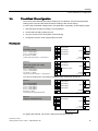
3.5
Pre-defined I/O-configuration
The inverter offers different pre-defined settings for its interfaces. Choose the appropriate
setting (macro) and wire the terminal strips according to the chosen setting.
If none of the pre-defined settings suites your application completely, do the following steps:
1. Wire the terminal strips according to your application.
2. Choose the best fitting setting (macro).
3. Set your chosen macro during basic commissioning.
4. Change the function of the inappropriate terminals.
Fixed speeds
0DFUR
7ZRIL[HGVSHHGV
S )L[HGVSHHG
S )L[HGVSHHG
',DQG', +,*+
,QYHUWHUDGGVIL[HGVSHHGIL[HGVSHHG
0DFUR
7ZRIL[HGVSHHGVZLWKVDIHW\
IXQFWLRQ672
S )L[HGVSHHG
S )L[HGVSHHG
',DQG', +,*+
0RWRUUXQVZLWKIL[HGVSHHGIL[HGVSHHG
',
',
',
',
',
',
$,
',
',
',
',
',
',
212))ULJKW
212))OHIW
$FNQRZOHGJH
)L[HGVSHHG
)L[HGVSHHG
)DXOW '2
$ODUP '2
6SHHG $2
99 212)))L[HGVSHHG
)L[HGVSHHG
$FNQRZOHGJH
5HVHUYHGIRU672
)DXOW '2
$ODUP '2
6SHHG $2
99 $, You have to release STO, see section: Releasing "Safe Torque Off" (Page 24).
0DFUR
)RXUIL[HGVSHHGV
S )L[HGVSHHG
S )L[HGVSHHG
S )L[HGVSHHG
S )L[HGVSHHG
6HYHUDO', +,*+
,QYHUWHUDGGVDFFRUGLQJIL[HGVSHHGV
0DFUR
)LHOGEXV352),%86'3
',
',
',
',
',
',
212)))L[HGVSHHG
)L[HGVSHHG
$FNQRZOHGJH
)L[HGVSHHG
)L[HGVSHHG
6SHHG $2
99 $, ',
',
',
',
',
',
$,
)DXOW '2
$ODUP '2
$FNQRZOHGJH
)DXOW '2
$ODUP '2
6SHHG $2
99 352),%86'3
7HOHJUDP
For getting the GSD file, see section: Getting the GSD file (Page 24).
Frequency inverter
Getting Started, 01/2011, FW 4.4, A5E02999802A AB
15
Installing
3.5 Pre-defined I/O-configuration
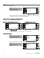
0DFUR
)LHOGEXV352),%86'3
ZLWKVDIHW\IXQFWLRQ672
',
',
',
',
',
',
)DXOW '2
$ODUP '2
$FNQRZOHGJH
5HVHUYHGIRU672
6SHHG $2
99 $,
352),%86'3
7HOHJUDP
You have to release STO, see section: Releasing "Safe Torque Off" (Page 24). For getting
the GSD file, see section: Getting the GSD file (Page 24).
Automatic / Manual - change over from field bus to jog
Factory setting with G120C DP:
0DFUR
', /2:
)LHOGEXV352),%86'3
',
',
',
',
',
',
$,
$FNQRZOHGJH
/2:
', +,*+
-RJYLD',DQG',
)DXOW '2
$ODUP '2
6SHHG $2
99 ',
',
',
',
',
',
$,
352),%86'3
7HOHJUDP
-RJVSHHG
-RJVSHHG
$FNQRZOHGJH
+,*+
)DXOW '2
$ODUP '2
6SHHG $2
99 S -RJVSHHG
S -RJVSHHG
For getting the GSD file, see section: Getting the GSD file (Page 24).
Motorized potentiometer
0DFUR
0RWRUL]HGSRWHQWLRPHWHU023
ZLWKVDIHW\IXQFWLRQ672
',
',
',
',
',
',
$,
212))
023XS
023GRZQ
$FNQRZOHGJH
5HVHUYHGIRU672
)DXOW '2
$ODUP '2
6SHHG $2
99 You have to release STO, see section: Releasing "Safe Torque Off" (Page 24).
0DFUR
0RWRUL]HGSRWHQWLRPHWHU
023
',
',
',
',
',
',
$,
212))
023XS
023GRZQ
$FNQRZOHGJH
)DXOW '2
$ODUP '2
6SHHG $2
99 Frequency inverter
16
Getting Started, 01/2011, FW 4.4, A5E02999802A AB
Installing
3.5 Pre-defined I/O-configuration
Analog setpoint
0DFUR
6DIHW\IXQFWLRQ672
',
',
',
',
',
',
$,
212))
5HYHUVH
$FNQRZOHGJH
5HVHUYHGIRU672
6HWSRLQW
,
8 99
)DXOW '2
$ODUP '2
6SHHG $2
99 You have to release STO, see section Releasing "Safe Torque Off" (Page 24).
Process industry
0DFUR
', /2:
)LHOGEXV352),%86'3
',
',
',
',
',
',
$,
([WHUQDOIDXOW
$FNQRZOHGJH
/2:
', +,*+
0RWRUL]HGSRWHQWLRPHWHU023
)DXOW '2
$ODUP '2
6SHHG $2
99 ',
',
',
',
',
',
$,
212))
([WHUQDOIDXOW
$FNQRZOHGJH
+,*+
023XS
023GRZQ
)DXOW '2
$ODUP '2
6SHHG $2
99 352),%86'3
7HOHJUDP
For getting the GSD file, see section: Getting the GSD file (Page 24).
0DFUR
', /2:
$QDORJVHWSRLQW
',
',
',
',
',
',
$,
212))
([WHUQDOIDXOW
$FNQRZOHGJH
/2:
6HWSRLQW
,
8 99
', +,*+
0RWRUL]HGSRWHQWLRPHWHU023
)DXOW '2
$ODUP '2
6SHHG $2
99 ',
',
',
',
',
',
$,
212))
([WHUQDOIDXOW
$FNQRZOHGJH
+,*+
023XS
023GRZQ
)DXOW '2
$ODUP '2
6SHHG $2
99 Frequency inverter
Getting Started, 01/2011, FW 4.4, A5E02999802A AB
17
Installing
3.5 Pre-defined I/O-configuration
Two or three wire control
Macro 12 is factory setting with the G120C USS/MB and G120C CAN.
0DFUR
7ZRZLUHFRQWURO
0RGH
&RQWUROFRPPDQG
&RQWUROFRPPDQG
212))
5HYHUVH
0RGH
0RGH
212))ULJKW 212))ULJKW
212))OHIW
212))OHIW
0DFUR
0DFUR
',
',
',
',
',
',
$,
0DFUR
0DFUR
7KUHHZLUHFRQWURO
0RGH
0RGH
&RQWUROFRPPDQG
&RQWUROFRPPDQG
&RQWUROFRPPDQG
5HOHDVH2))
21ULJKW
21OHIW
5HOHDVH2))
21
5HYHUVH
',
',
',
',
',
',
$,
&RQWUROFRPPDQG
&RQWUROFRPPDQG
$FNQRZOHGJH
6HWSRLQW
,
8 99
)DXOW '2
$ODUP '2
6SHHG $2
99 &RQWUROFRPPDQG
&RQWUROFRPPDQG
&RQWUROFRPPDQG
$FNQRZOHGJH
6HWSRLQW
,
8 99
)DXOW '2
$ODUP '2
6SHHG $2
99 Communication with the higher-level control via USS
0DFUR
)LHOGEXV866
S EDXGUDWH
S 3='QXPEHU
S 3.:QXPEHU
',
',
',
',
',
',
$,
)DXOW '2
$ODUP '2
$FNQRZOHGJH
6SHHG $2
99 866
EDXG
3='3.:YDULDEOH
You find more information on USS in the "Operating Instructions" of your inverter.
Communication with the higher-level control via CANopen
0DFUR
)LHOGEXV&$1RSHQ
S EDXGUDWH
',
',
',
',
',
',
$,
)DXOW '2
$ODUP '2
$FNQRZOHGJH
6SHHG $2
99 &$1RSHQ
N%DXG
You find more information on CANopen in the "Operating Instructions" of your inverter.
Frequency inverter
18
Getting Started, 01/2011, FW 4.4, A5E02999802A AB
4
Commissioning
Commissioning with IOP
The commissioning with the IOP can be done intuitively by using the commissioning wizards
and the help texts included in the IOP. For further information refer to the IOP Operating
Instructions.
Commissioning with STARTER
The most important steps:
● Connect the PC to the inverter via USB and start the STARTER tool.
● Choose the project wizard (menu "Project / New with assistent")
– In the project wizard choose "Find drive units online"
– Select USB as interface (Access point of the application: "DEVICE …", interface
parameter assignment used: "S7USB")
– Finish the project wizard.
● STARTER has now created your project and inserted a new drive
● Select the drive in your project and go online
● In your drive open the "Configuration" mask (double click)
● Start basic commissioning with the "Assistent" button
For further information refer to inverter operating instructions.
Commissioning with BOP-2
Remove the blind cover and snap the BOP-2 on the inverter:
,QVHUW%23
5HPRYH%23
Frequency inverter
Getting Started, 01/2011, FW 4.4, A5E02999802A AB
19
Commissioning
4.1 BOP-2 menu structure
0RWRULVVZLWFKHGRQ
2SHUDWLRQYLD%23LV
DFWLYH
0HQXOHYHOV
6HWSRLQWRUDFWXDO
YDOXHSDUDPHWHU
QXPEHURUYDOXH
)DXOWRUDODUPLVDFWLYH
-RJLVDFWLYH
6HOHFWIURPPHQX
SDUDPHWHUQXPEHUDQG
YDOXH
6ZLWFKRQDQGVZLWFK
RIIWKHPRWRU
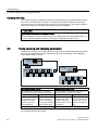
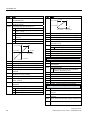
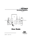
Figure 4-1
4.1
Operator control and display elements of the BOP-2
BOP-2 menu structure
021,725
OK
ESC
&21752/
OK
ESC
',$*126
OK
ESC
63 6(732,17
$&.1$//
92/7287
-2*
)$8/76
'&/1.9
5(9(56(
+,6725<
&855287
3$5$06
OK
6(783
ESC
OK
ESC
67$1'$5'
),/7(5
OK
ESC
'595(6(7
(;3(57
),/7(5
OK
(;75$6
72%23
)520%23
ESC
67$786
72&5'
)520&5'
Changing parameter values:
①
②
Parameter number freely selectable
Basic commissioning
Frequency inverter
20
Getting Started, 01/2011, FW 4.4, A5E02999802A AB
Commissioning
4.2 Basic commissioning
4.2
Basic commissioning
Menu
Remark
6(783
ESC
Set all parameters for the "SETUP" menu.
In the BOP-2, select the menu "SETUP".
OK
5(6(7
OK
&75/02'
OK
S
(8586$
S
OK
OK
027&855
OK
02732:
OK
027530
OK
S
S
S
027,'
S
Select the motor control mode. The most important control modes are:
VF LIN
V/f control with linear characteristic
VF QUAD
V/f control with square-law characteristic
SPD N EN
Closed loop speed control (vector control)
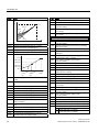
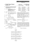
② Standard: IEC or NEMA
D-91056 Erlangen
02792/7
S
Select Reset if you wish to reset all parameters to the factory setting before the basic
commissioning: NO → YES → OK
① Voltage
③ Current
④ Power IEC standard (kW)
⑤ Power NEMA standard (HP)
⑥ Rated speed
3~Mot. 1LE10011AC434AA0
E0807/0496382_02 003
IEC/EN 60034 100L IMB3
IP55
25 kg Th.Cl. 155(F) -20°C Tamb 40°C
UNIREX-N3
Bearing
DE 6206-2ZC3 15g Intervall: 4000hrs
NE 6206-2ZC3 11g
SF 1.15 CONT NEMA MG1-12 TEFC Design A 2.0 HP
60Hz:
Hz
A
kW PF NOM.EFF rpm
V
A
CL
V
50 3.5
1.5
0.73 84.5%
400
970 380 - 420 3.55-3.55
0.73 84.5%
970 660 - 725 2.05-2.05
690 Y 50 2.05 1.5
60 3.15 1.5
0.69 86.5% 1175
K
460
Motor data on the rating plate
OK
We recommend the setting STIL ROT (Identify motor data at standstill and with the motor
rotating).
If the motor cannot rotate freely, e.g. where travel is mechanically limited, select the setting
STILL (Identify motor data at standstill).
0$&3$5
OK
0,1530
OK
5$0383
OK
5$03':1
OK
S
S
S
S
),1,6+
Select the configuration for the inputs and outputs, as well as the correct fieldbus for your
application. The predefined configurations can be found in the section titled Pre-defined I/Oconfiguration (Page 15).
Minimum motor speed.
Motor ramp-up time.
Motor ramp-down time.
OK
Confirm that the basic commissioning has been completed (Parameter p3900):
NO → YES → OK
Frequency inverter
Getting Started, 01/2011, FW 4.4, A5E02999802A AB
21
Commissioning
4.3 Freely selecting and changing parameters
Identifying motor data
If you select the MOT ID (p1900) during basic commissioning, alarm A07991 will be issued
once basic commissioning is complete. To enable the inverter to identify the data for the
connected motor, you must switch on the motor (e.g. via the BOP-2). The inverter switches
off the motor after the motor data identification has been completed.
CAUTION
Motor data identification for dangerous loads
Secure dangerous plant and system parts before starting the motor data identification, e.g.
by fencing off the dangerous location or lowering a suspended load to the floor.
4.3
Freely selecting and changing parameters
Use BOP-2 to change your inverter settings, by selecting the appropriate parameter number
and changing the parameter value. Parameter values can be changed in the "PARAMS"
menu and the "SETUP" menu.
OK
ESC OK
>2 sec
OK
OK
OK
OK
ESC
ESC
ESC
ESC
OK
OK
ESC OK
>2 sec
OK
OK
OK
ESC
ESC
ESC
OK
Select the parameter number
Changing a parameter value
If the parameter number flashes in the display,
you have two options for changing the number:
If the parameter value flashes in the display, you
have two options of changing the value:
1. option:
2. option:
1. option:
2. option:
Increase or decrease
the parameter number
using the arrow keys
until the number you
want is displayed.
Press and hold the OK
key for more than two
seconds and change
the required parameter
number digit by digit.
Increase or decrease
the parameter value
using the arrow keys
until the value you want
is displayed.
Press and hold the OK
key for more than two
seconds and enter the
required value digit by
digit.
Confirm the parameter number using the OK key.
Confirm the parameter value using the OK key.
The inverter immediately saves all changes which you made using the BOP-2 so that they
are protected against power failure.
Frequency inverter
22
Getting Started, 01/2011, FW 4.4, A5E02999802A AB
Commissioning
4.4 Changing the function of terminals
4.4
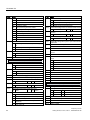
Changing the function of terminals
Terminals
Digital
inputs
Digital
outputs
',
r0722.0
',
r0722.1
',
r0722.2
',
r0722.3
',
r0722.4
',
r0722.5
BO: ryyxx.n
BI: pxxxx
p0730
'2
'2
-10 V ... 10 V
,
0 V ... 10 V
-20 mA ... 20 mA
,
0 mA ... 20 mA
r0755
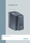
1. Select the desired function
indicated by a "BI"parameter.
Function: Switch on the motor with DI 2.
Setting: p0840 = 722.2
',
8
p0756[0]
8
CI: pyyyy
1. Select the desired function
indicated by a "BO"parameter.
212))
p2103
722.1
r0722.1
Function: Signal "fault" on DO 1.
Setting: p0731 = 52.3
2. Set the parameter p073x
of the desired digital output
to the value of the "BO"parameter.
1. Select the desired function
indicated by a "CI"parameter.
p0840
722.2
r0722.2
Function: Acknowledge faults with DI 1.
Setting: p3981 = 722.1
',
p0731
$,
Examples
2. Set this parameter to the
value of the status
parameter r0722.x of the
desired digital input.
Analog
input
Changing the function
r0052.3
p0731
52.3
'2
Function: AI 0 provides setpoint for the
PID controller.
Setting: p2253 = 55[0]
2. Set this parameter to the
value of the status
parameter r0755 of the
analog input.
$,
r0755
p2253
755.0
Use p0756[0] and the I/U switch on the inverter front for adjusting the
analog input as voltage or current input.
Analog
output
p0776[0]
CO: rxxyy
0 V ... 10 V
0 mA ... 20 mA
p0771
$2
1. Select the desired function
indicated by a "CO"parameter.
Function: Signal "current" on AO 0.
Setting: p0771 = 27
2. Set the parameter p0771
of the analog output to the
value of the "CO"parameter.
|i|
r0027
p0771
27
$2
Use p0776[0] for adjusting the analog input as voltage or current input.
Frequency inverter
Getting Started, 01/2011, FW 4.4, A5E02999802A AB
23
Commissioning
4.5 Releasing "Safe Torque Off"
4.5
Releasing "Safe Torque Off"
Terminals
Set the following parameters for releasing STO:
Fail-safe
digital input
p9761 = …
Enter password for fail-safe function (factory setting = 0)
p9762 = …
Enter new password, if required (0 … FFFF FFFF)
',
',
4.6
672
p9763 = …
Confirm new password
p0010 = 95
Enter commissioning of fail-safe functions
p9601 = 1
STO is selected via terminal strip
p9659 = …
Set the forced checking procedure timer (8 h … 1 year).
To fulfill the requirements of standards EN 954-1, ISO 13849-1
and IEC 61508 regarding timely error detection, the inverter
must regularly test its safety-relevant circuits to ensure that they
function correctly.
p9700 = 208
Copy fail-safe parameters
p9701 = 220
Confirm fail-safe parameters
p0010 = 0
Finish commissioning of fail-safe functions
Getting the GSD file
The GSD is a description file for a PROFIBUS slave. You have two options for obtaining the
GSD of your inverter:
1. You can find the SINAMICS inverter GSD on the Internet
(http://support.automation.siemens.com/WW/view/en/22339653/133100).
2. The GSD is saved in the inverter. The inverter writes its GSD to the memory card if you
insert the memory card in the inverter and set p0804 to 12. Using the memory card, you
can then transfer the GSD to your PG/your PC.
Frequency inverter
24
Getting Started, 01/2011, FW 4.4, A5E02999802A AB
Parameter list
5
P-No.
The following list contains the basic parameter
information with access level 1 … 3. The complete
parameter list is provided in the list manual, see
Further information (Page 44).
P-No.
Note
2SHUDWLRQDQGYLVXDOL]DWLRQ
Note
.01
Ready
.02
Operation enabled
.03
Fault active
.04
Coast down active (OFF2)
.05
Quick stop active (OFF3)
.06
Closing lockout active
.07
Alarm active
.08
Deviation, setpoint/actual speed
.09
Control requested
.10
Maximum speed reached
.11
I,M,P limit reached
.12
Motor holding brake open
Alarm overtemperature motor
r0002
Drive operating display
.13
p0003
Access level
.14
Motor rotates forwards
p0010
Drive, commissioning parameter filter
.15
Alarm converter overload
p0015
Macro drive unit
r0053
CO/BO: Status word 2
See also Pre-defined I/O-configuration (Page 15).
r0054
CO/BO: Control word 1
r0018
Control Unit firmware version
.00
ON/OFF1
r0020
Speed setpoint smoothed [100 % ≙ p2000]
.01
OFF2
r0021
CO: Actual speed smoothed [100 % ≙ p2000]
.02
OFF3
r0022
Speed actual value rpm smoothed [rpm]
.03
Enable ramp-function generator
r0024
Output frequency smoothed [100 % ≙ p2000]
.04
Enable ramp-function generator
r0025
CO: Output voltage smoothed [100 % ≙ p2001]
.05
Continue ramp-function generator
r0026
CO: DC link voltage smoothed [100 % ≙ p2001]
.06
Enable speed setpoint
r0027
CO: Absolute actual current smoothed
[100 % ≙ p2002]
.07
Acknowledge fault
.08
Jog bit 0
r0031
Actual torque smoothed [100 % ≙ p2003]
.09
Jog bit 1
r0032
CO: Active power actual value smoothed
[100 % ≙ r2004]
.10
Master control by PLC
.11
Direction reversal (setpoint)
.13
Motorized potentiometer, raise
r0034
Motor utilization [1 ≙ 100 %]
r0035
CO: Motor temperature [100 °C ≙ 100 %]
r0036
CO: Power unit overload I2t [1 ≙ 100 %]
r0039
Energy consumption
1
Reset the energy consumption display
p0040
Reset energy consumption display
r0041
Energy usage saved/energy saved
p0045
Smoothing time constant, display values [ms]
r0046
CO/BO: Missing enable signals
r0047
Motor data identification routine and speed
controller optimization
r0050
CO/BO: Command Data Set CDS effective
r0051
CO/BO: Drive Data Set DDS effective
r0052
CO/BO: Status word 1
.00
Ready to start
r0055
.14
Motorized potentiometer, lower
.15
CDS bit 0
CO/BO: Supplementary control word
.00
Fixed setpoint, bit 0
.01
Fixed setpoint, bit 1
.02
Fixed setpoint, bit 2
.03
Fixed setpoint, bit 3
.04
DDS selection, bit 0
.05
DDS selection, bit 1
.08
Technology controller enable
.09
DC braking enable
.11
Droop enable
.12
Closed-loop torque control active
Frequency inverter
Getting Started, 01/2011, FW 4.4, A5E02999802A AB
25
Parameter list
P-No.
P-No.
Note
.13
Note
External fault 1 (F07860)
r0208
Rated power unit line supply voltage [V]
.15
CDS bit 1
r0209
Power unit, maximum current
r0056
CO/BO: Status word, closed-loop control
p0210
Drive unit line supply voltage [V]
r0060
CO: Speed setpoint before setpoint filter
[100 % ≙ p2000]
p0230
Drive filter type, motor side
r0062
CO: Speed setpoint after filter [100 % ≙ p2000]
r0063
CO: Speed actual value unsmoothed
[100 % ≙ p2000]
r0064
CO: Speed controller system deviation
[100 % ≙ p2000]
r0065
Slip frequency [100 % ≙ p2000]
r0066
CO: Output frequency [100 % ≙ p2000]
r0067
CO: Output current, maximum [100 % ≙ p2002]
r0068
CO: Absolute current actual value unsmoothed
[100 % ≙ p2002]
r0070
CO: Actual DC link voltage [100 % ≙ p2001]
r0071
Maximum output voltage [100 % ≙ p2001]
r0072
CO: Output voltage [100 % ≙ p2001]
r0075
CO: Current setpoint field-generating
[100 % ≙ p2002]
r0076
CO: Current actual value field-generating
[100 % ≙ p2002]
r0077
CO: Current setpoint torque-generating
[100 % ≙ p2002]
r0078
CO: Current actual value torque-generating
[100 % ≙ p2002]
r0079
CO: Torque setpoint, total [100 % ≙ p2003]
&RPPLVVLRQLQJ
p0100
IEC/NEMA motor standard
0
IEC motor (50 Hz, SI units)
1
NEMA motor (60 Hz, US units)
2
NEMA motor (60 Hz, SI units)
p0170
Number of Command Data Sets (CDS)
p0180
Number of Drive Data Sets (DDS)
3RZHU0RGXOH
p0233
0
No filter
1
Motor reactor
2
dv/dt filter
3
Siemens sine-wave filter
4
Sine wave filter, third-party manufacturer
Power unit motor reactor [mH]
p0234
Power unit sine-wave filter capacitance [µF]
r0238
Internal power unit resistance
p0278
DC link voltage undervoltage threshold reduction
[V]
p0287
Ground fault monitoring thresholds
[100 % ≙ r0209]
r0289
CO: Maximum power unit output current
[100 % ≙ p2002]
p0290
Power unit overload response
0
Reduce output current or output frequency
1
No reduction, shutdown when overload
threshold is reached
2
Reduce I_output or f_output and f_pulse (not
using I2t).
3
Reduce the pulse frequency (not using I2t)
p0292
Power unit temperature alarm threshold [°C]
p0295
Fan run-on time [s]
0RWRU
p0300
Motor type selection
0
No motor
1
Induction motor
2
Synchronous motor
17 1LA7 standard induction motor
p0301
Motor code number selection
p0304
Rated motor voltage [V]
Rated motor current [A]
p0201
Power unit code number
p0305
r0204
Power unit, hardware properties
p0306
Number of motors connected in parallel
p0205
Power unit application
p0307
Rated motor power [kW]
0
Load cycle with high overload
p0308
Rated motor power factor
1
Load cycle with light overload
p0309
Rated motor efficiency [%]
Rated motor frequency [Hz]
Rated motor speed [rpm]
r0206
Rated power unit power [kw/hp]
p0310
r0207
Rated power unit current
p0311
Frequency inverter
26
Getting Started, 01/2011, FW 4.4, A5E02999802A AB
Parameter list
P-No.
Note
p0320
Motor rated magnetizing current/short-circuit
current [A]
p0322
Maximum motor speed [rpm]
p0323
Maximum motor current [A]
r0330
Rated motor slip
r0331
Actual motor magnetizing current/short-circuit
current
p0335
Motor cooling type
p0340
Automatic calculation of motor/control parameters
p0341
Motor moment of inertia [kgm²]
p0342
Ratio between the total and motor moment of
inertia [kgm²]
p0604
r0345
Nominal motor starting time
p0605
Motor temperature fault threshold [°C]
p0346
Motor excitation build-up time [s]
p0610
Motor overtemperature response
p0347
Motor de-excitation time [s]
p0350
Motor stator resistance, cold [Ω]
1
Alarm with reduction of Imax and fault
p0352
Cable resistance [Ω]
2
Alarm and fault, no reduction of Imax
r0395
Actual stator resistance
p0611
I2t motor model thermal time constant [s]
Actual rotor resistance
p0615
I2t motor model fault threshold [°C]
p0625
Motor ambient temperature [°C]
p0637
Q flux, flux gradient saturated [mH]
p0640
Current limit [A]
r0396
P-No.
p0596
Technology application
p0505
Selecting the system of units
43 ft wg
45 % r.h.
46 g/kg
44 m wg
Reference quantity, technological units
7KHUPDOPRWRUPRQLWRULQJDQGPRWRUPRGHO
PD[LPXPFXUUHQW
p0601
Motor temperature sensor type
0
No sensor
1
PTC warning & timer
2
KTY84
4
Bimetallic NC contact warning & timer
Motor temperature alarm threshold [°C]
0
7HFKQRORJ\DQGXQLWV
p0500
Note
42 inch wg
No response, alarm only, no reduction of Imax
&RPPDQGVRXUFHVDQGWHUPLQDOVRQWKH&RQWURO8QLW
1
System of units SI
2
Referred system of units/SI
p0700
Command source selection
3
US system of units
r0720
CU number of inputs and outputs
4
System of units, referred/US
r0722
CO/BO: CU digital inputs, status
p0573
Inhibit automatic reference value calculation
.00
DI 0 (terminal 5)
p0595
Selecting technological units
.01
DI 1 (terminal 6)
1
%
2
1 referred, no dimensions
.02
DI 2 (terminal 7)
3
bar
4
°C
5
Pa
.03
DI 3 (terminal 8)
6
ltr/s
7
m³/s
8
ltr/min
.04
DI 4 (terminal 16)
DI 5 (terminal 17)
DI 11 (terminals 3, 4) AI 0
10 ltr/h
11 m³/h
.05
12 kg/s
13 kg/min
14 kg/h
.11
15 t/min
16 t/h
17 N
r0723
CO/BO: CU digital inputs, status inverted
18 kN
19 Nm
20 psi
p0730
BI: CU signal source for terminal DO 0
21 °F
22 gallon/s
23 inch³/s
9
m³/min
NO: Terminal 19 / NC: Terminal 18
p0731
BI: CU signal source for terminal DO 1
24 gallon/min
25 inch³/min
26 gallon/h
27 inch³/h
28 lb/s
29 lb/min
30 lb/h
31 lbf
32 lbf ft
r0747
CU, digital outputs status
CU, invert digital outputs
BO: CU analog inputs status word
NO: Terminal 21
33 K
34 rpm
35 parts/min
p0748
36 m/s
37 ft³/s
38 ft³/min
r0751
39 BTU/min
40 BTU/h
41 mbar
Frequency inverter
Getting Started, 01/2011, FW 4.4, A5E02999802A AB
27
Parameter list
P-No.
Note
r0752
CO: CU analog inputs input voltage/current actual
AI0 (terminals 3/4)
P-No.
r0755
CO: CU analog inputs actual value in percent, AI0
(terminals 3/4) [%]
p0756
CU analog input type (terminals 3, 4)
Note
\ S
9P$
\ S
0
Unipolar voltage input (0 V ... +10 V)
1
Unipolar voltage input monitored
(+2 V... +10 V)
2
Unipolar current input (0 mA … +20 mA)
p0777
3
Unipolar current input monitored (+4 mA …
+20 mA)
p0778
CU analog output characteristic value y1 [V]
p0779
CU analog output characteristic value x2 [%]
4
Bipolar voltage input (-10 V...+10 V)
p0780
CU analog output characteristic value y2 [V]
8
No sensor connected
p0782
BI: CU analog output invert signal source, AO 0
(terminals 12,13)
\ S
[ S
r0785
CU analog output characteristic value x1 [%]
BO: CU analog outputs status word
.00
p0795
[ S
[ S
1 = AO 0 negative
CU digital inputs, simulation mode
9P$
p0796
CU digital inputs, simulation mode setpoint
[ S
p0797
CU analog inputs, simulation mode
p0798
CU analog inputs, simulation mode setpoint
&KDQJHRYHUDQGFRS\GDWDVHWV
\ S
CU analog input characteristic value x1
p0802
Data transfer with memory card as source/target
p0758
CU analog input characteristic value y1 [%]
p0803
p0759
CU analog input characteristic value x2
Data transfer with device memory as
source/target
p0760
CU analog input characteristic value y2 [%]
p0761
CU analog input wire break monitoring response
threshold
p0771
CI: CU analog output signal source, AO 0
(terminals 12, 13) [1 ≙ 100%]
p0806
BI: Inhibit master control
r0807
BO: Master control active
r0772
CU analog output, output value currently referred
p0809
Copy Command Data Set CDS
r0774
CU analog output, output voltage/current actual
[100% ≙ p2001]
p0810
BI: Command data set selection CDS bit 0
p0775
CU analog output activate absolute value
generation
r0835
CO/BO: Data set changeover status word
r0836
CO/BO: Command data set CDS selected
p0776
CU analog output type
p0757
0
Current output (0 mA ... +20 mA)
1
Voltage output (0 V... +10 V)
2
Current output (+4 mA ... +20 mA)
p0804
Data transfer start
12 Start transfer of the GSD for PROFIBUS
master on the memory card
6HTXHQFHFRQWUROHJ212))
p0840
BI: ON/OFF (OFF1)
p0844
BI: No coast down/coast down (OFF2) signal
source 1
p0845
BI: No coast down/coast down (OFF2) signal
source 2
p0848
BI: No quick stop/quick stop (OFF3) signal source
1
p0849
BI: No quick stop/quick stop (OFF3) signal source
1
Frequency inverter
28
Getting Started, 01/2011, FW 4.4, A5E02999802A AB
Parameter list
P-No.
Note
p0852
BI: Operation enable
P-No.
1
Save drive object
p0854
BI: Master control by PLC
10
Save in a non-volatile memory as setting
10
11
Save in a non-volatile memory as setting
11
12
Save in a non-volatile memory as setting
12
p0855
BI: Unconditionally release holding brake
p0856
BI: Enable speed controller
p0858
BI: Unconditionally close holding brake
r0898
CO/BO: Control word sequence control
r0899
CO/BO: Status word sequence control
p0972
Note
Drive unit reset
352),%86352),GULYH
p0918
PROFIBUS address
p0922
PROFIdrive telegram selection
1
Standard telegram 1, PZD-2/2
20
Standard telegram 20, PZD-2/6
352
SIEMENS telegram 352, PZD-6/6:
353
SIEMENS telegram 353, PZD-2/2, PKW4/4
354
SIEMENS telegram 354, PZD-6/6, PKW4/4
999
Free telegram configuration with BICO
)DXOWV3DUW
6HWSRLQWFKDQQHO
p1000
Speed setpoint selection
p1001
CO: Fixed speed setpoint 1 [rpm]
p1002
CO: Fixed speed setpoint 2 [rpm]
p1003
CO: Fixed speed setpoint 3 [rpm]
p1004
CO: Fixed speed setpoint 4 [rpm]
p1005
CO: Fixed speed setpoint 5 [rpm]
p1006
CO: Fixed speed setpoint 6 [rpm]
p1007
CO: Fixed speed setpoint 7 [rpm]
p1008
CO: Fixed speed setpoint 8 [rpm]
p1009
CO: Fixed speed setpoint 9 [rpm]
p1010
CO: Fixed speed setpoint 10 [rpm]
r0944
CO: Counter for fault buffer changes
p1011
CO: Fixed speed setpoint 11 [rpm]
r0945
Fault code
p1012
CO: Fixed speed setpoint 12 [rpm]
r0946
Fault code list
p1013
CO: Fixed speed setpoint 13 [rpm]
r0947
Fault number
p1014
CO: Fixed speed setpoint 14 [rpm]
r0948
Fault time received in milliseconds [ms]
p1015
CO: Fixed speed setpoint 15 [rpm]
r0949
Fault value
p1016
Fixed speed setpoint mode
p0952
Fault cases, counter
1
Direct selection
r0963
PROFIBUS baud rate
2
Selection, binary coded
p0965
PROFIdrive profile number
p1020
BI: Fixed speed setpoint selection bit 0
p0969
System runtime relative [ms]
p1021
BI: Fixed speed setpoint selection bit 1
p1022
BI: Fixed speed setpoint selection bit 2
5HVWRULQJWKHIDFWRU\VHWWLQJ
6DYLQJSDUDPHWHUV
p0970
p0971
Reset drive parameters
0
Inactive
1
Reset start parameters
5
Starts a safety parameter reset
10
Starts to download setting 10
11
Starts to download setting 11
12
Starts to download setting 12
100
Starts a BICO interconnection reset
Save parameters
0
Inactive
p1023
BI: Fixed speed setpoint selection bit 3
r1024
CO: Fixed speed setpoint effective [100 % ≙
p2000]
r1025
BO: Fixed speed setpoint status
p1030
Motorized potentiometer configuration
p1035
00
Storage active
01
Automatic operation, ramp-function
generator active
02
Initial rounding active
03
Storage in NVRAM active
BI: Motorized potentiometer setpoint raise
Frequency inverter
Getting Started, 01/2011, FW 4.4, A5E02999802A AB
29
Parameter list
P-No.
Note
p1036
BI: Motorized potentiometer setpoint lower
p1037
Motorized potentiometer maximum speed [rpm]
p1038
Motorized potentiometer minimum speed [rpm]
p1040
Motorized potentiometer start value [rpm]
p1043
BI: Motorized potentiometer, accept setting value
p1044
CI: Motorized potentiometer setting value [100 %
≙ p2000]
p1047
Motorized potentiometer ramp-up time [s]
p1048
Motorized potentiometer ramp-down time [s]
r1050
CO: Motorized potentiometer setpoint after the
ramp-function generator [100 % ≙ p2000]
p1055
BI: Jog bit 0
p1056
BI: Jog bit 1
p1058
Jog 1 speed setpoint [rpm]
p1059
Jog 2 speed setpoint [rpm]
p1070
CI: Main setpoint [100 % ≙ p2000]
p1071
CI: Main setpoint scaling [1 ≙ 100 %]
r1073
CO: Main setpoint effective [100 % ≙ p2000]
p1075
CI: Supplementary setpoint [100 % ≙ p2000]
p1076
CI: Supplementary setpoint scaling [1 ≙ 100 %]
r1077
CO: Supplementary setpoint effective
[100 % ≙ p2000]
r1078
CO: Total setpoint effective [100 % ≙ p2000]
p1080
Minimum speed [rpm]
p1082
Maximum speed [rpm]
p1083
CO:Speed limit in positive direction of rotation
[rpm]
r1084
CO: Speed limit positive effective [100 % ≙
p2000]
p1086
CO: Speed limit in negative direction of rotation
[rpm]
r1087
CO: Speed limit negative effective [100 % ≙
p2000]
p1091
Skip speed 1 [rpm]
p1092
Skip speed 2 [rpm]
p1101
Skip speed bandwidth [rpm]
p1110
BI: Inhibit negative direction
p1111
BI: Inhibit positive direction
p1113
BI: Setpoint inversion
r1114
CO: Setpoint after the direction limiting [100 % ≙
p2000]
r1119
CO: Ramp-function generator setpoint at the input
[100 % ≙ p2000]
P-No.
Note
Q
QPD[
3
6HWSRLQW
3
3
W
p1120
Ramp-function generator ramp-up time [s]
p1121
Ramp-function generator ramp-down time [s]
p1130
Ramp-function generator initial rounding-off time
[s]
p1131
Ramp-function generator final rounding-off time
[s]
p1134
Ramp-function generator rounding-off type
0
Continuous smoothing
1
Discontinuous smoothing
p1135
OFF3 ramp-down time [s]
p1136
OFF3 initial rounding-off time [s]
p1137
OFF3 final rounding-off time [s]
p1140
BI: Ramp-function generator enable
p1141
BI: Continue ramp-function generator
p1142
BI: Speed setpoint enable
r1149
CO: Ramp-function generator acceleration
[100 % ≙ p2007]
r1170
CO: Speed controller setpoint sum
[100 % ≙ p2000]
r1198
CO/BO: Control word, setpoint channel
)XQFWLRQVHJPRWRUKROGLQJEUDNH
p1200
Flying restart operating mode
0
Flying restart inactive
1
Flying restart always active (start in setpoint
direction)
4
Flying restart always active (start only in
setpoint direction)
p1201
BI: Flying restart enable signal source
p1202
Flying restart search current [100 % ≙ r0331]
p1203
Flying restart search rate factor [%]
A higher value results in a longer search time.
p1206
Set fault number without automatic restart
p1210
Automatic restart mode
0
Inhibit automatic restart
1
Acknowledge all faults without restarting
Frequency inverter
30
Getting Started, 01/2011, FW 4.4, A5E02999802A AB
Parameter list
P-No.
Note
4
Restart after line supply failure, without
additional start attempts
6
Restart after fault with additional start
attempts
P-No.
26 Acknowledging all faults and restarting for an
ON command
p1211
Automatic restart, start attempts
p1212
Automatic restart, delay time start attempts [s]
p1213
Automatic restart, monitoring time [s]
p1215
Motor holding brake configuration
0
No motor holding brake being used
3
Motor holding brake like sequential control,
connection via BICO
p1216
Motor holding brake, opening time [ms]
p1217
Motor holding brake, closing time [ms]
p1230
BI: DC braking activation
p1231
DC braking configuration
0
No function
4
DC braking
14 DC braking below starting speed
p1232
DC braking, braking current [A]
p1233
DC braking time [s]
p1234
Speed at the start of DC braking [rpm]
r1239
CO/BO: DC braking status word
p1240
VDC controller or VDC monitoring configuration
(vector control)
0
Inhibit VDC controller
1
Enable VDC_max controller
2
Enable VDC_min controller (kinetic buffering)
3
Enable VDC_min controller and VDC_max
controller
Automatic detection enabled
p1255
VDC_min controller time threshold [s]
p1256
VDC_min controller response (kinetic buffering)
14 Restart after line supply failure following
manual acknowledgement
16 Restart after fault following manual
acknowledgement
Note
1
0
Buffer VDC until undervoltage, n<p1257 →
F07405
1
Buffer VDC until undervoltage, n<p1257 →
F07405, t>p1255 → F07406
p1257
VDC_min controller speed threshold [rpm]
p1280
VDC controller or VDC monitoring configuration
(V/f)
0
Inhibit VDC controller
1
Enable VDC_max controller
2
Enable VDC_min controller (kinetic buffering)
3
Enable VDC_min controller and VDC_max
controller
r1282
VDC_max controller switch-in level (V/f) [100 % ≙
p2001]
p1283
VDC_max controller dynamic factor (V/f) [%]
p1285
VDC_min controller switch-in level (kinetic buffering)
(V/f) [%]
r1286
VDC_min controller switch-in level (kinetic buffering)
(V/f) [100 % ≙ p2001]
p1287
VDC_min controller dynamic factor (kinetic
buffering) (V/f) [%]
p1294
VDC_max controller automatic detection ON signal
level (V/f)
1
Automatic detection enabled
9IFRQWURO
p1300
Open-loop/closed-loop control operating mode
0
V/f control with linear characteristic
1
V/f control with linear characteristic and FCC
2
V/f control with parabolic characteristic
3
V/f control with parameterizable
characteristic
4
V/f control with linear characteristic and ECO
5
V/f control for drive requiring a precise
frequency (e.g. textiles)
r1242
VDC_max controller switch-in level [100 % ≙ p2001]
p1243
VDC_max controller dynamic factor [%]
p1245
VDC_min controller switch-in level (kinetic buffering)
[%]
6
V/f control for drive requiring a precise
frequency and FCC
r1246
VDC_min controller switch-in level (kinetic buffering)
[100 % ≙ p2001]
7
V/f control for parabolic characteristic and
ECO
p1247
VDC_min controller dynamic factor (kinetic
buffering) [%]
19 V/f control with independent voltage setpoint
p1249
VDC_max controller speed threshold [rpm]
p1254
VDC_max controller automatic ON level detection
20 Speed control (without encoder)
Frequency inverter
Getting Started, 01/2011, FW 4.4, A5E02999802A AB
31
Parameter list
P-No.
Note
8
8Q
P-No.
Note
p1340
Imax frequency controller proportional gain
p1341
Imax frequency controller integral time [s]
r1343
CO: I_max controller frequency output
[100 % ≙ p2000]
p1351
CO: Motor holding brake starting frequency
[1 ≙ 100 %]
p1352
CI: Motor holding brake starting frequency
[1 ≙ 100 %]
3
3
9HFWRUFRQWURO
3
r1438
CO: Speed controller speed setpoint
[100 % ≙ p2000]
p1452
Speed controller speed actual value smoothing
time (SLVC) [ms]
p1470
Speed controller encoderless operation P gain
p1472
Speed controller sensorless operation integral
time [ms]
p1475
CI: Speed controller torque setting value for motor
holding brake [100 % ≙ p2003]
r1482
CO: Speed controller I torque output
[100 % ≙ p2003]
S8
r1493
CO: Moment of inertia, total
S8
S8
U
p1496
Acceleration pre-control scaling [%]
IQ
I
p1310
Voltage boost permanent [100 % ≙ p0305]
p1311
Voltage boost when accelerating [%]
p1312
Voltage boost when starting [%]
r1315
Voltage boost, total [100 % ≙ p2001]
8
U
S8
S
S
I
I
I
S
S
S
I
I
+]
p1320
V/f control programmable characteristic frequency
1 [Hz]
p1321
V/f control programmable characteristic voltage 1
[V]
p1322
Characteristic frequency 2 [Hz]
p1323
Characteristic voltage 2 [V]
p1324
Characteristic frequency 3 [Hz]
p1325
Characteristic voltage 3 [V]
p1326
Characteristic frequency 4 [Hz]
p1511
CI: Supplementary torque 1 [100 % ≙ p2003]
r1516
CO: Supplementary torque and acceleration
torque [100 % ≙ p2003]
p1520
CO: Torque limit upper [Nm]
p1521
CO: Torque limit lower [Nm]
p1522
CI: Torque limit upper [100 % ≙ p2003]
p1523
CI: Torque limit lower [100 % ≙ p2003]
p1524
CO: Torque limit upper/motoring scaling
[1 ≙ 100 %]
p1525
CO: Torque limit lower scaling [1 ≙ 100 %]
r1526
CO: Torque limit upper without offset
[100 % ≙ p2003]
r1527
CO: Torque limit lower without offset
[100 % ≙ p2003]
p1327
Characteristic voltage 4 [V]
p1530
Power limit motoring [kW]
p1330
CI: V/f control independent voltage setpoint
[100 % ≙ p2001]
p1531
Power limit regenerative [kW]
p1334
V/f control slip compensation starting frequency
[Hz]
r1538
CO: Upper effective torque limit [100 % ≙ p2003]
r1539
CO: Lower effective torque limit [100 % ≙ p2003]
r1547
CO: Torque limit for speed controller output
p1335
Slip compensation, scaling [100 % ≙ r0330]
p1336
Slip compensation limit value [100 % ≙ r0330]
r1337
CO: Actual slip compensation [1 ≙ 100 %]
p1338
V/f mode resonance damping gain
[0] Upper limit [100 % ≙ p2003]
[1] Lower limit [100 % ≙ p2003]
Frequency inverter
32
Getting Started, 01/2011, FW 4.4, A5E02999802A AB
Parameter list
P-No.
Note
P-No.
Note
p1552
CI: Torque limit upper scaling without offset
[1 ≙ 100 %]
p2000
Reference speed reference frequency [rpm]
p1554
CI: Torque limit lower scaling without offset
[1 ≙ 100 %]
p2001
Reference voltage [V]
p2002
Reference current [A]
p2003
Reference torque [Nm]
r2004
Reference power
p2006
Reference temperature [°C]
p2010
Commissioning interface baud rate
p1570
CO: Flux setpoint [1 ≙ 100 %]
p1571
CI: Supplementary flux setpoint [100 % ≙ p2003]
p1580
Efficiency optimization [%]
r1598
CO: Flux setpoint total [1 ≙ 100 %]
p1610
Torque setpoint static (SLVC) [100 % ≙ r0333]
p1611
Supplementary accelerating torque (SLVC)
[100 % ≙ r0333]
r1732
CO: Direct-axis voltage setpoint [100 % ≙ p2001]
r1733
CO: Quadrature-axis voltage setpoint
[100 % ≙ p2001]
p1745
Motor model error threshold stall detection [%]
p1784
Motor model feedback scaling [%]
p2011
Commissioning interface address
p2016
CI: Comm IF USS PZD send word
866RU0RGEXV578
p2020
*DWLQJXQLW
Fieldbus interface baud rate:
4
2400 baud
5
4800 baud
6
9600 baud
7
19200 baud
8
38400 baud
9
57600 baud
10 76800 baud
11 93750 baud
12 115200 baud
13 187500 baud
Pulse frequency setpoint [kHz]
p2021
r1801
CO: Pulse frequency [100 % ≙ p2000]
p2022
Fieldbus interface USS PZD number
p1820
Reverse the output phase sequence
p2023
Fieldbus interface USS PKW number
p1800
1
On
0RWRULGHQWLILFDWLRQ
p1900
Motor data identification and rotating
measurement
0
Inhibited
1
Identify the motor data at standstill and with
the motor rotating
2
Identify motor data at standstill
3
Identify motor data with the motor rotating
p1909
Motor data identification control word
p1910
Motor data identification selection
p1959
Rotating measurement configuration
p1960
Rotating measurement selection
0
Inhibited
1
Rotating measurement in encoderless
operation
3
Speed controller optimization in encoderless
operation
p1961
Saturation characteristic speed to determine [%]
p1965
Speed_ctrl_opt speed [100 % ≙ p0310]
p1967
Speed_ctrl_opt dynamic factor [%]
5HIHUHQFHYDOXHV
p2024
Fieldbus interface address
0
PKW 0 words
3
PKW 3 words
4
PKW 4 words
127
PKW variable
Fieldbus interface times [ms]
[0] Maximum processing time
[1] Character delay time
[2] Telegram pause time
r2029
Fieldbus interface error statistics
[0] Number of error-free telegrams
[1] Number of rejected telegrams
[2] Number of framing errors
[3] Number of overrun errors
[4] Number of parity errors
[5] Number of starting character errors
[6] Number of checksum errors
[7] Number of length errors
p2030
r2032
Fieldbus interface protocol selection
0
No protocol
1
USS
2
MODBUS
3
PROFIBUS
4
CAN
Master control, control word effective
Frequency inverter
Getting Started, 01/2011, FW 4.4, A5E02999802A AB
33
Parameter list
P-No.
p2037
Note
.00
ON / OFF1
.01
OFF2 inactive
p2040
Note
r2055
PROFIBUS diagnosis standard
[0] Master bus address
.02
OFF3 inactive
[1] Master input total length bytes
.03
Operation enable
[2] Master output total length bytes
.04
Ramp-function generator enable
.05
Start ramp-function generator
.06
Speed setpoint enable
.07
Acknowledge fault
.08
Jog bit 0
.09
Jog bit 1
.10
Master control by PLC
r2074
r2076
Freeze setpoints and sign-of-life
2
Setpoints are not frozen
p2079
VIK-NAMUR
p2080
Fieldbus interface monitoring time [ms]
r2043
SINAMICS
2
VIK-NAMUR
Setpoint failure
.02
Fieldbus operational
p2047
PROFIBUS additional monitoring time [ms]
r2050
CO: PROFIdrive PZD receive word
Binector-connector converter, invert status word
r2089
CO: Send binector-connector converter status
word
[0] Status word 1
…
[7] PZD 8
r2090
BO: PROFIdrive PZD1 receive bit-serial
r2091
BO: PROFIdrive PZD2 receive bit-serial
r2092
BO: PROFIdrive PZD3 receive bit-serial
r2093
BO: PROFIdrive PZD4 receive bit-serial
r2094
BO: Connector-binector converter binector output
r2095
BO: Connector-binector converter binector output
)DXOWV3DUWDQGDODUPV
CI: PROFIdrive PZD send word
…
[7] PZD 8
PROFIdrive diagnostics send PZD word
[0] PZD 1
r2054
BI: Binector-connector converter, status word 1
[4] Free status word 5
PROFIdrive fault delay [s]
r2053
PROFIdrive PZD telegram selection extended
[3] Free status word 4
.00
[0] PZD 1
[7] PZD 8
[2] Free status word 3
p2044
p2051
…
PROFIBUS diagnostics peer-to-peer data transfer
addresses
[1] Status word 2
BO: PROFIdrive PZD state
[0] PZD 1
PROFIdrive diagnostics telegram offset PZD send
p2088
PROFIBUS ID Number
0
[7] PZD 8
The individual bits are combined to form status
word 1.
352),%86352),GULYH
p2042
…
See p0922
PROFIdrive STW/ZSW interface mode
2
[7] PZD 8
PROFIdrive diagnostics telegram offset PZD
receive
[0] PZD 1
r2077
1
SINAMICS
…
[0] PZD 1
Freeze setpoints and further process sign-oflife
0
PROFIdrive diagnostics bus address PZD receive
[0] PZD 1
r2075
PROFIdrive STW1.10 = 0 mode
0
p2038
P-No.
…
[7] PZD 8
p2100
Setting the fault number for fault response
p2101
Setting the fault response
PROFIBUS status
0
OFF
1
No connection (search for baud rate)
2
Connection OK (baud rate found)
3
Cyclic connection with master (data
exchange)
4
Cyclic data OK
0
None
1
OFF1
2
OFF2
3
OFF3
5
STOP2
6
DC braking
p2103
BI: 1. Acknowledge faults
p2104
BI: 2. Acknowledge faults
p2106
BI: External fault 1
r2110
Alarm number
Frequency inverter
34
Getting Started, 01/2011, FW 4.4, A5E02999802A AB
Parameter list
P-No.
Note
P-No.
Note
p2111
Alarm counter
p2220
BI: Techn. controller fixed value selection bit 0
p2112
BI: External alarm 1
p2221
BI: Techn. controller fixed value selection bit 1
r2122
Alarm code
p2222
BI: Techn. controller fixed value selection bit 2
r2123
Alarm time received [ms]
p2223
BI: Techn. controller fixed value selection bit 3
r2124
Alarm value
r2224
r2125
Alarm time removed [ms]
CO: Techn. controller fixed value active [1 ≙
100%]
p2126
Setting fault number for acknowledge mode
r2225
p2127
Sets acknowledgement mode
CO/BO: Techn. controller fixed value selection
status word
p2128
Selecting fault/alarm code for trigger
r2129
CO/BO: Trigger word for faults and alarms
r2130
Fault time received in days
r2133
Fault value for float values
r2134
Alarm value for float values
r2135
CO/BO: Status word, faults/alarms 2
r2136
Fault time removed in days
r2138
CO/BO: Control word, faults/alarms
r2139
CO/BO: Status word, faults/alarms 1
r2169
CO: Actual speed smoothed signals
r2197
CO/BO: Status word monitoring functions 1
r2198
CO/BO: Status word monitoring 2
r2199
CO/BO: Status word monitoring 3
7HFKQRORJ\FRQWUROOHU
r2229
Techn. controller number currently
p2230
Techn. controller motorized potentiometer
configuration
.00
Storage active
.02
Initial rounding active
.03
Non-volatile data save active for
p2230.0 = 1
.04
Ramp-function generator always active
r2231
Techn. controller motorized potentiometer
setpoint memory
p2235
BI: Techn. controller motorized potentiometer
setpoint up
p2236
BI: Techn. controller motorized potentiometer
setpoint down
p2237
Techn. controller motorized potentiometer
maximum value [%]
p2238
Techn. controller motorized potentiometer
minimum value [%]
p2240
Techn. controller motorized potentiometer start
value [%]
r2245
CO: Techn. controller motorized potentiometer
setpoint before RFG [1 ≙ 100%]
p2247
Techn. controller motorized potentiometer rampup time [s]
p2248
Techn. controller motorized potentiometer rampdown time [s]
r2250
CO: Techn. controller motorized potentiometer
setpoint after RFG [1 ≙ 100%]
p2251
Techn. controller mode
p2200
BI: Technology controller enable
p2201
CO: Techn. controller fixed value 1 [1 ≙ 100%]
p2202
CO: Techn. controller fixed value 2 [1 ≙ 100%]
p2203
CO: Techn. controller fixed value 3 [1 ≙ 100%]
p2204
CO: Techn. controller fixed value 4 [1 ≙ 100%]
p2205
CO: Techn. controller fixed value 5 [1 ≙ 100%]
p2206
CO: Techn. controller fixed value 6 [1 ≙ 100%]
p2207
CO: Techn. controller fixed value 7 [1 ≙ 100%]
p2208
CO: Techn. controller fixed value 8 [1 ≙ 100%]
p2209
CO: Techn. controller fixed value 9 [1 ≙ 100%]
p2210
CO: Techn. controller fixed value 10 [1 ≙ 100%]
p2211
CO: Techn. controller fixed value 11 [1 ≙ 100%]
0
Techn. controller as main speed setpoint
p2212
CO: Techn. controller fixed value 12 [1 ≙ 100%]
1
p2213
CO: Techn. controller fixed value 13 [1 ≙ 100%]
Techn. controller as additional speed
setpoint
p2214
CO: Techn. controller fixed value 14 [1 ≙ 100%]
p2215
CO: Techn. controller fixed value 15 [1 ≙ 100%]
p2216
Techn. controller fixed value selection method
0
Fixed value selection direct
1
Fixed value selection binary
p2253
CI: Techn. controller setpoint 1 [1 ≙ 100%]
p2254
CI: Techn. controller setpoint 2 [1 ≙ 100%]
p2255
Techn. controller setpoint 1 scaling [%]
p2256
Techn. controller setpoint 2 scaling [%]
p2257
Techn. controller ramp-up time [s]
p2258
Techn. controller ramp-down time [s]
Frequency inverter
Getting Started, 01/2011, FW 4.4, A5E02999802A AB
35
Parameter list
P-No.
Note
r2260
CO: Techn. controller setpoint after ramp function
generator [1 ≙ 100%]
P-No.
p2261
Techn. controller setpoint filter time constant [s]
p2263
Techn. controller type
0
D component in the actual value signal
1
D component in the fault signal
Note
1
Inversion of the techn. controller fault signal
r2344
CO: Techn. controller last speed setpoint
(smoothed) [1 ≙ 100%]
p2345
Techn. controller fault response
0
Function inhibited
1
For a fault: change over to r2344 (or p2302)
2
For a fault: Change over to p2215
p2264
CI: Techn. controller actual value [1 ≙ 100%]
p2265
Techn. controller actual value filter time constant
[s]
r2349
CO/BO: Techn. controller status word
r2266
CO: Techn. controller actual value after filter [1 ≙
100%]
p2900
CO: Fixed value 1 [%]
p2901
CO: Fixed value 2 [%]
p2267
Techn. controller upper limit actual value [1 ≙
100%]
r2902
CO: Fixed values [%]
p2930
CO: Fixed value M [Nm]
p2268
Techn. controller lower limit actual value [1 ≙
100%]
p2269
Techn. ontroller gain actual value [%]
p2270
Techn. controller actual value function selection
p2271
0
No function
1
√x
2
x²
3
x³
0HVVDJHV
r3113
CO/BO: NAMUR message bit bar
0RWRUFKDUDFWHULVWLF
p3320
Techn. controller actual value inversion (sensor
type)
Fluid flow machine P = f(n), Y coordinate: P flow
1%, point 1
p3321
1
Fluid flow machine P = f(n), X coordinate: n flow
1%, point 1
p3322
P = f(n), Y coordinate: P flow 2%, point 2
p3323
P = f(n), X coordinate: n flow 2%, point 2
p3324
P = f(n), Y coordinate: P flow 3%, point 3
In version of the technology controller actual
value signal
r2272
CO: Techn. controller actual value scaled [1 ≙
100%]
r2273
CO: Techn. controller error [1 ≙ 100%]
p3325
P = f(n), X coordinate: n flow 3%, point 3
p2274
Techn. controller actual differentiation time
constant [s]
p3326
P = f(n), Y coordinate: P flow 4%, point 4
p3327
P = f(n), X coordinate: n flow 4%, point 4
p2280
Techn. controller proportional gain
p3328
P = f(n), Y coordinate: P flow 5%, point 5
p2285
Techn. controller integral time [s]
p3329
P = f(n), X coordinate: n flow 5%, point 5
p2286
BI: Hold techn. controller integrator
p2289
CI: Techn. controller pre-control signal [1 ≙ 100%]
p2291
CO: Techn. controller maximum limit [1 ≙ 100%]
p2292
CO: Techn. controller minimum limit [1 ≙ 100%]
p2293
Techn. controller ramp-up/ramp-down time [s]
r2294
CO: Techn. controller output signal [1 ≙ 100%]
p2295
CO: Techn. controller output scaling [1 ≙ 100%]
p2296
CI: Techn. controller output scaling [1 ≙ 100%]
p2297
CI: Techn. controller maximum limit signal source
[1 ≙ 100%]
p2298
CI: Techn. controller minimum limit signal source
[1 ≙ 100%]
p2299
CI: Techn. controller limit offset [1 ≙ 100%]
p2302
Techn. controller output signal start value [%]
p2306
Techn. controller fault signal inversion
7ZRWKUHHZLUHFRQWURO
p3330
BI: 2-3 wire control 1
p3331
BI: 2-3 wire control 2
p3332
BI: 2-3 wire control 3
r3333
CO/BO: 2-3 wire output
p3334
.00
2-3 wire ON
.01
2-3 wire reverse
.02
2-3 wire ON / invert
.03
2-3 wire reverse/invert
2-3 wire selection
0
No 2-3 wire control
1
2-wire forward/backward 1
2
2-wire forward/backward 2
Frequency inverter
36
Getting Started, 01/2011, FW 4.4, A5E02999802A AB
Parameter list
P-No.
Note
P-No.
Note
3
3-wire enable / forward / backward
p8685
CAN NMT state
4
3-wire enable / ON / reverse
p8699
CAN RPDO monitoring time [ms]
p8700
CAN Receive PDO 1 [hex]
p8701
CAN Receive PDO 2 [hex]
p8702
CAN Receive PDO 3 [hex]
p8703
CAN Receive PDO 4 [hex]
p8704
CAN Receive PDO 5 [hex]
p8705
CAN Receive PDO 6 [hex]
p8706
CAN Receive PDO 7 [hex]
p8707
CAN Receive PDO 8 [hex]
p8710
CAN Receive Mapping for RPDO 1 [hex]
p8711
CAN Receive Mapping for RPDO 2 [hex]
p8712
CAN Receive Mapping for RPDO 3 [hex]
p8713
CAN Receive Mapping for RPDO 4 [hex]
p8714
CAN Receive Mapping for RPDO 5 [hex]
p8715
CAN Receive Mapping for RPDO 6 [hex]
p8716
CAN Receive Mapping for RPDO 7 [hex]
p8717
CAN Receive Mapping for RPDO 8 [hex]
p8720
CAN Transmit PDO 1 [hex]
p8721
CAN Transmit PDO 2 [hex]
p8722
CAN Transmit PDO 3 [hex]
p8723
CAN Transmit PDO 4 [hex]
p8724
CAN Transmit PDO 5 [hex]
p8725
CAN Transmit PDO 6 [hex]
p8726
CAN Transmit PDO 7 [hex]
p8727
CAN Transmit PDO 8 [hex]
p8730
CAN Transmit Mapping for TPDO 1 [hex]
p8731
CAN Transmit Mapping for TPDO 2 [hex]
p8732
CAN Transmit Mapping for TPDO 3 [hex]
p8733
CAN Transmit Mapping for TPDO 4 [hex]
p8734
CAN Transmit Mapping for TPDO 5 [hex]
p8735
CAN Transmit Mapping for TPDO 6 [hex]
p8736
CAN Transmit Mapping for TPDO 7 [hex]
&RPSRXQGEUDNLQJ
p3856
Compound braking current [%]
r3859
CO/BO: Compound braking status word
$GPLQLVWUDWLRQSDUDPHWHUV
p3900
Completion of quick commissioning
r3925
Identification final display
p3950
Service parameters
p3981
Faults, acknowledge drive object
p3985
Master control mode selection
r3996
Parameter write inhibit status
p7760
Adjustable parameters write protection
1
r8570
Active
Macro drive object
&$1RSHQ
r8600
CAN Device Type
r8601
CAN Error Register
p8602
CAN SYNC-Object
p8603
CAN COB-ID Emergency Message [hex]
p8604
CAN Node Guarding
p8606
CAN Producer Heartbeat Time [ms]
r8607
CAN Identity Object
p8608
CAN Clear Bus Off Error
p8609
CAN Error Behavior
r8610
CAN First Server SDO
p8611
CAN Pre-defined Error Field [hex]
p8620
CAN Node-ID
r8621
CAN Node-ID effective
p8622
CAN bit rate [kBit/s]
0
1000
1
800
2
500
3
250
4
125
5
50
6
20
7
10
p8623
CAN Bit Timing selection [hex]
p8630
CAN virtual objects
p8641
CAN Abort Connection Option Code
0
No response
1
OFF1
2
OFF2
3
OFF3
r8680
CAN Diagnosis Hardware
p8684
CAN NMT state after booting
p8737
CAN Transmit Mapping for TPDO 8 [hex]
p8741
CAN PDO configuration acknowledgment
p8744
CAN PDO Mapping Configuration
1:
Predefined connection set
2:
Free PDO mapping
r8750
CAN mapped receive objects 16 bit
r8751
CAN mapped receive objects 16 bit
r8784
CO: CAN status word
p8785
BI: CAN status word bit 8
Frequency inverter
Getting Started, 01/2011, FW 4.4, A5E02999802A AB
37
Parameter list
P-No.
Note
P-No.
Note
p8786
BI: CAN status word bit 14
r9773
CO/BO: SI status (processor 1 + processor 2)
p8787
BI: CAN status word bit 15
r9780
SI monitoring clock cycle (processor 1)
p8790
CAN control word - auto interconnection
r9781
SI checksum to check changes (processor 1)
r8795
CAN control word
r9782
SI time stamp to check changes (processor 1)
r8797
CAN Target Torque
r9794
SI crosswise comparison list (processor 1)
r9795
SI diagnostics, STOP F (processor 1)
r9798
SI actual checksum SI parameters (processor 1)
p9799
SI reference checksum SI parameters (processor
1)
p9801
SI enable, functions integrated in the drive
(processor 2)
Safely remove memory card
p9810
SI PROFIsafe address (processor 2)
0
No memory card inserted
p9850
SI F-DI changeover, tolerance time (processor 2)
1
Memory card inserted
p9851
SI STO debounce time (processor 2)
2
Request "safe removal" of the memory
card
r9871
SI common functions (processor 2)
3
"Safe removal" possible
r9872
CO/BO: SI status (Power Module)
100
"Safe removal" not possible due to access
r9898
SI actual checksum SI parameters (processor 2)
p9899
SI reference checksum SI parameters (processor
2)
352),GULYH
r8820
Identification and Maintenance 0
p8991
USB memory access
3DUDPHWHUFRQVLVWHQF\DQGVWRUDJH
p9400
r9401
Safely remove memory card status
r9463
Set valid macro
p9484
BICO interconnections, search signal source
r9485
BICO interconnections, search signal source
number
r9486
BICO interconnections, search signal source first
index
'LDJQRVWLFVLQWHUQDO
r9976
System utilization
[1] Computation time utilization
[5] Highest gross utilization
6DIHW\,QWHJUDWHG
p9601
SI enable, functions integrated in the drive
(processor 1)
p9610
SI PROFIsafe address (processor 1)
p9650
SI F-DI changeover, tolerance time (processor 1)
[ms]
p9651
SI STO debounce time (processor 1) [ms]
p9659
SI forced checking procedure timer [h]
r9660
SI forced checking procedure remaining time
p9700
SI copy function
p9701
Acknowledge SI data change
p9761
SI password input [hex]
p9762
SI password new [hex]
p9763
SI password acknowledgment [hex]
r9770
SI version, safety functions integrated in the drive
(processor 1)
r9771
SI common functions (processor 1)
r9772
CO/BO: SI status (processor 1)
Frequency inverter
38
Getting Started, 01/2011, FW 4.4, A5E02999802A AB
6
Trouble shooting
6.1
List of alarms and faults
Axxxxx Alarm
Fyyyyy: Fault
Table 6- 1
The most important alarms and faults of the safety functions
Number
Cause
Remedy
F01600
STOP A initiated
Select STO and then deselect again
F01650
Acceptance test required
Carry out acceptance test and create test certificate.
F01659
Write task for parameter rejected Cause: A parameter reset was selected. The fail-safe parameters have not
yet been reset, as the safety functions are enabled
Switch the Control Unit off and then on again.
Remedy: block safety functions or reset fail-safe parameters (p0970 = 5),
then reset the drive parameters once again.
A01666
Static 1 signal on the F-DI for
secure acknowledgement
Setting F-DI to logical 0 signal
A01698
Commissioning mode active for
safety functions
This message is withdrawn after the safety functions have been
commissioned
A01699
Shutdown path test required
After the next time that the "STO" function is deselected, the message is
withdrawn and the monitoring time is reset
F30600
STOP A initiated
Select STO and then deselect again
Table 6- 2
The most important alarms and faults
Number
Cause
Remedy
F01018
Power-up aborted more than
once
1. Switch the module off and on again.
2. After this fault has been output, the module is booted with the factory
settings.
3. Recommission the inverter.
A01028
Configuration error
Explanation: Parameterization on the memory card has been created with a
different type of module (order number, MLFB)
Check the module parameters and recommission if necessary.
F01033
Unit switchover: Reference
parameter value invalid
Set the value of the reference parameter not equal to 0.0 (p0304, p0305,
p0310, p0596, p2000, p2001, p2002, p2003, r2004).
F01034
Unit switchover: Calculation of
the parameter values after
reference value change
unsuccessful
Select the value of the reference parameter so that the parameters involved
can be calculated in the per unit notation (p0304, p0305, p0310, p0596,
p2000, p2001, p2002, p2003, r2004).
F01122
Frequency at the probe input too Reduce the frequency of the pulses at the probe input.
high
Frequency inverter
Getting Started, 01/2011, FW 4.4, A5E02999802A AB
39
Trouble shooting
6.1 List of alarms and faults
Number
Cause
Remedy
A01590
Motor maintenance interval
lapsed
Carry out the maintenance.
A01900
PROFIBUS: Configuration
telegram faulty
Explanation: A PROFIBUS master is attempting to establish a connection
with a faulty configuration telegram.
Check the bus configuration on the master and slave side.
F01910
Fieldbus SS setpoint timeout
Check the bus connection and communication partner, e.g. switch the
PROFIBUS master to the RUN status.
A01920
PROFIBUS: Cyclic connection
interrupt
Explanation: The cyclic connection to PROFIBUS master is interrupted.
Analog input, wire break
Check the connection to the signal source for interrupts.
Check the level of the signal supplied.
The input current measured by the analog input can be read out in r0752.
A03520
Temperature sensor fault
Check that the sensor is connected correctly.
A05000
A05001
A05002
A05004
A05006
Power Module overtemperature
Check the following:
- Is the ambient temperature within the defined limit values?
- Are the load conditions and duty cycle configured accordingly?
- Has the cooling failed?
F06310
Supply voltage (p0210)
incorrectly parameterized
Check the parameterized supply voltage and if required change (p0210).
F07011
Motor overtemperature
Reduce the motor load.
F03505
Establish the PROFIBUS connection and activate the PROFIBUS master
with cyclic operation.
Check the line voltage.
Check ambient temperature.
Check sensor's wiring and connection.
A07012
I2t Motor Module
overtemperature
Check and if necessary reduce the motor load.
Check the motor's ambient temperature.
Check thermal time constant p0611.
Check overtemperature fault threshold p0605.
A07015
Motor temperature sensor alarm
Check that the sensor is connected correctly.
Check the parameter assignment (p0601).
F07016
Motor temperature sensor fault
Make sure that the sensor is connected correctly.
F07086
F07088
Unit switchover: Parameter limit
violation
Check the adapted parameter values and if required correct.
F07320
Automatic restart aborted
Increase the number of restart attempts (p1211). The current number of
start attempts is shown in r1214.
Check the parameterization (p0601).
Increase the wait time in p1212 and/or monitoring time in p1213.
Create ON command (p0840).
Increase the monitoring time of the power unit or switch off (p0857).
Reduce the wait time for resetting the fault counter p1213[1] so that fewer
faults are registered in the time interval.
A07321
Automatic restart active
Explanation: The automatic restart (AR) is active. During voltage recovery
and/or when remedying the causes of pending faults, the drive is
automatically switched back on.
F07330
Search current measured too
low
Increase search current (P1202), check motor connection.
Frequency inverter
40
Getting Started, 01/2011, FW 4.4, A5E02999802A AB
Trouble shooting
6.1 List of alarms and faults
Number
Cause
Remedy
A07400
VDC_max controller active
If the controller is not to intervene:
A07409
F07426
F07801
V/f control current limiting
controller active
Increase the ramp-down times.
Deactivate the VDC_max controller (p1240 = 0 for vector control, p1280 = 0
for V/f control).
The alarm automatically disappears after one of the following measures:
Increase the current limit (p0640).
Reduce load.
Increase the ramp-up time to the speed setpoint.
Technology controller actual
value limited
Adapt the limits to the signal level (p2267, p2268).
Check the actual value scaling (p2264).
Motor overcurrent
Check current limits (p0640).
U/f control: Check the current limiting controller (p1340 … p1346).
Increase acceleration ramp (p1120) or reduce load.
Check motor and motor cables for short circuit and ground fault.
Check motor for star-delta connection and rating plate parameterization.
Check power unit / motor combination.
Select flying restart function (p1200) if switched to rotating motor.
A07805
A07850
Drive: Power unit overload I2t
External alarm 1
Reduce the continuous load.
Adapt the load cycle.
Check the assignment of rated currents of the motor and power unit.
The signal for "external alarm 1" has been triggered.
Parameter p2112 defines the signal source of the external alarm.
Remedy: Rectify the cause of this alarm.
F07901
Motor overspeed
Activate precontrol of the speed limiting controller (p1401 bit 7 = 1).
F07902
Motor stalled
Check whether the motor data has been parameterized correctly and
perform motor identification.
Check the current limits (p0640, r0067, r0289). If the current limits are too
low, the drive cannot be magnetized.
Check whether motor cables are disconnected during operation.
A07910
Motor overtemperature
Check the motor load.
Check the motor's ambient temperature.
Check the KTY84 sensor.
A07920
Torque/speed too low
The torque deviates from the torque/speed envelope curve.
A07921
Torque/speed too high
Check the connection between the motor and the load.
A07922
Torque/speed out of tolerance
Adapt the parameterization corresponding to the load.
F07923
Torque/speed too low
Check the connection between the motor and the load.
Adapt the parameterization corresponding to the load.
F07924
Torque/speed too high
A07927
DC braking active
Not required
A07980
Rotary measurement activated
Not required
Frequency inverter
Getting Started, 01/2011, FW 4.4, A5E02999802A AB
41
Trouble shooting
6.1 List of alarms and faults
Number
Cause
Remedy
A07981
No enabling for rotary
measurement
Acknowledge pending faults.
A07991
Motor data identification
activated
Switch on the motor and identify the motor data.
F30001
Overcurrent
Check the following:
Establish missing enables (see r00002, r0046).
Motor data, if required, carry out commissioning
Motor's connection method (Υ / Δ)
U/f operation: Assignment of rated currents of motor and Power Module
Line quality
Make sure that the line commutating reactor is connected properly
Power cable connections
Power cables for short-circuit or ground fault
Power cable length
Line phases
If this doesn't help:
F30005
I2t inverter overload
U/f operation: Increase the acceleration ramp
Reduce the load
Replace the power unit
Check the rated currents of the motor and Power Module.
Reduce current limit p0640.
When operating with U/f characteristic: Reduce p1341.
F30011
Line phase failure
F30015
Motor cable phase failure
F30021
Ground fault
Check the inverter's input fuses.
Check the motor cables.
Check the motor cables.
Increase the ramp-up or ramp-down time (p1120).
Check the power cable connections.
Check the motor.
Check the current transformer.
Check the cables and contacts of the brake connection (a wire might be
broken).
F30027
Time monitoring for DC link precharging
Check the supply voltage on the input terminals.
F30035
Overtemperature, intake air
Check whether the fan is running.
F30036
Overtemperature, inside area
Check the fan filter elements.
Check whether the ambient temperature is in the permissible range.
F30037
Rectifier overtemperature
Check the line voltage setting (p0210).
See F30035 and, in addition:
Check the motor load.
Check the line phases
A30049
Internal fan defective
Check the internal fan and if required replace.
F30059
Internal fan defective
Check the internal fan and if required replace.
Frequency inverter
42
Getting Started, 01/2011, FW 4.4, A5E02999802A AB
Trouble shooting
6.1 List of alarms and faults
Number
Cause
Remedy
A30502
DC link overvoltage
Check the device supply voltage (p0210).
Check the line reactor dimensioning
A30920
Temperature sensor fault
Check that the sensor is connected correctly.
For further information, please refer to the List Manual.
Frequency inverter
Getting Started, 01/2011, FW 4.4, A5E02999802A AB
43
Trouble shooting
6.2 Further information
6.2
Table 6- 3
Further information
Technical Support
France
Germany
Italy
Spain
United Kingdom
+33 (0) 821 801 122
+49 (0)911 895 7222
+39 (02) 24362000
+34 902 237 238
+44 161 446 5545
Further service telephone numbers: Product support (http://support.automation.siemens.com/WW/view/en/4000024)
Table 6- 4
Manuals with further information
Information
level
Manual
Content
Available
languages
Download or order number
+
Getting Started
(this manual)
++
Operating instructions - Installing, commissioning and
inverter
operating the inverter.
Description of inverter
functions.
Technical data.
English,
German,
Italian,
French,
Spanish,
Turkish,
Chinese
Documentation download
(http://support.automation.siemens.c
om/WW/view/en/36426537/133300)
+++
Function Manual Safety Configuring PROFIsafe.
Integrated
Installing, commissioning and
operating the integrated failsafe function.
+++
List manual
+++
Operating instructions - Description of operator panel
BOP-2, IOP
Table 6- 5
English,
German
Complete list of parameters,
alarms and faults.
Graphic function block
diagrams.
Order numbers:
SD Manual Collection (DVD)
6SL3298-0CA00-0MG0
Supplied once
6SL3298-0CA10-0MG0
Update service for 1 year;
supplied 4 times
Spare parts
Order number
Spare part kit including 5 sets I/O terminals, 1 door set and 1 blind cover
6SL3200-0SK40-0AA0
Screening plates
Frame size A
6SL3266-1EA00-0KA0
Frame size B
6SL3266-1EB00-0KA0
Frame size C
6SL3266-1EC00-0KA0
Frame size A
6SL3200-0ST05-0AA0
1 set of connector plugs (mains, motor and breaking
resistor)
Fan units
Top cover with built in fan
Frame size B
6SL3200-0ST06-0AA0
Frame size C
6SL3200-0ST07-0AA0
Frame size A
6SL3200-0SF12-0AA0
Frame size B
6SL3200-0SF13-0AA0
Frame size C
6SL3200-0SF14-0AA0
Frame size A
6SL3200-0SF40-0AA0
Frame size B
6SL3200-0SF41-0AA0
Frame size C
6SL3200-0SF42-0AA0
Frequency inverter
44
Getting Started, 01/2011, FW 4.4, A5E02999802A AB
Siemens AG
Industry Sector
Drive Technologies
Motion Control Systems
Postfach 3180
91050 ERLANGEN
GERMANY
We reserve the right to make technical
changes.
© Siemens AG 2011
www.siemens.com/sinamics-g120