1
&$1RSHQ,PSOHPHQWDWLRQ*XLGHOLQHV
by G.Gruhler(Ed.) and Bernd Dreier
STA Reutlingen, Germany
Version 2.3
STA-Fax Contact: +49- (0) 71 21-2 57 13
Internet: http://www.fh-reutlingen.de/~www-sta
ESPRIT Project 22171 &$1RSHQ
7DEOHRI&RQWHQWV
35()$&( 5()(5(1&(6 */266$5< &$123(1%$6,&6$1'29(59,(: '$7$7<3(6 &$/$1'&$123(1 1(7:25.0$1$*(0(17,1&$123(1 7.1 NMT START REMOTE NODE (6) ......................................................................................................... 14
7.2 NMT ENTER PRE-OPERATIONAL STATE (8)......................................................................................... 15
7.3 NMT STOP REMOTE NODE (7) ........................................................................................................... 15
7.4 NMT RESET NODE (10) ..................................................................................................................... 16
7.5 NMT RESET COMMUNICATION (11) .................................................................................................... 16
7.6 NODE GUARDING ............................................................................................................................... 17
6(59,&('$7$2%-(&7 352&(66'$7$2%-(&7 1(7:25.6<1&+521,=$7,21 %22783 (0(5*(1&<0(66$*(86$*( +$5':$5($63(&76&$1&21752//(560,&52&21752//(5 ,'',675,%87,21,1$&$123(11(7:25. &$123(1'(9,&(352),/(6 $'',7,21$/)5(48(17/<$6.('48(67,216 01.07.1997
2
Implguid_public.doc STA Reutlingen
3UHIDFH
Since CANopen communication and device profiles are available the influence of this CAN
communication standard is increasing throughout the CAN in automation arena.
The technology transfer center STA in Reutlingen has been strongly involved in the CANopen
development from the very beginning. The know-how gained in many CANopen activities and
implementations is the base for this document.
The aim of the document is :
• assistance for manufacturers in implementing CANopen in their devices,
• additional aspects for CANopen implementations,
• give background information,
• suggestions for details which are intentionally left open by the specification,
• answering frequently asked questions.
This document does not intend to replace the CANopen communication profile specification and the
device profiles, it will give additional information in order to clarify the CANopen communication profile
and the device profile. Therefore we assume that the reader is on getting familiar with the CANopen
communication profile.
As it is planned to improve the document, comments will be appreciated and welcome by fax(see
cover sheet).
01.07.1997
3
Implguid_public.doc STA Reutlingen
5HIHUHQFHV
/1/:
ISO 7498, 1984, Information Processing Systems - Open Systems Interconnection Basic
Reference Model
/2/:
CiA/DS 301, CANopen CAL-based Communication Profile for Industrial Systems, October 1996,
Version 3.0
/3/:
ISO/DIS 11898, 1992, Road Vehicles, Interchange of Digital Information - Controller Area
Network (CAN) for high-speed Communication
/4/:
Robert Bosch GmbH, CAN Specification 2.0 Part B, September 1991
/5/:
CiA/DS 102, CAN Physical Layer for Industrial Applications, April 1994
/6/:
CiA/DS 201, CAN Reference Model, February 1996
/7/:
CiA/DS 202-1, CMS Service Specification, February 1996
/8/:
CiA/DS 202-2, CMS Protocol Specification, February 1996
/9/:
CiA/DS 202-3, CMS Encoding Rules, February 1996
/10/: CiA/DS 203-1, NMT Service Specification, February 1996
/11/: CiA/DS 203-2, NMT Protocol Specification, February 1996
/12/: CiA/DS 204-1, DBT Service Specification, February 1996
/13/: CiA/DS 204-2, DBT Protocol Specification, February 1996
/14/: CiA/DS 207, Application Layer Naming Specification, February 1996
/15/: CiA/DS 205-1, LMT Service Specification, February 1996
/16/: CiA/DS 205-2, LMT Protocol Specification, February 1996
/17/: CiA/DSP 401, Device Profile for I/O Modules, December 1996
/18/: CiA/WD 302, Framework for Programmable Devices, not yet published
/19/: CiA/WD 402, CAL based device Profile for Drives, May 1997
/20/: CiA/WD 404, Device Profile for Measuring Devices and Closed Loop Controllers, not yet
published
/21/: CiA/WD 405, CANopen Device Profile for Programmable Controllers, not yet published
/22/: CiA/WD 406, CANopen Device Profile for Encoders, May 1997
/23/: CiA/WD 407, CANopen Device Profile for Public Transport, not yet published
01.07.1997
4
Implguid_public.doc STA Reutlingen
*ORVVDU\
&L$
CAN in Automation international users and manufacturers group e.V..
&06
CAN based Message Specification. One of the service elements of the CAN Application
Layer in the CAN Reference Model.
&2%
Communication Object. (CAN Message) A unit of transportation in a CAN Network. Data
must be sent across a network inside a COB.
&2%,'
COB-Identifier. Identifies a COB uniquely in a network. The identifier determines the
priority of that COB in the MAC sub-layer too.
'%7
Distributor. One of the service elements of the application in the CAN Reference Model.
Its the responsibility of the DBT to distribute COB-ID’s to the COB’s that are used by CMS.
/07
Layer Management. One of the service elements of the application in the CAN Reference
Model. It serves to configure parameters of each layer in the CAN Reference Model.
107
Network Management. One of the service elements of the application in the CAN
Reference Model. It performs initialisation, configuration and error handling in a CAN
network.
3'2
Process Data Object. Object for process data exchange between several CANopen
devices
6'2
Service Data Object. Peer to peer communication with access to the Object Dictionary of
a CANopen device.
'6
Draft Standard
'63
Draft Standard Proposal
:'
Working Draft
01.07.1997
5
Implguid_public.doc STA Reutlingen
&$1RSHQEDVLFVDQGRYHUYLHZ
The CANopen profile family was developed to define standardized communication mechanisms and
device functionality for CAN based devices. The profile family consists of a communication profile /2/
and various standardized device profiles /17/, /19/../23/. The CANopen communication profile utilizes a
subset of CAN Application Layer /6/../16/ for efficient real-time communication.
The central concept of CANopen is the usage of an object dictionary, this represents the
communication and application related data. To access the data, two mechanisms are supported these
are:
• Process Data Objects(PDO)
• Service Data Objects(SDO)
The PDO mechanism is used to transmit real time data, which has to be transmitted quickly, preferable
without any overhead, and with predefined structure. This process data is either transmitted in a cyclic,
synchronous manner or asynchronously, event driven. Typical data content is I/O or command/actual
values for drives.
Secondly there is the parameter communication which has different requirements: parameters have to
be confirmed, they may consist of many bytes and then have to be split in several segments,
parameters are typically transmitted asynchronously, and the requirements towards transmission times
are moderate. It has to be possible to include address information in order to access a specific
parameter out of a parameter list; therefore the SDO mechanism is used.
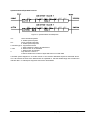
3URFHVV'DWD2EMHFW
6HUYLFH'DWD2EMHFW
8VHGIRU5HDO7LPH'DWD
8VHGIRU1RQ5HDO7LPH'DWD
6\ QFKURQRXV0HVVDJHVDQG
$V\ QFKURQRXV0HVVDJHV
,QWHUUXSWGULYHQ0HVVDJHV
/RZHU3ULRULW\ ,GHQWLILHUV
+LJK3ULRULW\ ,GHQWLILHUV
2SWLPLVHGIRU+LJK6SHHG
'DWD([FKDQJH
&RQILUPHG6HUYLFHV
PD[%\ WHVSHU
0XOWL7HOHJUDP0HVVDJHV3RVVLEOH
)RUPDWPXVWEHQHJRWLDWHG
8VHV,QGH[LQJWR5HIHUHQFH'DWD
EHWZHHQ&RPPXQLFDWLRQ
)LHOGVLQ2EMHFW'LFWLRQDU\
3DUWQHUV
Figure 1: Communication Mechanism
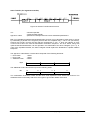
All device parameters are listed in an object dictionary. This object dictionary contains the description,
data type and structure of the parameter as well as the address. The following table shows an extract
of an object dictionary.
01.07.1997
6
Implguid_public.doc STA Reutlingen
,QGH[KH[
6XE,QGH[
2EMHFW
1DPH
7\SH
$WWU
VAR
VAR
VAR
RECORD
VAR
VAR
ARRAY
VAR
VAR
VAR
VAR
VAR
VAR
VAR
VAR
VAR
VAR
device type
error register
manufacturer status register
predefined error field
error counter
standard error field
number of PDOs supported
COB-ID SYNC-message
communication cycle period
synchronous window length
manufacturer device name
manufacturer hardware version
manufacturer software version
Node-ID
guard time
life time factor
COB-ID guarding protocol
Unsigned32
Unsigned8
Unsigned32
Unsigned32
Unsigned8
Unsigned32
Unsigned32
Unsigned32
Unsigned32
Unsigned32
Vis-String
Vis-String
Vis-String
Unsigned32
Unsigned32
Unsigned32
Unsigned32
const
ro
ro
ro
ro
ro
rw
rw
rw
const
const
const
ro
rw
rw
rw
0
1
2
3
4
RECORD
VAR
VAR
VAR
VAR
VAR
1st receive PDO communication parameter
number of entries
COB-ID used by PDO
transmission type
inhibit time
CMS priority group
PDOComPar
Unsigned8
Unsigned32
Unsigned8
Unsigned16
Unsigned8
ro
rw
rw
rw
rw
0
1
...
8
ARRAY
VAR
VAR
VAR
VAR
1st receive PDO mapping parameter
number of mapped objects in PDO
1st object to be mapped
nth object to be mapped
8th object to be mapped
PDOMapping
Unsigned32
Unsigned32
Unsigned32
Unsigned32
ro
rw
rw
rw
0
1
2
3
4
RECORD
VAR
VAR
VAR
VAR
VAR
1st transmit PDO communication parameter
number of entries
COB-ID used by PDO
transmission type
inhibit time
CMS priority group
PDOComPar
Unsigned8
Unsigned32
Unsigned8
Unsigned16
Unsigned8
ro
rw
rw
rw
rw
0
1
...
8
ARRAY
VAR
VAR
VAR
VAR
1st transmit PDO mapping parameter
number of mapped objects in PDO
1st object to be mapped
nth object to be mapped
8th object to be mapped
PDOMapping
Unsigned32
Unsigned32
Unsigned32
Unsigned32
ro
rw
rw
rw
1000
1001
1002
1003
0
1
1004
1005
1006
1007
1008
1009
100A
100B
100C
100D
100E
::
1400
::
1600
::
1800
::
1A00
Figure 2: CANopen Object Dictionary
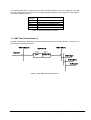
The object dictionary is organized in a communication profile specific part which contains the
communication entries, and in a device specific part which contains the device entries. The device
specific part is specified in the device profile, the communication entries form the common subset of all
devices, therefore they are specified in the communication profile. There is a range of mandatory
entries in the dictionary which ensure that all CANopen devices of a particular type show the same
basic behavior. The object dictionary concept caters for optional device features which means a
manufacturer does not have to provide certain extended functionality on his device but if he wishes to
do so he must do it in a pre-defined fashion. Additionally, there is sufficient address space for truly
manufacturer specific functionality. This approach ensures that the CANopen device profiles are
“future-proof”.
01.07.1997
7
Implguid_public.doc STA Reutlingen
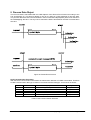
Figure 3: Object Dictionary Structure
The CANopen device profiling provides a non-manufacturer specific part with upward compatibility. By
defining mandatory device characteristics basic network operation is guaranteed. By defining optional
device features a degree of defined flexibility can be built in. By leaving “hooks” for manufacturer
specific functionality vendors will not be constrained to an out-of-date standard.
01.07.1997
8
Implguid_public.doc STA Reutlingen
'DWD7\SHV
The base data types which are supported by CANopen are defined in the document DS202-3 "CMS
Data Types and Encoding Rules". The basic data types are described next.
%22/($1
The Boolean data type is used to store information which attains the values TRUE and FALSE. The
values are encode in one byte.
Value Encoding:
TRUE = FFH
FALSE = 0H
,QWHJHU
The Integer8data type is used to store one byte signed values.
Value Range:
-80H - 7FH
-128 - 127
,QWHJHU
The Integer16data type is used to store two byte signed values.
Value Range:
-8000H - 7FFFH
32768 - 32767
LSB
MSB
Low
High
Byte
Byte
,QWHJHU
The Integer32data type is used to store four byte signed values.
Value Range:
-80000000 H - 7FFFFFFFH
-2147483648 - 2147483647
LSB
MSB
Byte 0
Byte1
Byte2
Byte3
Data
Data
Data
Data
8QVLJQHG
The Unsigned8data type is used to store one byte unsigned values.
Value Range:
01.07.1997
0H - FFH
0 - 255
9
Implguid_public.doc STA Reutlingen
8QVLJQHG
The Unsigned16data type is used to store two byte unsigned values.
Value Range:
0H - FFFFH
0 - 65536
LSB
MSB
Low
High
Byte
Byte
8QVLJQHG
The Unsigned32 data type is used to store four byte unsigned values.
Value Range:
0H - FFFFFFFFH
0 - 4294967295
LSB
MSB
Byte 0
Byte1
Byte2
Byte3
Data
Data
Data
Data
)ORDW
The Floatdata type is used to store four byte real values. The encoding of the values is according to
the IEEE 754-1985 standard.
1HZ'DWD7\SH'HILQLWLRQV
New data types have to be defined in the object dictionary section for "Manufacturer Specific Data
Types". If a new complex data type is defined, the sub-index 0 should describe the number of entries in
the structure and the following entries should store the data.
The following example defines a new complex data type. The new data type is called information
structure. It is used to store the actual sensor value and status information of a multichannel closed
loop controller.
Information Structure:
Index
41
Sub-Index
0
1
2
3
Field
Data Type
number of supported entries in the Unsigned8
record
channel number
Unsigned8
actual value
Integer16
status information
Unsigned8
Table 1: Information Structure
01.07.1997
10
Implguid_public.doc STA Reutlingen
&$/DQG&$1RSHQ
CAN Application Layer (CAL) /6/../16/ was the first available open application layer specification for
CAN, and many users expected to get the benefits described above by simply using CAL. However,
whilst CAL specifies a variety of data objects and services, it does not intend to specify the exact use
of these services, but provides all elements for designing CAN communication applications.
One can compare CAL with a well equipped toolbox without a user manual that details which tool one
has to use in order to solve a specific problem (see Figure 4: Purpose of communication profile). If for
example, a parameter set has to be downloaded to a device, the entire set can be transmitted using
domain transfer services, or one can define each parameter to be a variable which is downloaded with
a write_variable service. Alternatively, it is possible to use multiplexed variables with confirmed or
unconfirmed services, NMT configuration control services, combine single parameters to structures
with different access type, use various variable names and priorities, etc..
All possibilities are fully CAL compatible, but obviously not interoperable unless someone specifies
which object and service type has to be used for which parameter, and how this parameter is to be
interpreted.
Figure 4: Purpose of communication profile
By defining the subset and use of CAL, the CANopen “CAL based communication profile for industrial
systems” (CiA-DS 301) provides the missing user manual that is needed to establish open and
interoperable communication with CAL. Or, in other words, CANopen reduces CALs degrees of
freedom in order to achieve interoperability, lean implementations and superior performance.
All devices following the CANopen communication profile can interact perfectly in the same physical
network (if required together with generic CAL devices). Full interoperability regarding data content is
achieved by employing the appropriate device profile. The communication profile describes KRZ to
communicate, the device profiles detail what to communicate for each type of device.
The following chapters are describing the CAL services used by CANopen to establish an open
communication.
01.07.1997
11
Implguid_public.doc STA Reutlingen
1HWZRUN0DQDJHPHQWLQ&$1RSHQ
To control the network CAL provides a complex set of services which is described in the NMT Service
Specification /10/. In order to simplify the network management CANopen suggested an easy to handle
set of services which is described in the CANopen Communication Profile /2/.
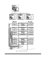
The state diagram which must be supported by a minimum capability device is shown in the following
figure.
Figure 5: Minimum capability device state diagram
01.07.1997
12
Implguid_public.doc STA Reutlingen
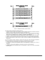
The 4 states are described in the following table:
State
Initialization
Pre-operational
Operational
Prepared
Description
This is the initial state after power on. In this state the initialization of the bus
interface and a module self test can be performed. There is no communication on
the bus during this state. The state is sub-divided in 3 phases:
• Reset Application:
Sets the power-on values for the manufacturer specific profile area and the
standardized device profile area, afterwards it enters the reset communication
phase.
• Reset Communication:
Sets the power on values for the communication profile, afterwards it enters the
init phase.
• Init:
sets the default COB-IDs for SDO, PDO and Emergency Objects
Afterwards the node automatically enters the Pre-operational state.
The node is now ready to communicate via the SDO channel. In this state the
node can be configured e.g. assigning PDO mapping and communication
parameters, set-up node guarding,
The node is fully operational. The node is synchronized if required and both SDO
and PDO channels are active.
The prepared state is used to disable a node via NMT Stop Remote Node service.
There is no SDO and PDO communication possible in this state. The node can be
set to operational state via NMT Start Remote Node service or to pre-operational
state via NMT Enter Pre-operational state service.
Table 2: State diagram description
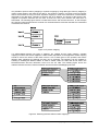
The NMT services which must be supported by a minimum capability device are formatted in a predefined structure. The structure is shown in the following figure:
Figure 6: NMT message format
107FRPPDQGVSHFLILHUFV
The command specifier is used to indicate the service. At the end of this chapter an overview of all
command specifiers is given.
1RGH,'
The node which has to be addressed by the service. If the Node-ID is 0 all nodes in the network are
addressed.
The COB-ID of the NMT service is always 0.
The following NMT services are used by a NMT master to force a NMT slave into the pre-defied states
described before.
The service primitives request and indication are used to describe the interaction between the
application and the NMT service element in the application layer as follows:
• a request is issued by the application to the application layer to request a service,
• an indication is issued by the application layer to the application to indicate that a service is
requested.
01.07.1997
13
Implguid_public.doc STA Reutlingen
The following table gives an overview of the used command specifiers. There are additional command
specifiers defined for CAL but they are not used by CANopen devices which support the state diagram
for minimal capability devices.
Command
Specifier
1
2
128
129
130
NMT service
NMT Start Remote Node
NMT Stop Remote Node
NMT Enter Pre-operational State
NMT Reset Node
NMT Reset Communication
Table 3: Command specifier overview
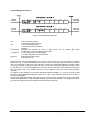
1076WDUW5HPRWH1RGH
The NMT Start Remote Node service forces the NMT Slave into the operational state. The protocol is
executed and formatted as follows
Figure 7: NMT Start Remote Node service
01.07.1997
14
Implguid_public.doc STA Reutlingen
107(QWHU3UHRSHUDWLRQDO6WDWH
The NMT Enter Pre-operational State service forces the NMT Slave into the Pre-operational state. The
protocol is executed and formatted as follows
Figure 8: NMT Enter Pre-operational State service
1076WRS5HPRWH1RGH
The NMT Stop Remote Node service forces the NMT Slave into the Prepared state. The protocol is
executed and formatted as follows
Figure 9 NMT Stop Remote Node service
01.07.1997
15
Implguid_public.doc STA Reutlingen
1075HVHW1RGH
The NMT Reset Node service forces the NMT Slave into the Initialization state. There it enters the
Reset Communication phase. The protocol is executed and formatted as follows
Figure 10: NMT Reset Node service
1075HVHW&RPPXQLFDWLRQ
The NMT Reset Communication service forces the NMT Slave into the Initialization state. There it
enters the Reset Application phase. The protocol is executed and formatted as follows
Figure 11: NMT Reset Communication service
01.07.1997
16
Implguid_public.doc STA Reutlingen
1RGH*XDUGLQJ
Node Guarding is used to detect remote errors in the network. With Node Guarding the NMT master
can watch its NMT slaves and the NMT slave can detect if the NMT master stops working. Node
guarding should be used if a slave is not polled on a regular time base by the master or if the slave
does not transmit PDOs regularly. If a remote error is detected the application should go in a save
state. The definition of a save state is strongly application dependent. Generally if the NMT master
detects a remote error it should force its NMT slaves into a save sate this can either be the state
Disconneted if the slaves are CAL compatible or the state Prepared if the slaves are minimum
capability devices. If a NMT slave detects a guarding error it should inform its application and the
application has to decide how to handle the error.
To perform the node guarding the NMT master checks the NMT slave state on a defined time base via
Remote Transmit Request (RTR) on the Node Guarding COB-ID. The NMT master compares the
received state to the state of its peer, if the comparison fails or if the state of the NMT slave could not
be retrieved the NMT master indicates that this is a remote error.
The Node guarding starts for the slave when the first remote transmit request for its guarding identifier
is received. The NMT master should request the NMT slaves with a time gap between the requests, it
should not request all slaves at once because the slaves response could be cause an overrun in the
masters receive message queue.
01.07.1997
17
Implguid_public.doc STA Reutlingen
Figure 12: Example Node Guarding
01.07.1997
18
Implguid_public.doc STA Reutlingen
6HUYLFH'DWD2EMHFW
The service data object uses the Multiplexed Domain Transfer Protocol /8/ to access the object
dictionary of each device. The type of data transferred may range from a simple boolean to a large file.
To meet the requirements of the different data types there are two transfer mechanisms introduced by
the Multiplexed Domain Transfer Protocol, these are:
• the expedited transfer is used for all data objects up to 4 bytes length,
• the segmented transfer is used for larger data objects.
The basic structure of a service data object is shown below.
Byte 0
Bytes 1 and 2
Byte 3
Bytes 4 to 7
,QLWLDWH
&RPPDQG
16 bit Index
8 bit Sub-Index
Domain
Command
Specifier
up to 4 Bytes Profile Data (expedited transfer)
RU
4 Bytes byte counter (segmented transfer)
up to 7 Bytes Profile Data (segmented transfer)
6HJPHQW
&RPPDQG
Byte 0
Bytes 1 to 7
Figure 13: Basic SDO Message Structure
The multiplexor is composed of a 16bit index and a 8 bit sub-index which together address a particular
data object in the object dictionary of a device. Note that always the client initiates the data transfer. In
a master-slave architecture the client would be represented by the master and the server would be
represented by the slave. The following figure shows the differences between the expedited transfer
and the segmented transfer of the multiplexed domain transfer protocol. The expressions in brackets
represents bits which are used by the protocol.
01.07.1997
19
Implguid_public.doc STA Reutlingen
Figure 14: Multiplexed Domain Transfer Protocol
The Service Channel provides the following services:
• Expedited Transfer of Data of size less than or equal to 4 bytes. This transfer mechanism needs the
transfer of 2 CAN messages only (Initiate Request, Initiate Response).
• Segmented Transfer of data whose size is greater than 4 bytes. All data objects with more than 4
bytes in size are transferred as a sequence of Segment Commands preceded by an Initiate
Command. This mechanism needs the exchange of at least 4 CAN messages.
• Transfer of a Data Identification Set (Index and Sub-Index as used in device profiles) with the data.
• Feedback of Error information with the Server Reply message:- with optional data set identification.
• Abort of Data transfer by either Client or Server, with error feedback and optional data set
identification.
The service primitives request, indication, response and confirm are used to describe the interaction
between the application and the CMS service element in the application layer as follows:
• a request is issued by the application to the application layer to request a service,
• an indication is issued by the application layer to the application to indicate that a service is
requested,
• a response is issued by the application to respond to a previous received indication,
• a confirm is issued by the application layer to the application to report on the result of a previously
issued request.
01.07.1997
20
Implguid_public.doc STA Reutlingen
'RZQORDG,QLWLDWLRQ([SHGLWHG3URWRFRO
Figure 15: Download Initiate and Response
ccs:
client command specifier
1: initiate download request
scs:
server command specifier
3: initiate download response
e: transfer type 0: segmented transfer
1: expedited transfer.
s: size
0: data set size is not indicated
1: data set size is indicated
n:
only valid if e=1 and s=1
if valid it contains the number of bytes which do not contain data
The CCS/SCS (Client Command Specifier/Server Command Specifier) field defines the meaning of the
telegram e.g. initiate upload/download and so on.
The e bit informs the server if the data transfer is expedited i.e. that the Initiate Request also contains
the relevant data.
A segmented download sequence is started by a client sending an ’Initiate Domain Download’ request
(ccs=1, e=0, s=0). If the server is willing to perform the request he should respond by transmitting an
acknowledgment telegram (scs=3).
01.07.1997
21
Implguid_public.doc STA Reutlingen
'RZQORDG6HJPHQW3URWRFRO
Figure 16: Downloading a Segment
ccs:
scs:
t:
n: valid bytes
c:completion
reserved:
x:
client command specifier
0: download segment request
server command specifier
1: download segment response
toggle bit
indicates the number of bytes in Data which do not contain data. Byte
numbers [8-n, 7] do not contain segment data.
0: more segments to be downloaded
1:no more segments to be downloaded
Reserved for further usage.
not used (set to 0)
Data segments are then transmitted from the client to the server with ccs=0 (’Domain Download
Segment’). The ’n’ field should indicate the number of bytes in the data segment that do not contain
data i.e. the number of filler bytes. This approach is used since the domain telegram is always a fixed
size (CAN maximum of 8 bytes) though not every byte of the remaining telegram bytes may be used
for real data. The ’c’ bit of the telegram sent from the client must be zero for all telegrams except the
last one. Setting the ’c’-bit indicates that the current telegram is the end of the current domain
operation.
In response to the reception of a ’Domain Download Segment’ telegram i.e. ccs=0, the server should
transmit an acknowledgement telegram where scs=1. The ’t’ field should be identical to the ’t’ field of
the received telegram.
During segmented data transfer, the toggle bit (t) is used to ensure packets which are re-transmitted
are not mis-interpreted i.e. helps maintain client/server packet synchronisation. The toggle bit is set to
0 for the first segment and have to alternate with successive segments.
01.07.1997
22
Implguid_public.doc STA Reutlingen
8SORDG,QLWLDWLRQ([SHGLWHG3URWRFRO
Figure 17: Upload Initiate and Response
ccs:
client command specifier
2: initiate upload request
scs:
server command specifier
2: initiate upload response
e: transfer type 0: segmented transfer
1: data contains the data to be transferred.
s: size
0: data set size is not indicated
1: data set size is indicated
n:
only valid if e=1 and s=1
if valid it contains the number of bytes which do not contain data
A domain upload happens in a similar manner to the domain download sequence described above.
The e bit informs the client if the data transfer is expedited i.e. that the Initiate Reply also contains the
relevant data:- no subsequent segments need to be downloaded.
01.07.1997
23
Implguid_public.doc STA Reutlingen
6HJPHQW8SORDG
Figure 18: Uploading a Segment
ccs:
scs:
t:
n: valid bytes
c:completion
client command specifier
3: upload segment request
server command specifier
0: upload segment response
Toggle Bit
indicates the number of bytes in seg-data which do not contain data. Byte
numbers [8-n, 7] do not contain segment data.
0: more segments to be uploaded
1:no more segments to be uploaded
For a segmented data transfer, the client transmits the ’Initiate Upload’ request with ccs=2and the
server should acknowledge the request by transmitting a response telegram with scs=2, e=0, s=1 and
n=number of bytes to upload.
The client then sends requests to the server for upload segments i.e. ccs=3, n=0. Note the toggle bit (t)
of the first segment request must be zero and this bit must alternate with successive segments.
The server should respond to a ’Upload Segment’ request (ccs=3) by transmitting a response telegram
where scs=0, c=0. ’t’ should be identical to the ’t’ field of the request and ’c’ should be zero except for
the last segment to be uploaded. The ’n’-field should indicate the number of bytes not containing data
in the data segment of the telegram.
01.07.1997
24
Implguid_public.doc STA Reutlingen
$ERUW7UDQVIHUIRUVHJPHQWHGWUDQVIHU
Figure 19: Domain Transfer Abort Protocol.
ccs:
appl-error-codes:
command specifier
4: abort domain transfer
specified for CANopen devices in their individual specifications
Both (non-expedited) upload and download domain services can be aborted be either client or server
by transmitting a packet of the segment protocol with the completion flag ’c’ set to one (see above).
However this merely conveys the fact that the transmission is over - it does not indicate an error
occurred since this is the normal transmission termination sequence. The error status, along with
optional Data Set Identification, can be reported in the data fields of the Abort Telegram (ccs = 4). In
case of the expedited transfer, the Abort Telegram would replace the Download or Upload Initiation
Response.
The appl-error-codes field is a 32 bit value composed of the following elements:
• Error-Class:
1 Octet
• Error-Code:
1 Octet
• Additional Code:
2 Octet
Byte:
4
Additional Code
6
Error-Code
7
Error-Class
8
The additional Code is also broken up into the following fields:
Bit:
15
Reserved
8
7
Global-Code
4
3
Specific-Code
0
The combination of the Error Class and the Error Code explain the error which has occurred. The
Additional Code is necessary with some error types to give further details of the fault.
01.07.1997
25
Implguid_public.doc STA Reutlingen
&RPPXQLFDWLRQ3URWRFRO(UURUV
Description
Toggle bit not alternated.
Error Class
5 Service Error
Multiplexor field or data field corrupted.
5 Service Error
Client/server command specifier not
valid
Time out value reached
5 Service Error
5 Service Error
Error Code
3 Parameter
Inconsistent
3 Parameter
Inconsistent
4 Illegal
Parameter
4 Illegal
Parameter
Additional Code
0
0
0
0
Table 4: Communication Protocol Errors
2EMHFW'LFWLRQDU\$FFHVV(UURUV
Description
Object does not exist in the object
dictionary
Attempt to read a write only Object.
Error Class
6 Access Error
Additional Code
0
6 Access Error
Error Code
2 Object nonexistent
1 Object access
unsupported
1 Object access
unsupported
4 Invalid address
Attempt to write a read only Object.
6 Access Error
The index value exceeds the limitations
of the object dictionary, the index is
reserved for further use, index values
from 00A0h-0FFFh and A000h-FFFFh
Access failed because of an hardware
error
Sub-index does not exist
6 Access Error
6 Hardware fault
0
6 Access Error
6 Access Error
9 Object attribute 11
inconsistent
7 Type conflict
10
Data type does not match, length of
service parameter does not match
Data type does not match, length of
service parameter to high
Data type does not match, length of
service parameter to low
Data cannot transferred to the
application or stored
Data cannot transferred to the
application or stored because of local
control
Data cannot transferred to the
application or stored because of the
present device state
Object dictionary dynamic generation
fails and no object dictionary is present
(e.g. object dictionary is generated from
file and generation fails because of an
file error)
Value range of parameter exceeded
6 Access Error
7 Type conflict
12
6 Access Error
7 Type conflict
13
8 Other Error
0
20
8 Other Error
0
21
8 Other Error
0
22
8 Other Error
0
23
6 Access Error
9 Object attribute
inconsistent
9 Object attribute
inconsistent
9 Object attribute
inconsistent
9 Object attribute
inconsistent
30
Value of parameter written too high
6 Access Error
Value of parameter written too low
6 Access Error
6 Access Error
Value range of sub-parameter exceeded 6 Access Error
01.07.1997
26
0
0
0
31
32
33
Implguid_public.doc STA Reutlingen
Value of sub-parameter written is too
6 Access Error
high
Value of sub-parameter written is too low 6 Access Error
Maximum value is less than minimum
value
Object cannot be mapped to the PDO
PDO length exceeded
General parameter incompatibility
reason
General internal incompatibility in the
device
6 Access Error
6 Access Error
6 Access Error
9 Object attribute
inconsistent
9 Object attribute
inconsistent
9 Object attribute
inconsistent
4 Invalid address
4 Invalid address
4 Invalid address
6 Access Error
4 Invalid address 44
6 Access Error
34
35
36
41
42
43
Table 5: Object Dictionary Access Errors
01.07.1997
27
Implguid_public.doc STA Reutlingen
3URFHVV'DWD2EMHFW
The Process Data is transmitted with the CMS Objects of the Stored Event Protocol according to the
CAL specification /7/. This protocol allows to use up to 8 bytes of a CAN message for process data.
The process data that have to be transmitted in the Process Data Objects(PDO) have to be defined in
the PDOMapping structure. The way how to transmit the data is described in the PDO communication
structure.
Figure 20: Stored Event Protocol
3'2&RPPXQLFDWLRQ3DUDPHWHU
With the PDO Communication Parameters the transmission behavior of a PDO is described. Therefore
a PDO Communication data type is defined. The PDOCommPar data type structured is as follows:
Index
0020H
Sub-Index
0H
1H
2H
3H
4H
Field in PDOMapping Record
number of mapped objects in PDO
COB-ID used by PDO
transmission type
inhibit time
CMS Priority Group
Data Type
Unsigned8
Unsigned32
Unsigned32
Unsigned32
Unsigned8
Table 6: PDO Communication Structure
01.07.1997
28
Implguid_public.doc STA Reutlingen
The sub-index 0 of the data type describes the number of entries. The maximal number of entries is 4
if the device supports the identifier distribution via DBT /12/. Otherwise it is 2 or 3 dependent on inhibit
time supported or not.
The COB-ID used by PDO is described by sub-index 1. In order to cater for 11-bit identifiers (CAN
2.0A) as well as for 29-bit identifiers (CAN 2.0B) the entry is defined as Unsigned32. The following
figure describes the format of the entry.
Unsigned32
MSB
LSB
bits
31
30
29
28-11
10-0
11-bit-ID
0/1
0/1
0
000000000000000000
11-bit-Identifier
29-bit-ID
0/1
0/1
1
29-bit-Identifier
Figure 21: Structure of PDO COB-ID entry
bit number
value
description
31
0
PDO valid
1
PDO not valid
0
RTR allowed on this PDO
1
no RTR allowed on this PDO
0
11-bit-Identifier (CAN 2.0A)
1
29-bit-Identifier (CAN 2.0B)
0
if bit 29=0
X
if bit 29=1: bits 28-11 of 29-bit-COB-ID
X
bits 10-0 of COB-ID
30
29
28-11
10-0
Table 7: Description of PDO COB-ID entry
The PDO valid/not valid bit is used to enable or disable a PDO. The bit determines which PDO is used
in the operational state. The Bits 29 and 30 may be static , e.g. due to hardware restrictions. In that
case no error is signaled on the attempt to change them.
The sub-index 2 describes the transmission character of the PDO. The following table describes the
usage of this entry.
Transmission
Type
0
1-240
241-251
252
253
254
255
PDO
transmission
cyclic
acyclic
X
X
reserved
sync.
X
X
async.
X
X
X
X
RTR only
X
X
Table 8. PDO transmission types
01.07.1997
29
Implguid_public.doc STA Reutlingen
3'20DSSLQJ
With the PDO Mapping the structure of a PDO is described. Therefore a PDO Mapping data type is
defined. The PDOMapping data type is structured as follows:
Index
0021H
::::::
Sub-Index
0H
1H
2H
::::::
40H
Field in PDOMapping Record
number of mapped objects in PDO
1st object to be mapped
2nd object to be mapped
::::::::
64th object to be mapped
Data Type
Unsigned8
Unsigned32
Unsigned32
::::::
Unsigned32
Table 9: PDO Mapping Structure
The Sub-Index 0 of the data type describes the number of entries. The maximal number of entries is
64 if the granularity is 1. Granularity is defined as minimal object length in bits which can be mapped.
Most of the existing devices support a granularity of 8 bits, which means that the objects which can be
mapped are at least 1 byte and the maximal number of entries is 8.
The entries from sub-index 1 to the number of maximal entries is shown in the following figure:
Byte:
MSB
index (16 bit)
LSB
object length (8 bit)
sub-index (8bit)
Figure 22: PDO Mapping entry
The index field in the PDO Mapping entry includes the index of the object which is mapped. If a record
or a array is mapped the sub-index field includes the sub-index of the object. The object length field
describes the length in bits of the object which is mapped. The following figure shows the relations
between the objects mapped in a PDO and the object dictionary.
2EMHFW'LFWLRQDU\
,QGH[
6XE
1DPH
7\SH
device type
error register
::::
1st transmit PDO communication
parameter
number of entries
COB-ID used by PDO
transmission type
inhibit time
CMS priority group
::::
1st transmit PDO mapping parameter
number of mapped objects in PDO
Unsigned32
Unsigned8
::::
PDOComPar
,QGH[
1000h
1001h
::::
1800h
0
1
2
3
4
::::
1A00h
0
1
2
3
::::
6000h
0
1
6400h
0
1
st
1 object to be mapped
2nd object to be mapped
3rd object to be mapped
::::
digital input
number of digital iputs
read 8 inputs 1H-8H
analog input
number of analogue inputs
input 1H
Unsigned8
Unsigned32
Unsigned8
Unsigned16
Unsigned8
::::
PDOMapping
Unsigned8
Unsigned32
Unsigned32
Unsigned32
::::
Unsigned8
Unsigned8
3'2
Byte: 0
6000h
,QGH[
6000h
6400h
1001h
1
6400h
3
1001h
6XE
2EMHFW
,QGH[
/HQ
1
1
0
8
16
8
3'20DSSLQJ6WUXFWXUH
Unsigned8
Integer16
Figure 23: Relations between object dictionary and PDO
01.07.1997
30
Implguid_public.doc STA Reutlingen
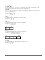
It is possible to perform dummy mapping or symbolic mapping by using data types. Dummy mapping is
used to mask entries in the PDO for the device. This feature is useful if one PDO is used to transmit
data to several devices using one PDO. Symbolic mapping is useful if the data which is transmitted is
described by the data itself. Therefore a structure has to be defined. The entries of the structure are
mapped as symbolic elements into the PDO. At least one entry must describe the data which is
transmitted. The following figure shows a multichannel device and the PDO structure, In this example
the channel number determines the channel of a multichannel device and the data which is transmitted
is related to this channel.
Figure 24: Symbolic mapping
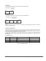
It is differentiated between two types of mapping, the variable and the static mapping. Variable
mapping is useful if the entries mapped in a PDO variate, dependent on the application. Static mapping
should be used if the entries of the PDO is fixed. A mix of both types is also possible, that means
different static mappings are defined and they can be switched. The switching can be realized by
enabling or disabling the different PDOs. In order to enable a PDO, the PDO has be set valid in the
PDOCommParam structure otherwise it has to be set not valid. The following figure shows the
relations between the PDO, PDOCommParam structure and the PDOMapping structure.
Figure 25: Switching between different static mappings
01.07.1997
31
Implguid_public.doc STA Reutlingen
1HWZRUN6\QFKURQL]DWLRQ
Besides the cyclic exchange of data many real time applications demand synchronization between
different bus nodes. I.e. axis of a kinematics have to be synchronized or I/O modules have to set
outputs or read inputs simultaneously like a PLC. Synchronized drives expect commanded positions
and send actual positions in pre-defined time windows. CANopen meets these requirements by
introducing an optional synchronization telegram with a high priority, which divides the time axis in
equidistant communication cycles (see Figure 26:CANopen Bus Timing). The synch-message does not
contain data and can be used as an interrupt by I/O modules to then set outputs or read inputs.
Intelligent devices like drives can synchronize e.g. using the PLL method. In the report window right
after the synchronization telegram the drives send their actual and the I/O modules send their input
values. Afterwards, in the command window, the commands and the output values are transmitted,
which are then set valid at the next synch-signal. As the report window directly follows on the synchsignal it can be hit even by simple components without using timers. Bandwidth not used inside the
windows and the time between the command window and the synch telegram is available for lowpriority SDO messages.
As the synchronization telegrams are optional, it is also possible to operate CANopen networks in
totally asynchronous manner if desired. However, bus traffic and processor loading are much more
predictable if bus synchronization is used.
For applications that require optimal synchronization (the synch-message may jitters slightly due to bus
traffic at the synch transmission time), an optional high resolution synchronization method has been
specified which uses time stamping of synch messages. This enhanced synchronization is especially
useful for low speed networks with hard synchronization requirements. However, it has been shown
that the standard synchronization method perfectly good at operating robot kinematics.
Synch
Telegram
Synch
Telegram
Communication Cycle
Report
Window
Command
Window
asynchronous messages
inputs and actuals
read at the
synch telegram
commands (i.e. outputs, drive commands)
are executed at the
next synch telegram
Figure 26:CANopen Bus Timing
01.07.1997
32
Implguid_public.doc STA Reutlingen
%RRW8S
The CANopen boot-up approach caters both for simple and sophisticated devices by defining a
mandatory minimal boot-up procedure that can be optionally enhanced if additional features are
required. The full version is equivalent to the standard CAL boot-up, ensuring that the whole range of
CAL features is accessible. However, the minimal version already covers a wide range of applications.
The boot-up procedure assumes that by default the peripheral devices do not have to know what kind
of application they are operating in. The network configuration takes place at one unit which can be the
network management (NMT) master or a separate configuration tool called configuration master which
remotely controls the NMT master. At the boot-up this master device can download the configuration
data via service data objects to the configuration slaves. If the slaves are capable of storing this
information, this only has to take place if the configuration changes.
CANopen defines a set of default identifiers which are derived from a node-ID, thus providing access
via an SDO to the object dictionary and real-time master/slave communication via PDOs without any
specific parameterisation. Of course this default identifier distribution can be modified either by
changing the appropriate parameters in the object dictionary (SDO access), or by employing CAL DBT
services, if present. However, applications that comprise one device that controls all others can
operate sufficiently well with the default settings.
The minimal boot-up covers only two states: pre-operational and operational (see Figure 5: Minimum
capability device state diagram). After power-on, a device is pre-operational, thus giving read and write
access to its object dictionary as the service communication is established using default identifiers.
The devices can now be configured (including identifier distribution via object dictionary access) if the
default settings are not satisfactory. With the standard CAL “start_remote_node” command then the
devices are switched into “operational” in order to start PDO communication. PDO transmission can be
stopped altogether if requested by switching the device back into pre-operational. By using the CAL
command “disconnect_remote_node” all communication parameters are reset, default values (e.g.
preset identifiers) are valid again. All (NMT-) commands needed for this minimal boot-up use identifier
0 and are distinguished with the command specifier (cs) in the first data byte.
More sophisticated devices will support the full (CAL) boot-up including DBT services which is started
with a “disconnect” command, as all devices enter “pre-operational” after power-on. It is possible to
have all combinations of devices in the same network, as the full boot-up can be performed separately
with each device supporting it whilst the minimal boot-up is performed with the other devices. If the
network master only supports minimal boot-up, all slaves behave like minimal slaves.
This boot-up concept ensures that very lean implementations are possible as all parameterisation
(including most of the network configuration) can be done via one single CMS service, the multiplexeddomain protocol of the service data object. If the default settings are sufficient or if the devices are
capable of storing their configuration data, the boot-up is reduced to one single two-byte message:
“start all nodes”.
For additional information see also section 16.
01.07.1997
33
Implguid_public.doc STA Reutlingen
(PHUJHQF\0HVVDJH8VDJH
The Emergency message is used to notify an internal device error to the network. For instance, the
voltage of the device reaches a critical limit whereas the network interface is still in good working
conditions. For the notification of this type of errors an emergency telegram have to be generated. The
emergency message have to be sent only once per error event. Afterwards the error has to be stored
in the object 1003h pre-defined error field. In this object the latest error is stored at sub-index 1. The
numbers of errors which occurred are stored in sub-index 0. The error list can be flushed by writing 0
to the sub-index 0. The following table gives an overview of the emergency error codes defined in the
Communication Profile DS301 /2/.
(UURU&RGHKH[
00xx
10xx
20xx
21xx
22xx
23xx
30xx
31xx
32xx
33xx
40xx
41xx
42xx
50xx
60xx
61xx
62xx
63xx
70xx
80xx
81xx
90xx
F0xx
FFxx
0HDQLQJ
No Error
Generic Error
Current
Current, device input side
Current inside the device
Current, device output side
Voltage
Mains Voltage
Voltage inside the device
Output Voltage
Temperature
Ambient Temperature
Device Temperature
Device Hardware
Device Software
Internal Software
User Software
Data Set
Additional Modules
Monitoring
Communication
External Error
Additional Functions
Device specific
Table 10: Emergency Error Codes
The emergency telegram is formatted as follows.
Byte 0
Byte 1
Emergency Error
Code
Byte 2
Byte 3
Error
Register
Byte 4
Byte 5
Byte 6
Byte 7
Manufacturer specific Error Field
(Object
1001H)
Figure 27: Mapping Emergency Message
01.07.1997
34
Implguid_public.doc STA Reutlingen
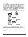
+DUGZDUH$VSHFWV&$1FRQWUROOHUV0LFURFRQWUROOHU
The following chapter gives an overview of general CAN hardware aspects in conjunction with
CANopen.
)XOO&$1
Full CAN devices contain additional hardware to provide a message "server" that automatically
receives and transmits CAN messages without interrupting the associated microcontroller. Full CAN
devices carry out extensive acceptance filtering on incoming messages, service simultaneous
requests, and generally reduce the load on the microcontroller. Full CAN devices also have extended
buffering capabilities. Often Full CAN controllers are equipped with additional hardware witch can be
used by the application e.g. I/O Ports. A good combination for a CANopen slave node is a Full CAN
controller in combination with an 8 bit microcontroller where the Full CAN controller handles the
communication and the microcontroller the application.
%DVLF&$1
In Basic CAN configurations there is a tight link between the CAN controller and the associated
microcontroller. The microcontroller, which will have other system related functions to administer, will
be interrupted to deal with every CAN message. For example, an interrupt is generated to check the
identifier of every received message to determine if the message is relevant to the node. Although the
interrupts may be serviced quickly, the other system loads on the microcontroller may limit the number
of messages that can be processed in a given time. A Basic CAN controller is suitable for a CANopen
Master implementation, because a master must handle all CAN messages anyway which are on the
bus and does not use the advantages of a Full CAN controller.
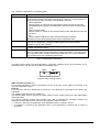
+DUGZDUH6HWXS
In order to set-up a CAN node the node-ID and the baudrate must be configured before the node is
accessed via the network. The most suitable solution to set-up the node-ID and the baudrate is to use
DIP-switches. If the CAN node is switched on or reset the application first reads the node-ID and the
baudrate from the DIP switches. Another possibility is to create two objects in the manufacturer
specific profile area in the object dictionary and store the data in the non-volatile memory. Then the
node has to be configured first in a separate network. After that the node can be integrated into the
target network.
01.07.1997
35
Implguid_public.doc STA Reutlingen
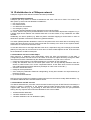
,'GLVWULEXWLRQLQD&$1RSHQQHWZRUN
CANopen supports three different identifier allocation possibilities:
'HIDXOW,GHQWLILHU'LVWULEXWLRQ
CANopen (DS 301) defines a default ID distribution that each node has to follow. This means, that
after power up each node has identifiers available for:
• two receive PDOs
• two transmit PDOs
• one SDO with two identifiers
• one emergency object
• one node guarding identifier (simply derived from the node-ID-offset)
Of course, a device only has to provide identifiers for the communication objects that it supports. E.g. if
a simple input device features one transmit PDO and no receive PDOs, it only establishes one PDO
identifier.
Additionally, the device profiles (e.g. DSP-401) define a default mapping for these PDOs in order to
allow basic operation of the device without any parameterisation.
This static (default) identifier distribution caters for all systems with one master device controlling many
slaves (the Slave devices can only communicate with the master), but it does not suit systems where
slaves have to communicate with each other.
In case the slaves are to exchange data with each other, it depends if they just exchange process data
(PDOs) or if they want to communicate to each other via Service Data Objects as well. In the first case
the ID distribution via SDO is adequate:
,'GLVWULEXWLRQYLD6HUYLFH'DWD2EMHFW
After power-up, a CANopen node automatically enters the state SUHRSHUDWLRQDO. In this state, a
(configuration) master has full access to all entries of the device’s object dictionary through the SDO
channel that has been established by the default ID distribution. This path can be used to:
• modify the PDO mapping, if the default mapping is not suitable for the application,
• modify the Identifiers used for the PDOs (this means one can dynamically distribute PDO ID’s
similar to a DBT master, but in a less complicated fashion, as the Slave does not have to transmit
many DBT parameters already defined by CANopen in order to ask for the ID’s.),
• activate or deactivate PDOs,
• modify all device parameters,
• even modify the parameters related to nodeguarding, as they are included in the object dictionary of
the device as well,
• up- and download software.
DBT services are required in CANopen systems when there is the need to modify SDO identifiers, e.g.
to establish additional SDO channels between slaves.
,'GLVWULEXWLRQYLD'%7VHUYLFHV
This follows standard CAL procedure, where the NMT master may kick off DBT Slave functionality in a
device by setting a parameter in the Prepare_Remote_Node Request during boot-up. CANopen
supports DBT services (e.g. by permitting to start DBT services directly from the pre-operational
status), but only requires them when SDO identifiers have to be modified.
•
•
•
default identifier distribution
Identifier distribution via SDO
Identifier distribution via CAL-distribution (DBT)
01.07.1997
36
Implguid_public.doc STA Reutlingen
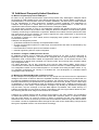
&$1RSHQ'HYLFH3URILOHV
CANopen Device Profiles are used to describe a class of devices. The following CANopen device
profile specifications are available:
Title
Device Profile for I/O Modules
CANopen Device Profile for Drives and
Motion Controller
CANopen Device Profile for Encoders
Revision
1.3
1.0
CiA Draft Standard Proposal
401
402
1.0
406
Table 11: Device profiles
The following CANopen device profile specifications are in preparation:
Title
CiA Work Draft
CANopen Device Profile for Measuring Devices and 404
Closed Loop Controllers
CANopen Device Profile for Programmable Devices
405
CANopen Device Profile for Public Transport
407
Table 12: Device profiles in preparation
01.07.1997
37
Implguid_public.doc STA Reutlingen
$GGLWLRQDO)UHTXHQWO\$VNHG4XHVWLRQV
4:KDWLVWKHSKLORVRSK\EHKLQG&$1RSHQ"
$ CAN is a very powerful communication system that provides many advantages. CANopen makes
the benefits of CAN available for the user without bothering him with complex details concerning e.g.
parameterisation of communication services, identifier distribution, real time tuning of CAN networks.
For the manufacturer of CAN components, CANopen provides significant cost advantages as
CANopen was designed to enable lean but powerful protocol implementations. A Slave can be
implemented with less than 4kByte of ROM and less than 100 Bytes of RAM.
The profile family provides an easy to use application interface that includes access to all device
parameters and functions via procedure calls. CANopen allows the realization of multi-vendor systems
containing a wide range of automation components. Besides the excellent real time performance both
with event driven and cyclic behavior, the system supports the quick transmission of asynchronous
data like device parameters or programs.
As CANopen is based on a CAL subset, devices employing these profiles can operate in a CAL
environment if desired.
CANopen was designed to provide
• good balance between functionality and implementation effort,
• an open communication system for a wide range of manufacturers and users not dominated by only
a single company,
• less maintenance costs for protocol and software versions,
• reduced engineering effort for system integration.
4+RZGR,FRQILJXUHD&$1RSHQVODYHGHYLFH"
$ CANopen assumes that by default the peripheral devices do not have to know what kind of
application they are operating in. The devices are equipped with an object dictionary containing all
parameters, both communication related and application related ones. For all relevant entries in this
object dictionary a default value is defined in the device profile, thus ensuring basic operation without
any configuration need.
The object dictionary can be fully accessed via the Service Data Object (SDO), which forms a
communication channel that is established between the device and the so called configuration master.
The configuration master can be located anywhere: in a controller unit hosting the NMT master, or e.g.
in a separate configuration tool running on a standard PC. The development of a Windows based
configuration tool is under way.
40LQLPDODQG([WHQGHG%RRW8SKRZGRHVLWZRUN"
$ The CANopen boot-up approach caters both for very simple low-cost devices and for sophisticated
intelligent CAN nodes. It allows to follow an expedited mandatory minimal boot-up procedure that can
be enhanced if additional features are required. However, the minimal version, where the devices are
basically switched from pre-operational into operational mode and back, already covers a wide range
of applications. In the pre-operational mode, the SDOs are already active, enabling full access to the
object dictionary of the device. Synchronisation messages may already be transmitted, lifeguarding
may be active, only the exchange of Process Data Objects is prohibited. This "small" boot-up is a
subset if the extended (or "full") boot-up, which is equivalent to the boot-up procedure defined by CAL,
thus ensuring that the whole range of CAL features is accessible.
CANopen very carefully assures that all versions work together in the same network. Any combination
of master and slaves is possible, e.g. "full scale" master with "minimum" slaves, or "minimum" master
with "full scale" slaves. Of course a mixture of slaves is supported as well. The network master
determines which version of the boot-up is executed, as he takes his slaves through the state machine.
The master can take a sophisticated Slave through the full scale version whilst taking a simple device
through the expedited method. The slaves follow accordingly.
01.07.1997
38
Implguid_public.doc STA Reutlingen
4:KDWNLQGRIERRWXSVKRXOG,VXSSRUWRQD&$1RSHQ6ODYH"
$Thisdepends on the market segment your device is aimed at. If it is aimed to operate in CANopen
networks, the required boot-up depends on the functionality that you want to support (see above). If it
is aimed to operate in standard CAL networks as well, you have to support the full boot-up (with or
without DBT).
4:KDWNLQGRIERRWXSVKRXOG,VXSSRUWRQD&$1RSHQPDVWHU"
$ As the master determines how the boot-up is performed, your choice is related to the features that
you want to support. If the CANopen specific features are sufficient, a small boot-up version will do.
CANopen ensures that you can boot all kind of (CANopen) slaves.
48VHRI6/,2V"
$ A SLIO cannot be used as a minimum CANopen slave node. A SLIO cannot provide an object
dictionary thus the requirements for a CANopen node are supported, furthermore it cannot be
controlled by NMT services.
4+RZLVWKH3'26'2DOORFDWLRQIURPWKHPDVWHU¶VSRLQWRIYLHZ"
$A master must know all its associated slaves node IDs and must be able to derive the predefined
CAN identifiers from the slaves node IDs. If the master does not communicate via the predefined
master slave connection set it must store the identifiers in its non volatile memory.
4+RZGR,FRQILJXUHDPDVWHUGHYLFH"
$If a master device must be configurable it must provide an object dictionary. Then the master can
be configured like a CANopen slave node via its object dictionary.
01.07.1997
39
Implguid_public.doc STA Reutlingen