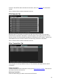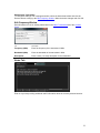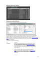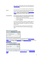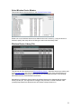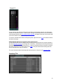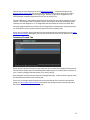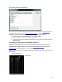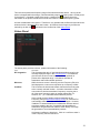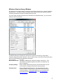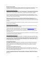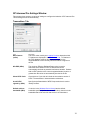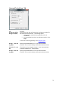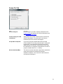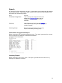
1
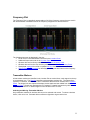
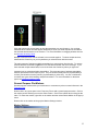
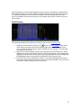
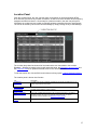
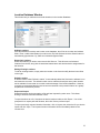
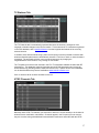
Version 1.0.6
Table of Contents
Table of Contents ............................................................................................................ 2
Introduction ..................................................................................................................... 3
What is Intermodulation Distortion? ........................................................................... 3
RF-intermod PROTM does it all with One-Click ......................................................... 3
RF-intermod PROTM Configurations .......................................................................... 3
Overview ......................................................................................................................... 4
Using RF Intermod Pro for the First Time .................................................................. 5
RF Intermod Pro Main Screen ........................................................................................ 8
Main Menu and Toolbar .................................................................................................. 9
Frequency Plot............................................................................................................... 11
Transmitter Markers .................................................................................................. 11
General Purpose Plot Markers................................................................................... 12
Plot Zooming ............................................................................................................. 13
Plot Key ..................................................................................................................... 14
Location Panel ............................................................................................................... 15
Location Database Window ...................................................................................... 16
TV Stations Tab ........................................................................................................ 17
NTSC Channels Tab.................................................................................................. 17
DTV Channels Tab.................................................................................................... 18
Other Transmitters Tab ............................................................................................. 18
Notes Tab .................................................................................................................. 19
Wireless Inventory Panel .............................................................................................. 20
Wireless Inventory Window...................................................................................... 20
Wireless Device Library Tab .................................................................................... 22
Inventory Tab ............................................................................................................ 23
Inventory Groups Tab ............................................................................................... 24
Auto-Assign Results Window ................................................................................... 25
Overriding Frequency Plot Candidate Selection ....................................................... 25
Status Panel ................................................................................................................... 26
Wireless Device Library Window ................................................................................. 27
Edit Device Preset Window ...................................................................................... 29
RF Intermod Pro Settings Window ............................................................................... 30
Transmitters Tab ....................................................................................................... 30
Intermod Calculations Tab ........................................................................................ 31
Sweep Plot Tab.......................................................................................................... 32
Reports .......................................................................................................................... 33
Transmitter Assignments Report ............................................................................... 33
Inventory Report ....................................................................................................... 33
Inventory Groups Report ........................................................................................... 34
Exporting Transmitter Assignments ............................................................................. 35
Importing Sweep Data ................................................................................................... 35
Display Data from Invisible Waves X Software ........................................................... 36
Exporting Sweep Plots from Invisible Waves X Software ....................................... 36
Real-time Updates from Invisible Waves X Software .............................................. 36
2
Introduction
TM
The PC-based RF-intermod PRO refines and simplifies the process of identifying
intermodulation distortion (IMD) frequencies in a given RF spectrum and is designed for
professional audio wireless microphone users, AV installers of wireless devices, frequency
coordinators, and broadcasters.
What is Intermodulation Distortion?
Intermodulation distortion is created when two or more transmission frequencies mix together and
form new additional signals. Sometimes referred to as ‘spurious emissions’, these newly created
frequencies are both harmonic frequencies and also the sum & difference of the original
frequency. And, these newly generated frequencies may be strong enough to cause interference
to any transmitter that tries to occupy the same RF-spurious emissions space.
RF-intermod PROTM does it all with One-Click
TM
The new RF-intermod PRO graphically displays on the screen the predicted locations of these
intermod components and assists in the frequency coordination process. Based on the user’s
selection of transmitter models from a model selection list, the software will advise the user on the
best selection of transmitters/frequencies. Additionally, based on zip code entry, the software
automatically defines and identifies unusable RF spectrum spaced around local DTV channels
and other local interference. What makes this software standout over other intermod prediction
software is the intuitive ease-of-use; ‘One Click’ calculations, Click, Drag & Place, spectral
graphical representation, customizable TX inventory profiles, DTV blocks, and stable reliability.
TM
One of the more powerful and unique functions of the RF-intermod PRO is the RF Risk
tm
Assessment feature. This feature evaluates the potential interference conditions based on the
user’s tolerance level and selects, assigns, and performs the whole frequency coordination
process for the user. It’s a ‘one button push’ process, based off of the user’s wireless inventory
which greatly speeds up frequency coordination with added accuracy. Naturally the user can
override and/or modify the computers automatic suggestions by manually inserting transmitters’
right onto the graphic RF spectral display, and thereby still avoid RF interference hazards.
tm
Another unique and power feature is the weighted RF Density Congestion Scale which displays
the predicted severity of the local RF environment. One of the many advantages of this feature is
the ability to gauge and predict the RF severity and then decide on the best transmitter models to
use in the environment or to supplement with wired devices in extreme cases.
RF-intermod PROTM Configurations
TM
The RF-intermod PRO is available as a standalone PC-based software product or as a plug-in
TM
TM
option for the Invisible Waves RF Command Center. As a plug-in, the RF-intermod PRO
works in conjunction with the RF Command Center’s Frequency Coordinator, scanning the local
RF environment in real-time, identifying open and usable RF spectrum, and at the same time
TM
performing real-world intermod calculations. When the RF-intermod PRO is used as a plug-in
with the RF Command Center, the combination becomes the most power RF coordination
solution available.
3
Overview
RF Intermod Pro is a powerful, graphical-based interactive tool to assist in coordinating frequency
assignments for wireless transmitters. Frequency assignment takes into consideration the
rd
th
placement of existing transmitters as well as the 3 and 5 order intermodulation interference
caused by the placement of transmitters as they interact with each other and with selected
wireless devices.
The following features are provided to simplify the setup of frequency coordination:
Location Database
The user can enter information on any number of geographical locations. Information includes:
• A unique name identifying the location.
• The physical address (street, city, state, zip code, longitude & latitude) of location.
• Local NTSC and DTV stations that may interfere with wireless transmitters (see FCC
Transmitter Database, below).
• Additional (non-TV) frequencies at the location.
• An optional spectral frequency plot for the location.
• Wireless transmitters assigned by the user at that location.
• Written notes on the location.
FCC Transmitter Database
RF Intermod Pro includes a database of over 25,000 NTSC and DTV transmitters in the United
states. Enter in a zip-code (or enter longitude and latitude directly if you have it), and RF
Intermod Pro will automatically determine which local stations have the potential to interfere with
your wireless devices. You can also select NTSC and DTV channels manually if you desire.
Wireless Device Library
Also included is a library of commonly available wireless transmitter devices from a variety of
different manufacturers. You can edit the database to add your own wireless devices as
required.
Wireless Inventory and Inventory Groups
Using the devices from the Wireless Device Library, the user can create their own custom device
inventory. Inventory can also be assigned to groups that define different venues, location or
application types. Inventory groups allow automatic assignment of multiple inventory items with
one or two clicks.
Interactive Frequency Plot
A fully interactive frequency plot lets you graphically view all of the frequencies that come into
play as you coordinate you wireless device assignments.
Select local NTSC and DTV stations from the Location Panel and watch them immediately
appear on the plot, along with any intermodulation distortion they may cause (note: DTV stations
are not included in intermodulation calculations).
Drag wireless devices from the Wireless Inventory Panel onto the plot and move them around,
selecting from a graphical representation of candidate frequencies that are free of interference for
that device.
4
Using RF Intermod Pro for the First Time
Here are some quick steps to getting you started using RF Intermod Pro:
1. Install and run RF Intermod Pro. This is how the main screen should look:
2. In the Location Panel, click the TV Stations tab. Then click Edit Locations to bring-up the
Location Database Window.
5
3. Enter in your zip code and click on Search. If you entered a valid U.S. zip code, the City,
State and Latitude/Longitude fields will be filled-in automatically.
4. Now, click OK, and then click Yes when prompted for auto-selecting TV stations. Your
Location Panel should now look something like this:
As you can see, the list has been filled with information on TV stations within a certain radius of
your location. Based on the RF Intermod Pro’s internal risk assessment calculations, some of the
stations include a check mark in the Channel column indicating that a channel is strong enough to
potentially interfere with wireless transmitters you might assign. Feel free to go through the list
and check/uncheck stations as you feel appropriate.
You will also notice that the selected TV stations now appear in the Frequency Plot.
6
5. Now, click on any item in the Wireless Devices Library list and drag it onto the frequency plot.
While you are dragging, you will notice that the frequency plot displays optimum candidate
frequencies where the device can be placed and avoid interference.
6. You can also highlight any item(s) in the Wireless Devices Library and then click the “Assign”
button. The RF Intermod Pro will place the devices into the frequency plot at the optimum
location based on best intermodulation calculations and best spacing from other transmitters.
You can repeatedly click on the “Assign” button over and over to continue to place the
devices into the frequency plot at the optimum locations.
7. Once assignments are complete, you can create a report of the assigned transmitters by
selecting (from the main menu) FilesàReportsàTransmitter Assignments. Click save when
prompted with a file browser. The transmitter assignment report will appear in an editor.
Now that you’ve assigned transmitters directly from the Wireless Device Library, try creating
inventories and inventory groups to make managing your RF coordination even easier.
7
RF Intermod Pro Main Screen
Below is how the RF Intermod Pro main screen may typically appear while in full usage, showing
all panels and windows.
The main screen includes the following elements:
Item
Description
Main Menu/Toolbar
Quick access to features and functions.
Frequency Plot
Graphical representation of selected TV channels and
stations, selected wireless transmitters and calculated
intermodulation products.
Plot Key
Legend for identifying symbols found on the
Frequency Plot.
Location Panel
Setup panel for selecting TV channels/stations and
additional frequencies, in a given location, that are
used in the intermodulation calculations.
Wireless Inventory
Panel
Provides access to the wireless device library, user
inventory and inventory groups.
Status Panel
Shows RF Congestion, mouse cursor position and RF
conflict list.
8
Main Menu and Toolbar
The following lists show all main menu and toolbar functions.
File Menu
Menu Item
Button
Description
Saves all user data, including location and inventory information.
Save Data
Reports
*
Creates selected report. Choose from:
Transmitter Assignments Report (*button available)
Inventory Report
Inventory Groups Report
Export
--
Export selected data. Choose from:
Transmitter Assignments
Import
--
Import selected data. Choose from:
Sweep Data
Settings
Exit
Brings up the RF Intermod Pro Settings window.
--
Exits RF Intermod Pro
Plot Menu
Menu Item
Show Key
Button
--
Include Sweep Data
Clear Sweep Data
Description
Show/Hide the Plot Key window.
Include/exclude sweep data in frequency plot.
--
Clears current sweep data buffer.
Accept IWx Sweep
Data
Display real-time updated spectral sweep data from Invisible
Waves software (requires Invisible Waves version 1.1.0 or
above). (See Real-time Updates from Invisible Waves.)
Zoom Mode
Enable/disable frequency plot zoom mode (see Frequency Plot.)
Plot Menu
Menu Item
Button
Description
Location Panel
--
Show/Hide the Location Panel
Inventory Panel
--
Show/Hide the Wireless Inventory Panel.
Status Panel
--
Show/Hide the Status Panel.
Tools Menu
Menu Item
Wireless Device
Library
Button
--
Description
Brings-up the Wireless Device Library Window.
9
Help Menu
Menu Item
Button
Description
Contents
--
Shows the Help Table of Contents window.
Search
--
Shows the Help Topic Search window.
Index
--
Shows the Help Topic Index window.
About RF Intermod
Pro
Brings-up RF Intermod Pro software version information.
Click this button to activate context help and then click on the
item you would like help with.
10
Frequency Plot
The Frequency Plot is a graphical representation of all of the frequency sources that are used in
the intermodulation calculations and in the frequency assignment of wireless devices.
The following items can be displayed in the plot:
• NTSC and DTV channels/stations selected in the Location Panel.
• Additional frequencies enter in the Location Panel.
• Wireless devices from library added from the Wireless Inventory Panel.
• Wireless devices from the user inventory added from the Wireless Inventory Panel.
• Sweep data imported from a file or updated real-time from Invisible Waves software.
• General Purpose Plot markers for identifying or calling-out other items on the frequency
plot.
Transmitter Markers
All transmitter markers are identified in the Location Plot as vertical lines, each capped on the top
by a transmitter icon. The Plot Key identifies each transmitter markers icon. The shorter lines
represent TV stations, channels and “other” transmitters that have been selected in the Location
Panel. The longer lines are wireless transmitter devices that have been added from the Wireless
Inventory Panel. Please note: Because the FCC assigns TV station frequencies by their ‘start’
frequency, the lines for TV stations appear on the left side of the TV block.
Selecting and Moving Transmitter Markers
Only transmitter markers for wireless devices can be selected and moved. To select a wireless
device, click on its icon. Selected devices will have a light blue ring around its icon.
11
Click and hold the left mouse button to drag the transmitter to a new frequency. As you drag,
additional white marker lines will appear temporarily to show you which frequencies are safe for
the selected wireless device to be moved to. For more information on dragging wireless devices
see Wireless Inventory Panel.
Multiple wireless devices can be selected, but not moved together. To select multiple devices,
hold down the Control key on your keyboard as you select devices with the mouse.
The main purpose of selecting multiple transmitters is to remove them from the plot. To remove
selected wireless transmitters, right-click on a selected transmitter and select Unassign. If you
have selected multiple transmitters, be sure hold down the Control key when you right-click.
Important note on selecting wireless transmitters: There are two types of wireless transmitters
devices represented in the Frequency Plot. They are wireless library devices (represented by a
red line), and wireless inventory devices (represented by a yellow line). You are not allowed to
mix these two types while selecting multiple transmitters. For more information on these two
types, see Wireless Inventory Panel.
General Purpose Plot Markers
General purpose markers allow you to add notes or comments to point out certain features in the
Frequency Plot.
Double click in any open space in the Frequency Plot to add a general purpose marker. Click on
the marker pointer and drag to move the entire marker. Click on the marker label to drag just the
label. To delete the marker, right-click on the marker and then select Delete Marker in the pop-up
menu.
Double click on the marker to bring-up the Marker Settings window.
Marker Settings
12
This window lets you customize the appearance of a plot marker. By default, the markers label
will show the frequency value at the marker’s locations, and will change as the marker is moved.
To customize the label text, check the Custom label box and enter the desired marker label.
Click the Set Marker Color button to bring-up a color selector from which to choose a new color
for the marker.
Plot Zooming
The following methods are provided form zooming in and out in the Frequency Plot:
button in the main toolbar. When in this
1. Enable plot zoom mode by clicking on the
mode, the mouse cursor turns into a magnifying glass while over the Frequency Plot
area. Click the left mouse button to zoom-in around the current position. Click the right
mouse button to zoom out.
2. With plot zoom mode disabled, left-click any empty space in the Frequency Plot. While
holding down the left mouse button, drag the cursor across the plot. A blue rectangle will
highlight the selected area. Double click in any empty area within the blue rectangle and
the highlighted section of the plot will be expanded to fill the Frequency Plot.
3. Hover the mouse cursor somewhere in the plot. Then, while holding down the Control
key on the computer keyboard, rotate the mouse wheel back and forth to zoom in and out
around the frequency where the cursor is hovering.
13
Plot Key
The Plot Key window provides a key/Legend for identifying the symbols and transmitter markers
found in the Frequency Plot.
14
Location Panel
From the Location Panel, the user can keep track of information on local transmitters (NTSC,
DTV and other) present at any number of locations, as well as all of the wireless device frequency
assignments made in that area. Once setup for a particular location, the user can pull-up this
information as needed and use it while coordinating wireless transmitter frequency assignments.
The list can be sorted by each of the column headings by simply clicking on any of the headings.
The Location drop-down list shows all of the locations the user has added to the Location
Database. Selecting a location in the list will cause this panel, the Wireless Inventory Panel and
the Frequency Plot to be updated with data stored for the selected location.
To edit the location list, click the Edit Location button to bring-up the Location Database Window.
The location panel is broken into five tabs:
Tab
TV Stations
Description
Provides a list of local TV stations provided that a longitude and latitude for a U.S.
location is provided for this location.
NTSC Channels
From this tab you can manually select NTSC channels.
DTV Channels
Provides manual selection of DTV channels.
Other Transmitters
Enter a list of additional transmitters to be considered in frequency coordination
calculations (Note: this does not include the wireless devices you wish to
coordinate as this is handled in the Wireless Inventory Panel).
Notes
User supplies any notes with respect to the location.
15
Location Database Window
This window lets you add/remove and edit locations in the Location Database.
Adding Locations
Click the Add button to add a new location to the database, then fill in the Location and address
fields. Enter a valid United States zip code into the Zip Code field and click the Search button to
automatically populate the City, State and Latitude/Longitude fields.
Removing Locations
Select the locations you wish to remove and click Remove. This will remove all selected
locations from the list, along with all associated transmitters’ and wireless device assignments for
that location.
Editing Existing Locations
To edit an existing location, simply select the location in the list and modify the data in the fields
on the right.
Default Location
A default location called “Default Location” is automatically added the first time the software is run
and cannot be removed. The default location can be edited and used just as any other location
and is available for users that do not wish to take advantage of the location database. However,
is strongly recommended that the user become accustomed to this powerful feature as it greatly
simplifies the coordination process.
Export and Import
Selected locations can be exported to a file and later imported by other users. This allows
sharing of location information between users.
To export locations to a file, first select the desire locations and then click Export. You will be
prompted for an export path and filename, then click Save to perform export.
To import previously exported location information, click on Import, then select the file you wish to
import and click Open. The imported location information will be immediately added to the
Locations list.
16
TV Stations Tab
The TV Channels tab is automatically populated whenever the location is changed or if the
longitude or latitude changes in the current location. This list shows all TV transmitters registered
in the FCC database, with a specified distance from the longitude and latitude of the currently
selected location.
In addition, those stations whose range, power and frequency have the potential to interfere with
wireless transmitter placement are automatically checked. Feel free to check or uncheck stations
as desired. The automatic selection can be restored at anytime by changing the
longitude/latitude of the location, or by clicking on Auto-Select.
The TV stations from this list are included in the FCC TV transmitter database included with RF
Intermod Pro. This database contains information around 25,000 transmitters and covers the
United States only (including Alaska, Hawaii and Puerto Rico). Update version of this database
can be downloaded as they become available at www.kaltmancreations.com.
Click on Uncheck All to uncheck all stations in the list.
NTSC Channels Tab
Manually check NTSC TV channels you would like to add to the current location to be included in
wireless device coordination calculations. Channels appear in the Frequency Plot as soon as
they are checked, along with additional intermodulation interference associated with the NTSC
17
channels. Each NTSC channel includes the luminance, audio and optionally the chrominance
carriers.
Click on Uncheck All to uncheck all channels in the list.
DTV Channels Tab
Manually check DTV channels you would like to add to the current location to be included in
wireless device coordination calculations. Channels appear in the Frequency Plot as soon as
they are checked. No intermodulation calculations are performed on DTV signals. However, the
entire 6MHz block for the channel marked is off limits during coordination calculations.
Click on Uncheck All to uncheck all channels in the list.
Other Transmitters Tab
This is the place to add any additional local (non-TV) transmitters that might interfere with RF
coordination.
Adding Transmitters
To add a transmitter, click the Add button to bring-up the Edit Frequency window. Enter the new
transmitter information and click OK.
Removing Transmitters
Select the transmitter(s) you wish to remove and click Remove.
18
Edit Existing Transmitters
To change the settings of an existing transmitter, select the desired transmitter and click the
Remove button to bring-up the Edit Frequency window. Make the desire changes and click OK.
Edit Frequency Window
Edit information for new or existing transmitters in the Other Transmitters tab of the Location
Panel.
Tab
Description
Frequency (MHz)
Enter the frequency of the transmitter in MHz.
Bandwidth (MHz)
Enter the bandwidth of the transmitter in MHz.
Description
Enter a short (1-2 word) description for the transmitter.
Notes Tab
Enter in any notes providing additional useful information about the currently selected location.
19
Wireless Inventory Panel
Wireless Inventory Window
Use this window to setup your inventory and inventory groups.
The Wireless Device Inventory is a great way to manage your own inventory for coordinating
wireless transmitter frequency selection at different locations. Setting up your inventory in
advance makes it a lot easier to auto-assign transmitter frequencies using the Wireless Inventory
Panel. Please note: These lists can be sorted by each of the column headings by simply clicking
on any of the headings.
This window is divided into three lists:
List
Description
Inventory
Shows all of the wireless devices in the user’s inventory. Add to
the list by clicking the Add button associated with the Inventory
List. This will immediately bring-up the Select Wireless Device
window, which will give you a list of devices in the wireless device
library from where you can select the device(s) you wish to add to
the inventory list.
If only one device is selected in the Select Wireless Device
window, clicking OK will immediately bring-up the Edit Inventory
Item window, where you can edit information for the device. If
multiple devices are selected, they will have to be edited
individually.
20
Edit a selected inventory item by click Edit. This will bring-up the
Edit Inventory Item window where you can edit the information for
the inventory item.
You can remove one or more selected items by clicking Remove.
Group
This contains a list of inventory groups that have been created by
the user. Click the Add button associated with the Group list to
insert a new group into the list and bring-up the Edit Group Name
Window. Likewise, you can Edit or Remove selected groups by
clicking the Edit and Remove buttons, respectively.
Group Inventory
This list shows all of the inventory items that have been added to
the currently selected Group. To add inventory items to a group:
1. Select the desired group in the Group list.
2. Select the items in the Inventory list that you wish to add
to the selected group.
3. Click the
button.
As inventory items are added to a group, they appear grayed-out
in the Inventory list when that group is selected, and cannot be
added to the same group again. An inventory item can belong to
multiple groups.
Remove inventory items from the group by first selecting the
items in the Group Inventory list and then clicking the
button.
Edit Inventory Item Window
Enter a Label for the added/selected device in the Inventory list of the Wireless Inventory
Window. Then click OK. This label can be anything you like and will be used to identify the
inventoried wireless device in the Inventory Tab of the Wireless Inventory Panel as well as in the
Frequency Plot. If Label is left blank, the Device name will be used.
Edit Group Name Window
Enter a group name for the added/selected group in the Group list of the Wireless Inventory
Window. This name will be displayed in the Inventory Groups Tab of the Wireless Inventory
Panel.
21
Select Wireless Device Window
This window lists all wireless devices in the Wireless Device Library.
Select one or more wireless devices to be added to the user’s inventory. If only one device is
selected, specify how many devices of that type to add in the How Many? field.
Wireless Device Library Tab
This tab lists all of the devices in the Wireless Device Library. Select the devices you wish to add
to the Frequency Plot and click the Assign button. Wireless devices of the selected types are
then added to the Frequency Plot—their frequencies automatically selected to avoid existing
transmitters and any intermodulation interference.
Alternatively to clicking the Assign button, the selected items can be dragged with the mouse
directly into the plot. If a single device is dragged, the plot offers a number candidate “safe”
(unused) frequencies from which the user can choose to drop the device on.
22
You can add as many wireless devices from the library to the frequency plot as you like as long
as there is a safe place to put it. If there are not enough unused frequencies to accommodate all
of the selected devices, the Auto-Assign Results Window will appear, listing all of the devices that
could not be added to the plot.
To remove a wireless device from the Frequency Plot, right-click on the icon of the desire devices
and select Unassign.
Adding Wireless Devices to Inventory from Frequency Plot
You can add wireless devices added to the Frequency Plot from this tab can be quickly added to
the user’s Wireless Inventory by clicking Add To Inventory. All wireless device library devices are
automatically converted into inventory items. To add only selected devices in the plot, first select
the desire frequencies in the plot (click on their icons in the plot window while holding down the
Ctrl key) and then click Add To Inventory.
For more information about interacting with wireless devices in the plot, see Frequency Plot.
Inventory Tab
23
This tab lists all of the devices in the users Wireless Inventory. It functions similarly to the
Wireless Device Library Tab in that you can add selected inventory items to the plot by either
dragging them onto the plot or by clicking Assign. Similarly, single items dragged over are
offered multiple candidates frequencies for the user to choose from.
The main difference is that wireless device from the inventory list can only be assigned once per
location. Once assigned, the Freq (MHz) column in the Inventory list shows the frequency that
inventory item was assigned to. If no assignment has been made, the column will show “N/A”.
If already-assigned devices are selected, the Unassign button will replace the Assign button and
can be clicked to remove selected wireless devices from the Frequency Plot.
If there are not enough unused frequencies to accommodate all of the selected devices, the AutoAssign Results Window will appear, listing all of the devices that could not be added to the plot.
Inventory Groups Tab
Shown here are all of the Inventory Groups that have been created and assigned inventory items.
This tab offers a simple way to automatically add multiple groups of inventory items to the plot at
once—either by dragging selected groups or by clicking Assign.
Once assigned, Inventory Groups cannot be unassigned directly. Inventory items in groups must
be individually removed from the Inventory tab.
If there are not enough unused frequencies to accommodate all of the devices in the selected
groups, the Auto-Assign Results Window will appear after Assign has been clicked, listing all of
the devices that could not be added to the plot.
24
Auto-Assign Results Window
This window lists all of the wireless devices that could not be added to the Frequency Plot when
an attempt was made to do so in the Wireless Inventory Panel. A wireless device cannot be
assigned if a frequency preset cannot be found that meets all the following criteria:
1. Does not conflict with existing transmitter (TV, wireless or other).
2. Does not conflict with any intermodulation interference.
3. If added, the resulting intermodulation interference will not conflict with already assigned
wireless devices.
Overriding Frequency Plot Candidate Selection
Sometimes it may be desired to ‘force’ a wireless transmitter onto a desire preset frequency
regardless of any resulting conflict. This can be done by holding down the Control key on the
computer keyboard while selecting a device from the Wireless Inventory Panel or from the
Frequency Plot itself and dragging it to a new location on the plot.
Rather than offer a selection of candidate frequencies, a single white bar is shown that follows the
mouse cursor.
25
Two red bars represent the frequency range of the selected wireless device. As long as the
device is dropped within that range, it will automatically snap to a frequency that is a valid preset
for that device. If dropped outside of the range, a warning icon
is placed above the
transmitter on the plot to indicate that it is does not reside on a standard frequency preset.
All other considerations are ignored. Therefore is very possible that conflicts will result when the
wireless device is dropped into its new location. All wireless device frequency conflicts are
marked by an alert icon
and listed in the Conflicts list of the Status Panel.
Status Panel
The status panel provides real-time, updated information of the following:
Field
Description
RF congestion
This represents the ratio of used bandwidth divided range for the
currently displayed range in the Frequency Plot. It’s intended to
give the user an idea on how much interference potential is
present in the displayed range. Calculations includes all
transmitters and intermodulation products.
Mouse at
While the mouse cursor is hovering over the Frequency Plot, this
field displays the cursors current position as a frequency in MHz.
Conflicts
This list chows all wireless transmitter conflicts that currently exist
at the currently selected location. A wireless transmitter conflict
occurs when a wireless transmitter’s frequency occupies part or
all of the same frequency space as another transmitter (TV,
wireless, etc…) or a calculated intermodulation product.
In the normal course of adding wireless transmitter to the
Frequency Plot (see Wireless Inventory Panel), RF Intermod Pro
automatically makes sure that conflicts do not happen. However,
if addition TV channels/stations are added after wireless devices
have been added to the plot, it is possible that the additional
transmitters will generate new conflicts, either directly or through
the generation of new intermodulation products.
All detected conflicts are listed here. Click on a conflict to select it
in the Frequency Plot and selected it.
26
Wireless Device Library Window
RF Intermod Pro includes a library of commonly used wireless devices from a variety of different
manufacturers. This library includes information about each device that is required to perform
necessary calculations as frequency assignments are made.
If you are using a wireless device that is not included in the distributed library, you can use this
window to add it to the library.
The Wireless Devices list shows all of the devices contained in the library, along with its
frequency range and number of presets. Click on Add to insert a new device into the library and
then fill in the following device parameter information:
Device Parameter
Description
Model Identification
Includes the Manufacturer, Model and Range of the device. This
information is for display purposes only and is not included in any
type of calculation.
Frequency Range
Enter the Start and End frequencies of the wireless device as well
as the number of frequency Presets the device provides.
Characteristics
Enter the Bandwidth of the device. This represents how much
frequency space a single preset occupies and is used in wireless
conflict calculations. Check the Default box if you wish this value
to be taken from the Transmitters Tab of the RF Intermod Pro
Settings Window.
27
Wireless Device Presets
Presets are the discrete frequency values a wireless device can be setup to transmit on. Preset
information on the currently selected Wireless Device can be edited in the Preset fields.
Custom Vs. Non-custom Presets
There are two ways to specify presets for your wireless device. Custom presets are entered one
frequency at a time as described below. Non-custom presets are automatically determined as a
function of the devices frequency range (End freq – Start freq) and the number of presets.
The Custom presets checkbox lets you choose how presets for the selected device are to be
treated. Leave this box unchecked if you want presets to be determined automatically. Check it
if you wish to enter the presets manually.
Wireless devices with more than 50 or so presets usually have frequency presets evenly
dispersed across the devices frequency range and can be calculated mathematically. Devices
with fewer presets may have preset frequencies that are not evenly dispersed and must be setup
manually.
If you are not certain how your wireless device divides up presets, check the Custom presets box
and enter them in manually.
Manually Entering Custom Presets
To manually enter presets, you must first make sure that the Custom presets box is checked.
Otherwise the Preset controls are all disabled.
To add a new preset, click the Add button. This will bring-up the Edit Device Preset window,
where you can enter a frequency and label for the new preset. The label you enter can be
anything you want, though it’s likely that the user’s manual for the wireless device will provide
preset labels for you.
You can also edit the selected (already entered) preset or delete one or more presets by clicking
on the Edit and Remove buttons, respectively.
Auto-Generating Custom Presets
Entering in a lot of custom presets can be tedious. Fortunately, another tool is provided to help
out. Click on the Auto-generate button, and the same mathematical formula used for non-custom
presets is applied to automatically populate the custom preset list. Now all you need to do is
enter labels, if desired. Always verify the presets generated this way, comparing them with what
is in the wireless device’s user’s manual.
Copying Wireless Devices
If you wish to add a wireless device that is very similar to one that is already in the database,
select the similar device in the Wireless Devices list and click Copy. A copy of the selected
device is added to the list and automatically selected so that you can make any necessary
changes to it.
Exporting & Importing Wireless Devices
RF Intermod Pro makes it easy to share wireless devices you have added to your library with
other users. Simply select the devices you wish to share and click Export. Enter the name of the
file you would like to export to and click Save.
To load an exported wireless device file into your library, click Import. Then select the file you
would like to import and click Open. The imported files are immediately added to your Wireless
Devices list.
28
If the imported file contains any wireless devices that already exist in your library, they will be
ignored so that duplicate entries are avoided.
Edit Device Preset Window
Enter the frequency and Label for a preset in the Wireless Device Library window.
29
RF Intermod Pro Settings Window
This window gives access to a variety of settings to configure the behavior of RF Intermod Pro.
These settings are saved automatically.
Transmitters Tab
Field
Description
Max distance
(miles)
This is the value used by the Location Panel to determine which
TV stations are displayed in the TV Stations Tab. TV Stations in
the FCC database must be this distance or less from the
longitude/latitude of the currently selected location to appear on
the list.
Min ERP (dBm)
The minimum Effective Radiated Power value is used to
determine which stations in the TV Stations tab list are
automatically checked as potential interference hazards. Stations
with an ERP (relative to the current longitude/latitude) equal to or
greater than this value are automatically checked in the list.
Show NTSC Color
Check this box if you wish to include the chrominance carrier of
NTSC TV transmitters in intermodulation calculations.
Avoid NTSC
signals by (MHz)
Specify the half-bandwidth of NTSC frequencies that is used to
identify conflicts.
Default wireless
bandwidth (MHz)
If a device in the Wireless Device Library has the default
bandwidth specified (rather than an actual value), then this is the
bandwidth that will be used for that device in all calculations.
30
Intermod Calculations Tab
Field
Description
Range start (MHz)
Range end (MHz)
Specifies the start and end frequencies of a frequency window for
the intermod calculation filter. The following applies:
1. All transmitters outside this range are ignored in all
calculations.
2. No intermodulation products are calculated outside of this
range.
This window is shown graphically in the Frequency Plot.
rd
Avoid 3 order IM
by (MHz)
th
Calculate 5 order
IM
th
Avoid 5 order IM
by (MHz)
rd
Specify the half-bandwidth of all 3 order intermodulation
products. This is used to identify conflicts with wireless devices.
th
Check this box if you wish to calculate 5 order intermodulation
rd
products in addition to 3 order products.
th
Specify the half-bandwidth of all 5 order intermodulation
products. This is used to identify conflicts with wireless devices.
31
Sweep Plot Tab
Field
Description
Show sweep plot
Check this plot if you wish to display sweep data in the
Frequency Plot and include it for conflict calculations (see
also Importing Sweep Data).
Include sweep plot in IM
calculations
Sweep plots can be used in both frequency conflict and
intermod calculations. Check this box if you wish to
exclude the plot from intermod calculations.
Accept IWx sweep data
If you are running the Invisible Wave RF Command
Center software on the same computer that is running RF
Intermod Pro, it will detect RF Intermod Pro and send
sweep data as it is received. Check this box if you wish
RF Intermod Pro to accept the sweep data as it comes in.
(requires Invisible Wave X 1.1 or above).
Noise threshold (dBm)
This value is used to determine a signal level at which the
sweep data should be considered as potential
interference hazards. This is used for conflict detection
and intermod calculations.
32
Reports
RF Intermod Pro offers the following ‘save to file’ reports which can be viewed using MS Notepad
or most any text editor. To generate a report, select (from the main menu) FilesàReports, and
then select one of the following reports:
Report
Description
Transmitter Assignments
Lists all wireless transmitters that have been
added to the Frequency Plot along with its
assigned frequency and preset setting (if
available).
Inventory
Lists all wireless devices in the user inventory.
Includes device type, user-given name, range and
number of presets.
Inventory Groups
Show the same information as the inventory
report, but divided by inventory groups.
Transmitter Assignments Report
Below is a sample of the Transmitter Assignments report. This report is generated from the main
menu by selecting FilesàReportsàTransmitter Assignments.
Inventory Report
Below is a sample of the Inventory report. This report is generated from the main menu by
selecting FilesàReportsàInventory.
33
Inventory Groups Report
Below is a sample of the Inventory Groups report. This report is generated from the main menu
by selecting FilesàReportsàInventory Groups.
34
Exporting Transmitter Assignments
This is and example of how an exported Transmitter Assignments file would look when loaded
into MS Excel. Export Transmitter Assignments from the main menu by selecting
FilesàExportàTransmitter Assignments.
Importing Sweep Data
RF Intermod Pro can import a stream of Frequency vs. dBm data created by other software,
display it in the Frequency Plot, and even use it for intermodulation calculations. The imported
data file must be in a comma-separated value format and have a “.csv” file extension. Each line
of the file contains a single frequency and dBm value pair. Example:
397.958, -119
398.146, -117.2
398.333, -118.5
etc…
To import the sweep data file from the main menu, select FilesàImportàSweep Data. Select the
desired sweep data file in the file browser and click Open. The imported sweep data is displayed
35
in green, overlaid into the Frequency Plot. To enable/disable the display of sweep data, use the
button in the main toolbar.
How RF Intermod Pro Uses Sweep Data
RF Intermod Pro analyses sweep data to identify potential interference hazards and includes that
information in wireless device frequency conflict calculations. It also identifies peaks (indicated in
the Frequency Plot by peak markers) and uses them when calculating intermodulation products.
For more information on this process, see Sweep Plot Tab in the RF Intermod Pro Settings
Window.
Display Data from Invisible Waves X Software
RF Intermod Pro integrates seamlessly with the Invisible Waves X software, offering two ways to
obtain that data:
•
•
Import spectral sweep plots exported by Invisible Waves X.
Real-time display of sweep plot data from Invisible Waves X.
Exporting Sweep Plots from Invisible Waves X Software
The Invisible Waves X software can export “.csv” files that can be imported into the Frequency
Plot.
1. Export a “.csv” file of a plot from the Invisible Waves X Spectral Trace View. Consult the
Invisible Waves X manual for information on how to do this. In the Export Plot Data
window, be sure to export only the Current plot in the data set and uncheck the Export
data set labels box. Your settings should look like this:
2. Import file into the Frequency Plot (see Importing Sweep Data).
Real-time Updates from Invisible Waves X Software
If you are running the Invisible Wave RF Command Center software on the same computer that is
running RF Intermod Pro, it will detect RF Intermod Pro and send sweep data as it is received.
Enable/disable this feature by clicking on the
button on the main toolbar. Also be sure to
enable the displaying of sweep data in the Frequency Plot by clicking on the
button in the
main toolbar. See also Importing Sweep Data for more information on displaying sweep data.
(Note: this feature requires Invisible Waves X 1.1 or above).
36