1
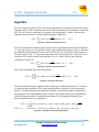
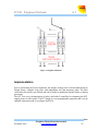
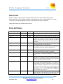
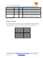
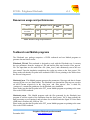
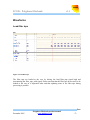
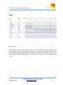
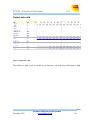
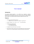
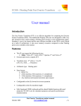
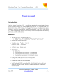
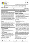
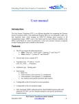
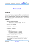
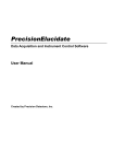
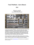
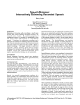
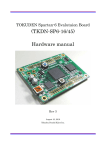
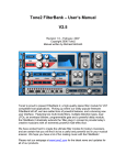
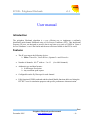
FC108 - Polyphase filterbank
v1.1
User manual
Introduction
The polyphase filterbank algorithm is a very efficient way to implement a uniformly
distributed multi-channel filterbank using a Fast Fourier Transform (FFT). This Intellectual
Property (IP) core was designed to process data in real time up to rates of 1GSPS in Virtex-4
devices. Sundance’s core is the fastest and the most efficient available in the FPGA world.
Features
•
This IP core targets the following devices:
¾ Xilinx: Virtex-IITM, Virtex-II ProTM, Spartan-3TM and Virtex-4TM
•
Number of channels: M=2m with m = 3 to 12
•
Arithmetic type and data formats :
¾ 16-bit integer fixed point
¾ Any resolution upon request
•
Configurable on the fly filter taps for each channel
•
Fully functional VHDL testbench and the related Matlab functions delivered along the
FFT/IFFT core for simulation purposes and specific performance characterization.
(8 to 4096 channels)
Fast
December 2005
Polyphase filterbank product manual
www.sundance.com
-1-
FC108 - Polyphase filterbank
v1.1
Algorithm
The Fast Fourier Transform (FFT) is an efficient algorithm for computing the Discrete Fourier
Transform (DFT), that is transform data between the time and frequency domains. Consider the
DFT X(k) of a data set consisting of a sequence x(n) multiplied by a window function h(n)
implemented in the form of a Finite Impulse Response (FIR) filter.
X ( k ) = ∑n =0 h( n ). x ( n ) e
N −1
− j 2πnk
N
with k = 0, 1, …, N-1
Equation 1: Windowed original function
The Fourier transform computing effort required by the implementation described in Equation
1 is very large. However, it is possible to apply some mathematical tricks to reduce it and make
the algorithm implementation fit more easily in FPGA devices. For an FFT implementation, k
takes the values 0 to N-1. To prune the output data only a subset of the X(k) values need to be
calculated. If N can be factored as rM and only every rth value of X(k) is taken then the
calculation is reduced to:
X ( k ' ) = ∑n =0 h ( n ). x ( n ) e
N −1
− j 2πrnk '
N
with k’ = 0, 1, …, M-1
Equation 2: Windowed pruned function
This can be rearranged in the following manner:
r −1 M −1
X ( k ' ) = ∑ ∑ h( n + mM ). x ( n + mM ) e
− j 2πnk '
M
with k’ = 0, 1, …, M-1
m =0 n =0
Equation 3: Polyphase filterbank
The total workload needed to implement the windowing is unchanged but the FFT is reduced
to a single M-point transform. This can be implemented by a structure as the one shown in
Figure 1. The data filtering in the polyphase filterbank is performed using two independent
filter paths for the In and Quadrature phase samples. This further reduces the computational
load by halving the number of multiplications required. The Polyphase filterbank core is
therefore implemented as per Equation 4.
r −1 M −1
X ( k ' ) = ∑ ∑ ( hI ( n + mM ). xI ( n + mM ) + hQ ( n + mM ). xQ ( n + mM )) e
− j 2πnk '
M
m =0 n =0
with k’ = 0, 1, …, M-1. With xI = I_in and xQ=Q_in. With hI= I_filter_taps and hQ= Q_filter_taps
Equation 4: Polyphase filterbank implementation
Fast
December 2005
Polyphase filterbank product manual
www.sundance.com
-2-
FC108 - Polyphase filterbank
v1.1
Figure 1: Polyphase filterbank
Implementation
Prior to performing the Fourier transform, the samples undergo first an M-decimation and are
filtered using a complex 8-tap filter with independent real and imaginary paths. The filter
coefficients are entirely user defined and can be loaded or updated at anytime before or during
processing.
The FFT core uses a decomposition of radix-4 and radix-2 butterflies for computing the DFT,
ranging from 8 to 4096 points. The FFT length is a user programmable parameter and it can be
changed without the need to reconfigure the FPGA.
Fast
December 2005
Polyphase filterbank product manual
www.sundance.com
-3-
FC108 - Polyphase filterbank
v1.1
Data format
The data format is 16-bit integer fixed point and is kept as such for all processing stages.
Please note that the FFT requires normally a 2-bit growth per radix-4 stage, therefore, a scaling
coefficient is user programmable in order to keep the best accuracy as possible.
Other data formats are available upon request.
Ports definitions
Port name
Port width
Direction
Description
clk
1
Input
Clock
reset
1
Input
Asynchronous reset (active high)
start
1
Input
stop
1
Input
load_filter_taps
1
Output
Start signal (active high). Start is asserted for one clock cycle
to start the core. It needs to be asserted once at the beginning
unless the core has been given a stop command. The data on
I_in and Q_in must be valid on the same clock cycle as start
is asserted.
Stop is asserted for one clock cycle to interrupt the data
processing and put the core in an idle state.
Load filter pass signal (active high). A new filter tap is loaded
to the internal core memory when this signal is active.
I_filter_taps
16
input
Q_filter_taps
16
Input
Filter_taps_addr
15
Input
FFT_scaling
4
Input
NB_CH
3
Input
In phase filter taps bus. The In phase filter taps coefficients
are loaded to the internal core memory via this bus.
Quadrature phase filter taps bus. The Quadrature phase filter
taps coefficients are loaded to the internal core memory via
this bus.
Filter taps address bus. The filter taps will be written to the
address provided on this bus. The three Least Significant Bits
(2 downto 0), represent the tap indexing in a filter. The Most
Significant Bits represent the filter number.
FFT scaling. The scaling schedule is specified with two bits
for every pair of the FFT radix-2 stages. For example, a
scaling schedule for Number of channels=256 could be [2 2 2
3]. When the number of channels is not a power of 4, the
maximum bit growth for the last stage is one bit. For instance,
[0 2 2 2 2] or [1 2 2 2 2] are valid scaling schedules for
N=512, but [2 2 2 2 2] is invalid. The two MSBs of
FFT_scaling can only be 00 or 01.
Number of channels. This parameter is the number of
channels present in the signal and is equivalent to the FFT
length. The value of NB_CH is log2(number of channels).
Fast
December 2005
Polyphase filterbank product manual
www.sundance.com
-4-
FC108 - Polyphase filterbank
v1.1
I_in
16
Input
Input data bus: In Phase component
Q_in
16
Input
Input data bus: Quadrature Phase component
I_out
16
Output
Output data bus: In Phase component
Q_out
16
Output
Output data bus: Quadrature component
data_valid
1
Output
Data valid signal: data on the I_out and Q_out bus are valid
overflow
1
Output
Overflow: indicates if the FFT calculation has overflowed
during processing. If an overflow is detected the results
should be discarded and it is recommended to increase the
FFT scaling factor (FFT_scaling) for further processing.
Table 1 : Ports definition
Number of channels
The Number of channels is a parameter fed to the core. This parameter can be either constant
or can be changed on the fly in order to perform calculations with a different number of
channels. The following table shows the FFTlength code for a given transform length:
Number of Channels
NB_CH code
8
16
32
64
128
256
512
1024
2048
4096
00011
00100
00101
00110
00111
01000
01001
01010
01011
01100
Table 2 : NB_CH codes
Fast
December 2005
Polyphase filterbank product manual
www.sundance.com
-5-
FC108 - Polyphase filterbank
v1.1
Resources usage and performances
Device
Virtex-II Pro
XC2VP40 -7
Virtex-II
XC2V8000
Slices
Multipliers 18x18
Block RAMs
18Kb
Fmax
5,901
36
157
125.0MHz
5,230
36
157
106.7 MHz
Table2 : Resources usage and performances
Testbench and Matlab programs
The Filterbank core package comprises a VHDL testbench and two Matlab programs to
generate data and check results.
Filterbank_TB.vhd: This testbench is designed to work with the Filterbank core. It extracts
the core parameters from the ‘settings.txt’ file and load the filter taps from the ‘filter_taps.txt’
file. The input data are also read from a file (‘data_in.txt’) and continuously sent to the core
once started. Upon the simulation completion, the results are written to the ‘data_out.txt’ file.
Please make sure that the file paths in the testbench VHDL file are pointing to the folder where
the files are being stored.
filterbank_in.m : This Matlab program generates the parameters, filter taps and data in format
expected by the core (see Data format). The filterbank core data and the filter taps are saved in
an ASCII format respectively in the ‘data_in.txt’ and ‘filter_taps.txt’ files. A third file,
‘settings.txt’, contains the parameters for thefilterbank core simulation.
Please make sure that the file paths in the FFT_test.m Matlab program are pointing to the same
files as the VHDL testbench.
filterbank_out.m : This Matlab program reads the files generated by the filterbank_in.m
program as well the results of the simulation from the ‘data_out.txt’ file. It then performs the
data processing as per Equation 4 and calculates for each data batch the Signal To Noise Ratio
(SNR) that is written to the ‘SNR.txt’ file.
Please make sure that the file paths in the FFT_test.m Matlab program are pointing to the same
files as the VHDL testbench.
Fast
December 2005
Polyphase filterbank product manual
www.sundance.com
-6-
FC108 - Polyphase filterbank
v1.1
Waveforms
Load filter taps
taps
Figure 2: Load filter taps
The filter taps are loaded to the core by driving the load_filter_taps signal high and
incrementing the filter_taps_addr signal. Please note that that the filter taps do not need to be
loaded to the core in a sequential order and that updating some of the filter taps during
processing is possible.
Fast
December 2005
Polyphase filterbank product manual
www.sundance.com
-7-
FC108 - Polyphase filterbank
v1.1
Start
Figure 3: Start
Once the filter taps have been loaded to the core, a start pulse generated by the user interface
will signify the start of the processing inside the core. The user parameters (NB_CH and
FFT_scaling) and the first data sample are registered inside the core on the same clock cycle as
the start pulse. Data samples must then be valid at the input of the core every subsequent clock
cycle.
Fast
December 2005
Polyphase filterbank product manual
www.sundance.com
-8-
FC108 - Polyphase filterbank
v1.1
Output data valid
Figure 4: output data valid
The results are valid on the I_out and Q_out data buses when the data_valid signal is high.
Fast
December 2005
Polyphase filterbank product manual
www.sundance.com
-9-
FC108 - Polyphase filterbank
v1.1
References
[1] Bellanger and Daguet, ‘TDM-FDM Transmultiplexer: Digital Polyphase and FFT’, IEEE
Trans Com, Vol Com-22, No 9, pages 1199-1205, Sept 1974
[2] Crochiere and Rabiner, ‘Multirate Digital Signal Processing’, Prentice-Hall, NJ, 1983
[3] John Button ‘Multi-resolution FX correlator’, CSIRO Telecommunications and Industrial
Physics, ALMA memo 447, 2003
Fast
December 2005
Polyphase filterbank product manual
www.sundance.com
- 10 -