1
Allen-Bradley
ControlNet
PLC-5
Programmable
Controllers
(Cat. Nos. 1785-L20C15,
-L40C15, -L80C15)
product icon
User
Manual
Phase 1.5
Important User Information
6ROLGVWDWHHTXLSPHQWKDVRSHUDWLRQDOFKDUDFWHULVWLFVGLIIHULQJIURP
WKRVHRIHOHFWURPHFKDQLFDOHTXLSPHQW³6DIHW\*XLGHOLQHVIRUWKH
$SSOLFDWLRQ,QVWDOODWLRQDQG0DLQWHQDQFHRI6ROLG6WDWH&RQWUROV´
3XEOLFDWLRQ6*,GHVFULEHVVRPHLPSRUWDQWGLIIHUHQFHVEHWZHHQ
VROLGVWDWHHTXLSPHQWDQGKDUGZLUHGHOHFWURPHFKDQLFDOGHYLFHV
%HFDXVHRIWKLVGLIIHUHQFHDQGDOVREHFDXVHRIWKHZLGHYDULHW\RI
XVHVIRUVROLGVWDWHHTXLSPHQWDOOSHUVRQVUHVSRQVLEOHIRUDSSO\LQJ
WKLVHTXLSPHQWPXVWVDWLVI\WKHPVHOYHVWKDWHDFKLQWHQGHGDSSOLFDWLRQ
RIWKLVHTXLSPHQWLVDFFHSWDEOH
,QQRHYHQWZLOO5RFNZHOO$XWRPDWLRQEHUHVSRQVLEOHRUOLDEOHIRU
LQGLUHFWRUFRQVHTXHQWLDOGDPDJHVUHVXOWLQJIURPWKHXVHRU
DSSOLFDWLRQRIWKLVHTXLSPHQW
7KHH[DPSOHVDQGGLDJUDPVLQWKLVPDQXDODUHLQFOXGHGVROHO\IRU
LOOXVWUDWLYHSXUSRVHV%HFDXVHRIWKHPDQ\YDULDEOHVDQGUHTXLUHPHQWV
DVVRFLDWHGZLWKDQ\SDUWLFXODULQVWDOODWLRQ5RFNZHOO$XWRPDWLRQ
FDQQRWDVVXPHUHVSRQVLELOLW\RUOLDELOLW\IRUDFWXDOXVHEDVHGRQWKH
H[DPSOHVDQGGLDJUDPV
1RSDWHQWOLDELOLW\LVDVVXPHGE\5RFNZHOO$XWRPDWLRQZLWKUHVSHFW
WRXVHRILQIRUPDWLRQFLUFXLWVHTXLSPHQWRUVRIWZDUHGHVFULEHGLQ
WKLVPDQXDO
5HSURGXFWLRQRIWKHFRQWHQWVRIWKLVPDQXDOLQZKROHRULQSDUW
ZLWKRXWZULWWHQSHUPLVVLRQRI5RFNZHOO$XWRPDWLRQLVSURKLELWHG
7KURXJKRXWWKLVPDQXDOZHXVHQRWHVWRPDNH\RXDZDUHRIVDIHW\
FRQVLGHUDWLRQV
$77(17,21 ,GHQWLILHVLQIRUPDWLRQDERXWSUDFWLFHV
RUFLUFXPVWDQFHVWKDWFDQOHDGWRSHUVRQDOLQMXU\RU
GHDWKSURSHUW\GDPDJHRUHFRQRPLFORVV
$WWHQWLRQVKHOS\RX
LGHQWLI\DKD]DUG
DYRLGWKHKD]DUG
UHFRJQL]HWKHFRQVHTXHQFHV
,PSRUWDQW,GHQWLILHVLQIRUPDWLRQWKDWLVHVSHFLDOO\LPSRUWDQWIRU
VXFFHVVIXODSSOLFDWLRQDQGXQGHUVWDQGLQJRIWKHSURGXFW
(WKHUQHWLVDUHJLVWHUHGWUDGHPDUNRI,QWHO&RUSRUDWLRQ;HUR[&RUSRUDWLRQDQG' LJLWDO(TXLSP HQW
&RUSRUDWLRQ
&RQWURO1HWLVDWUDGHPDUNRI&RQWURO1HW,QWHUQDWLRQDO
'DWD+LJKZD\3OXV'+561HW:RU[)/(;,23/&3/&3/&3/&3/&&
/&/&((DQG(DUH
WUDGHP DUNVRI5RFNZHOO$XWRPDWLRQ
$OOHQ%UDGOH\LVDWUDGHPDUNRI5RFNZHOO$XWRP DWLRQDFRUHEXVLQHVVRI5RFNZHOO,QWHUQDWLRQDO
&RUSRUDWLRQ
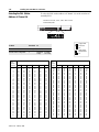
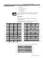
Summary of Changes
Summary of Changes
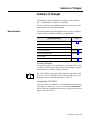
7KHLQIRUPDWLRQEHORZVXPPDUL]HVWKHFKDQJHVWRWKH&RQWURO1HW
3/&3URJUDPPDEOH&RQWUROOHUV8VHU0DQXDO
7RKHOS\RXILQGQHZDQGXSGDWHGLQIRUPDWLRQORRNIRUWKHUHYLVLRQ
EDUVDVVKRZQWRWKHOHIWRIWKLVSDUDJUDSK
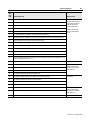
7KHIROORZLQJWDEOHDQGSDUDJUDSKVGHVFULEHQHZIHDWXUHVXSGDWHG
H[LVWLQJIHDWXUHVDQGZKHUHWRILQGWKLVQHZLQIRUPDWLRQ
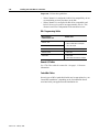
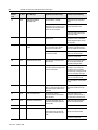
New Information
For This New Information
ControlNet MSGs to DH+ and Ethernet Devices
See
Chapter 4
ControlNet Unsolicited MSGs to RSLinx
Option to Close Connection when MSG is Done
Processor Specifications
Appendix A
I/O Map-Entry Status Words
Appendix D
Error Messages
ControlNet Diagnostics File Layout
Appendix F
ControlNet Hot Backup
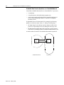
<RXFDQSDLUWRJHWKHUWZR&RQWURO1HWSURFHVVRUVHLWKHUD3/&&
RU&DQGDVVLJQRQHRIWKHSURFHVVRUVDVWKHSULPDU\FRQWUROOHU
DQGWKHRWKHUDVDVHFRQGDU\EDFNXSFRQWUROOHU
E
MOR
7KH&+%0&RQWURO1HW%DFNXS&DUWULGJHLVUHTXLUHGIRUHDFK
SURFHVVRU)RUPRUHLQIRUPDWLRQUHIHUWRWKH&RQWURO1HW3/&+RW
%DFNXS6\VWHP8VHU0DQXDOSXEOLFDWLRQ
Catalog Number 1785-L60C15
7KLVUHOHDVHRIWKH&RQWURO1HW3/&3URJUDPPDEOH&RQWUROOHUVGRHV
QRWLQFOXGHWKH/&KRZHYHURQO\WKHQHZLQIRUPDWLRQLQ
WKLVXVHUPDQXDODVKLJKOLJKWHGDERYHGRHVQRWDSSO\WRWKHSUHYLRXV
UHOHDVHRIWKH/&
1785-6.5.22 - February 1999
Preface
Preface
7KLVPDQXDOGHVFULEHVKRZWRLQVWDOO\RXUSURFHVVRUDQGKRZWRSODQ
IRUFRQILJXUHDQGXVHWKHIHDWXUHVRID3/&&3/&&
RU3/&&SURJUDPPDEOHFRQWUROOHUWKDWDUHXQLTXHWRWKH
&RQWURO1HWQHWZRUN
Introduction
:KHQZHUHIHUWR&RQWURO1HWSURFHVVRUVLQWKLVPDQXDOZHPHDQWKH
SKDVHSURFHVVRUV
E
MOR
Audience
/&
/&
/&
)RUGHWDLOHGLQIRUPDWLRQDERXWIHDWXUHVWKDWWKH3/&&&
DQG&SURJUDPPDEOHFRQWUROOHUVVKDUHZLWKWKH3/&
SURFHVVRUVVHHWKH(QKDQFHGDQG(WKHUQHW3/&
3URJUDPPDEOH&RQWUROOHUV8VHU0DQXDOSXEOLFDWLRQ
7KHLQIRUPDWLRQLQWKLVPDQXDOLVLQWHQGHGIRUHQJLQHHUVDQG
WHFKQLFLDQVZKRDUHLQVWDOOLQJSURJUDPPLQJDQGPDLQWDLQLQJD
FRQWUROV\VWHPWKDWLQFOXGHVD3/&&&RU&
SURJUDPPDEOHFRQWUROOHU
<RXVKRXOGKDYHDEDFNJURXQGLQFRQWUROV\VWHPDSSOLFDWLRQVDQGD
EDVLFNQRZOHGJHRI
SURJUDPPDEOHUHDOWLPHFRQWUROV\VWHPV
WKH3/&FRQWUROV\VWHP
\RXURSHUDWLRQ¶VUHTXLUHGV\VWHPVDQGDSSOLFDWLRQV
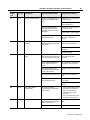
Contents
If you want to read about:
Go to:
Installing your ControlNet PLC-5 processor
Setting switches
Installing communication links
Chapter 1
Planning to use your ControlNet PLC-5 processor
Understanding ControlNet I/O
Using a ControlNet PLC-5 processor
Chapter 2
Using programming software to configure your ControlNet system
Chapter 3
Programming your ControlNet system
Chapter 4
Monitoring and troubleshooting your ControlNet system
Using the status indicators
Chapter 5
Processor specifications
Appendix A
1785-6.5.22 - February 1999
P-2
Preface
If you want to read about:
Go to:
Processor status file
Appendix B
ControlNet instructions
Appendix C
ControlNet I/O map-table entry status words and error messages
Appendix D
Fault codes
Appendix E
ControlNet diagnostics file layout
Appendix F
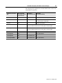
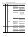
Terminology
Term
Description
Actual Packet Interval (API)
the actual time it takes for the ControlNet network to update the requested data. The largest
binary multiple of the Network Update Time (NUT), smaller or equal to the Requested Packet
Interval (RPI).
ControlNet network
communication architecture that allows the exchange of data between Allen-Bradley
Company, Inc. products and certified third-party products
ControlNet PLC-5 processors
references PLC-5/20C, -5/40C, and -5/80C processors phase 1.5
connection
opened communication path between two nodes on a ControlNet network
Data Input File (DIF)
integer file used by ControlNet PLC-5 processors to store discrete and non-discrete input
data. The DIF cannot be forced
Data Output File (DOF)
integer file used by ControlNet PLC-5 processors to store discrete and non-discrete output
data. The DOF cannot be forced
discrete I/O data transfer
type of data transfer in which single units of I/O have discrete relationships with values in
the processor’s data table; uses the processor’s input- and output-image tables (I and O
files); configured on a per-node basis in the ControlNet I/O map table
frame
single data transfer on a ControlNet link
drop cable
cable that connects a ControlNet node to the trunk cable; integral part of 1786 taps
I/O map table
table that you configure using the programming software to map data from an I/O chassis
and other devices on the ControlNet network to particular data-table file addresses
keeper
device that stores and distributes ControlNet configuration data to all nodes on the network.
A minimum of one keeper device is required on each ControlNet network.
link
collection of ControlNet nodes with unique network addresses in the range of 01-99; segments
connected by repeaters make up a link; links connected by bridges make up a network
map-table entry
one entry in the I/O map table that you configure using the programming software to map
data from one I/O chassis or other device on ControlNet to particular data-table file
addresses
network access port (NAP)
port that provides a temporary ControlNet-network connection through an RJ-45 connector
network address
node’s address on the ControlNet network
network update interval (NUI)
single occurrence of the ControlNet Network Update Time (NUT)
network update time (NUT)
smallest repetitive time interval in which data can be sent on the ControlNet network
node
port of a physical device connecting to the ControlNet network that requires a network
address in order to function on the network; a link may contain a maximum of 99 nodes
1785-6.5.22 - February 1999
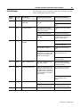
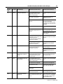
Preface
Term
P-3
Description
non-discrete I/O data transfer
type of data transfer in which blocks of data transferred to or from I/O modules use integer
input and output data-table files that you specify; scheduled transfers are configured in the
ControlNet I/O map table, unscheduled transfers make use of ControlNet I/O Transfer (CIO)
instructions
owner
device that controls the outputs of an adapter
redundant media
dual-cable system that allows you to receive the best signal over a ControlNet network
repeater
two-port active physical-layer device that reconstructs and retransmits all traffic that it
hears on one ControlNet segment to another segment
Requested Packet Interval
(RPI)
the maximum time allowed for the ControlNet network to update requested data. The RPI is
user-selectable on a per connection basis.
scheduled maximum node
(SMAX)
the maximum ControlNet node number that can transmit and receive scheduled data
scheduled transfers
deterministic and repeatable transfers that are continuous and asynchronous to the ladderlogic program scan
segment
trunkline section of ControlNet network with terminators at each end; a segment does not
include repeaters; segments connected by repeaters make up a link
tap
component that connects products to the ControlNet trunk cable; a tap is required for each
node and for each side of a repeater
terminator
75W resistor—mounted in a BNC plug—placed on each end of a ControlNet segment to
prevent reflections from occurring at the ends of the cable
trunk cable
bus or central part of the ControlNet cable system
trunk-cable section
length of trunk cable between any two ControlNet taps
unscheduled maximum node
(UMAX)
the maximum ControlNet node number that can transmit and receive unscheduled data
unscheduled transfers
non-deterministic data transfers through ladder-initiated communication or programming
devices
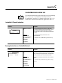
Conventions
7KLVLFRQ
E
MOR
LQGLFDWHVWKDWWKHFXUUHQWWRSLFLV
GLVFXVVHGIXUWKHULQWKH
SXEOLFDWLRQVUHIHUHQFHG
1785-6.5.22 - February 1999
P-4
Preface
Related PLC-5 Publications
7KH3/&SURJUDPPDEOHFRQWUROOHUDQG&RQWURO1HW
GRFXPHQWDWLRQLVRUJDQL]HGLQWRPDQXDOVDFFRUGLQJWRWKHWDVNVWKDW
\RXSHUIRUP
Publication
Publication Number
Enhanced PLC-5 Processor System Overview
1785-2.36
Enhanced and Ethernet PLC-5 Programmable Controllers User
Manual
1785-6.5.12
ControlNet PLC-5 Programmable Controllers User Manual
1785-6.5.22
ControlNet Cable system Planning and Installation Manual
1785-6.2.1
ControlNet PlC-5 Programmable Controllers Quick Start
1785-10.6
1785-PLC-5 Programmable Controllers Quick Reference
1785-7.1
)RUPRUHLQIRUPDWLRQDERXW3/&SURJUDPPDEOHFRQWUROOHUVRU
WKHDERYHSXEOLFDWLRQVFRQWDFW\RXUORFDO5RFNZHOO$XWRPDWLRQVDOHV
RIILFHRUGLVWULEXWRU
Related ControlNet Publications
)RUGHWDLOHGLQIRUPDWLRQDERXWGLIIHUHQWDVSHFWVRISODQQLQJDQG
LQVWDOOLQJ\RXU&RQWURO1HWQHWZRUNVHHWKHIROORZLQJSXEOLFDWLRQV
Publication
Publication Number
ControlNet Cable System Component List
AG-2.2
ControlNet Coax Cable System Planning and Installation Manual
1786-6.2.1
ControlNet Coax Tap Installation Instructions
1786-2.3
ControlNet Network Access Cable Installation Instructions
1786-2.6
ControlNet Repeater Installation Instructions
1786-2.7
ControlNet System Overview
1786-2.12
ControlNet PLC-5 Hot Backup System User Manual
1785-6.5.24
Industrial Automation Wiring and Grounding Guidelines
1770-4.1
)RUPRUHLQIRUPDWLRQDERXWWKHDERYHSXEOLFDWLRQVFRQWDFW\RXUORFDO
5RFNZHOO$XWRPDWLRQVDOHVRIILFHRUGLVWULEXWRU
1785-6.5.22 - February 1999
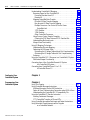
Table of Contents
Installing Your ControlNet
PLC-5 Processor
Chapter 1
Planning to Use Your ControlNet
PLC-5 Processor
Chapter 2
Using This Chapter . . . . . . . . . . . . . . . . . . . . . . . . . . . . . . . . . . . . . . 1-1
Before You Begin . . . . . . . . . . . . . . . . . . . . . . . . . . . . . . . . . . . . . . . . 1-2
Handling the Processor . . . . . . . . . . . . . . . . . . . . . . . . . . . . . . . . . . . 1-3
Compliance to European Union Directives . . . . . . . . . . . . . . . . . . . . . 1-3
EMC Directive . . . . . . . . . . . . . . . . . . . . . . . . . . . . . . . . . . . . . . . . 1-3
Low Voltage Directive . . . . . . . . . . . . . . . . . . . . . . . . . . . . . . . . . . 1-3
Identifying ControlNet PLC-5 Processor Components . . . . . . . . . . . . . 1-4
Setting the I/O Chassis Backplane Switches. . . . . . . . . . . . . . . . . . . . 1-6
Setting the I/O Chassis Configuration Plug . . . . . . . . . . . . . . . . . . . . . 1-7
Installing Keying Bands for the Processor. . . . . . . . . . . . . . . . . . . . . . 1-7
Installing and Disposing of the Processor Battery . . . . . . . . . . . . . . . . 1-8
Installing or Removing the Processor Battery . . . . . . . . . . . . . . . . . 1-8
Replacing the Battery. . . . . . . . . . . . . . . . . . . . . . . . . . . . . . . . . . . 1-9
Disposing of the Battery . . . . . . . . . . . . . . . . . . . . . . . . . . . . . . . . . 1-9
Selecting the DH+ Station Address of Channel 1A . . . . . . . . . . . . . . 1-10
Specifying the Serial Interface of Channel 0 . . . . . . . . . . . . . . . . . . . 1-11
Selecting the ControlNet Network Address of Channel 2 . . . . . . . . . 1-11
Inserting/Removing the Processor into/from the I/O Chassis. . . . . . . 1-12
Installing a Remote I/O Link . . . . . . . . . . . . . . . . . . . . . . . . . . . . . . . 1-12
Installing a DH+ Link . . . . . . . . . . . . . . . . . . . . . . . . . . . . . . . . . . . . 1-14
Connecting to a ControlNet Network . . . . . . . . . . . . . . . . . . . . . . . . 1-15
Connecting a Programming Terminal . . . . . . . . . . . . . . . . . . . . . . . . 1-16
DH+ Connection . . . . . . . . . . . . . . . . . . . . . . . . . . . . . . . . . . . . . 1-16
Serial Channel . . . . . . . . . . . . . . . . . . . . . . . . . . . . . . . . . . . . . . . 1-17
ControlNet Connection . . . . . . . . . . . . . . . . . . . . . . . . . . . . . . . . . 1-18
Selecting Appropriate Cables . . . . . . . . . . . . . . . . . . . . . . . . . . . . . . 1-19
Serial Cables . . . . . . . . . . . . . . . . . . . . . . . . . . . . . . . . . . . . . . . . 1-19
DH+ Programming Cables . . . . . . . . . . . . . . . . . . . . . . . . . . . . . . 1-20
Remote I/O Cables . . . . . . . . . . . . . . . . . . . . . . . . . . . . . . . . . . . . 1-20
ControlNet Cables . . . . . . . . . . . . . . . . . . . . . . . . . . . . . . . . . . . . 1-20
Using This Chapter . . . . . . . . . . . . . . . . . . . . . . . . . . . . . . . . . . . . . . 2-1
Understanding ControlNet I/O. . . . . . . . . . . . . . . . . . . . . . . . . . . . . . . 2-1
Scheduled Data-Transfer Operations on a ControlNet Network . . . . 2-2
Unscheduled Data-Transfer Operations on a ControlNet Network . . 2-3
Using I/O Forcing Operations . . . . . . . . . . . . . . . . . . . . . . . . . . . . . 2-6
Using Immediate Data-Transfer Operations . . . . . . . . . . . . . . . . . . 2-7
Publication 1785-6.5.22 - February 1999
toc–ii
Table of Contents – ControlNet PLC-5 Programmable Controllers
Understanding ControlNet I/O Mapping . . . . . . . . . . . . . . . . . . . . . . . 2-8
Reserving Space for Non-ControlNet I/O. . . . . . . . . . . . . . . . . . . . . 2-8
Processor-Resident Local I/O . . . . . . . . . . . . . . . . . . . . . . . . . . . 2-9
Remote I/O. . . . . . . . . . . . . . . . . . . . . . . . . . . . . . . . . . . . . . . . . 2-9
Mapping ControlNet Data Transfer . . . . . . . . . . . . . . . . . . . . . . . . 2-10
Discrete I/O Data-Transfer Mapping . . . . . . . . . . . . . . . . . . . . . 2-13
Non-discrete I/O Data-Transfer Mapping . . . . . . . . . . . . . . . . . 2-13
Multiple Processors Can Control I/O on the Same
ControlNet Link . . . . . . . . . . . . . . . . . . . . . . . . . . . . . . . . . . 2-14
1771 Modules . . . . . . . . . . . . . . . . . . . . . . . . . . . . . . . . . . . . . 2-14
1794 Modules . . . . . . . . . . . . . . . . . . . . . . . . . . . . . . . . . . . . . 2-16
Other ControlNet Processors . . . . . . . . . . . . . . . . . . . . . . . . . . 2-17
Using Process Control Sample Complete . . . . . . . . . . . . . . . . . . . 2-18
Clearing the PCSC New Data and PCSC Overflow Bits. . . . . . . . 2-20
Understanding Multicast Inputs . . . . . . . . . . . . . . . . . . . . . . . . . . 2-20
Merged-Save Functionality. . . . . . . . . . . . . . . . . . . . . . . . . . . . . . 2-21
Using I/O Mapping Techniques. . . . . . . . . . . . . . . . . . . . . . . . . . . . . 2-21
Understanding Discrete Mapping . . . . . . . . . . . . . . . . . . . . . . . . . 2-22
Optimizing the I/O Image Table . . . . . . . . . . . . . . . . . . . . . . . . . . 2-23
Optimizing the I/O Image Table without Slot Complementary . . 2-23
Optimizing the I/O Image Table with Slot Complementary. . . . . 2-28
Summary . . . . . . . . . . . . . . . . . . . . . . . . . . . . . . . . . . . . . . . . . . . 2-29
Using the ControlNet PLC-5 Processor in a ControlNet I/O System . . 2-31
Distributed Keeper Functionality. . . . . . . . . . . . . . . . . . . . . . . . . . 2-33
Converting from a Non-ControlNet Remote I/O System
to a ControlNet I/O System . . . . . . . . . . . . . . . . . . . . . . . . . 2-33
Converting from ControlNet Phase 1.0 or 1.25
to ControlNet Phase 1.5 . . . . . . . . . . . . . . . . . . . . . . . . . . . 2-34
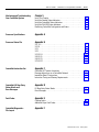
Configuring Your
ControlNet System
Chapter 3
Programming Your
ControlNet System
Chapter 4
Publication 1785-6.5.22 - February 1999
Using This Chapter . . . . . . . . . . . . . . . . . . . . . . . . . . . . . . . . . . . . . . 4-1
Using ControlNet Message Instructions . . . . . . . . . . . . . . . . . . . . . . . 4-1
Multihop Messaging Via the MSG Instruction . . . . . . . . . . . . . . . . . 4-2
Option to Close Communication Connection when MSG is Done . . . 4-3
Understanding the ControlNet PLC-2 Compatibility File . . . . . . . . . 4-3
Using the ControlNet I/O Transfer Instruction . . . . . . . . . . . . . . . . . . . 4-3
Sending Continuous Messages. . . . . . . . . . . . . . . . . . . . . . . . . . . . 4-5
1771 ControlNet Transfers in PIIs and STIs. . . . . . . . . . . . . . . . . . . 4-5
Using ControlNet Immediate Data Input and Output Instructions. . . . . 4-6
Using Selectable Timed Interrupts with a Program
on a ControlNet Network . . . . . . . . . . . . . . . . . . . . . . . . . . . . 4-9
Table of Contents – ControlNet PLC-5 Programmable Controllers
Monitoring and Troubleshooting
Your ControlNet System
Chapter 5
Processor Specifications
Appendix A
Processor Status File
Appendix B
toc–iii
Using This Chapter . . . . . . . . . . . . . . . . . . . . . . . . . . . . . . . . . . . . . . 5-1
Using the General Status Indicators . . . . . . . . . . . . . . . . . . . . . . . . . . 5-1
Using the ControlNet Status Indicators . . . . . . . . . . . . . . . . . . . . . . . . 5-3
Using the DH+/RIO Status Indicators . . . . . . . . . . . . . . . . . . . . . . . . . 5-5
Monitoring ControlNet Configuration and Status. . . . . . . . . . . . . . . . . 5-6
S:0 - S:2 . . . . . . . . . . . . . . . . . . . . . . . . . . . . . . . . . . . . . . . . . . . . . . B-1
S:3-10. . . . . . . . . . . . . . . . . . . . . . . . . . . . . . . . . . . . . . . . . . . . . . . . B-2
S:11 . . . . . . . . . . . . . . . . . . . . . . . . . . . . . . . . . . . . . . . . . . . . . . . . . B-3
S:12 . . . . . . . . . . . . . . . . . . . . . . . . . . . . . . . . . . . . . . . . . . . . . . . . . B-4
S:13-S:24 . . . . . . . . . . . . . . . . . . . . . . . . . . . . . . . . . . . . . . . . . . . . B-10
S:26-S:35 . . . . . . . . . . . . . . . . . . . . . . . . . . . . . . . . . . . . . . . . . . . . B-11
S:36-S:78 . . . . . . . . . . . . . . . . . . . . . . . . . . . . . . . . . . . . . . . . . . . . B-12
S:79-S127. . . . . . . . . . . . . . . . . . . . . . . . . . . . . . . . . . . . . . . . . . . . B-13
ControlNet Instruction Set
Appendix C
ControlNet I/O Transfer Instruction
. . . . . . . . . . . . . . . . . . . . . . . . C-1
Message Instructions on a ControlNet Network . . . . . . . . . . . . . . . C-1
Immediate Data I/O Instructions
. . . . . . . . . . . . . . . . . . . . . . . . . C-2
Instruction Timing and Memory Requirements . . . . . . . . . . . . . . . . . . C-2
ControlNet I/O Map-Entry
Status Words and
Error Messages
Appendix D
Fault Codes
Appendix E
I/O Map-Entry Status Words. . . . . . . . . . . . . . . . . . . . . . . . . . . . . . . . D-1
Error Messages . . . . . . . . . . . . . . . . . . . . . . . . . . . . . . . . . . . . . . . . . D-4
Clearing Faults. . . . . . . . . . . . . . . . . . . . . . . . . . . . . . . . . . . . . . . . . . E-1
Additional Major Fault Codes . . . . . . . . . . . . . . . . . . . . . . . . . . . . . . . E-2
ControlNet Diagnostics
File Layout
Appendix F
Publication 1785-6.5.22 - February 1999
Chapter
1
Installing Your ControlNet
PLC-5 Processor
Using This Chapter
E
MOR
If you want to read about:
Go to page:
Completing the preliminary setup
1-2
Checking the contents of the processor package
1-2
Handling the processor
1-3
Identifying the processor channels/connectors
1-4
Setting the I/O chassis backplane switches
1-6
Setting the I/O chassis configuration plug
1-7
Installing keying bands for the processor
1-7
Installing and disposing of the processor battery
1-8
Selecting the Data Highway Plus™ (DH+™) station address
of Channel 1A
1-10
Specifying the serial interface for Channel 0
1-11
Selecting the ControlNet network address of Channel 2
1-11
Inserting/removing the processor into/from the I/O chassis
1-12
Installing a remote I/O link
1-12
Installing a DH+ link
1-14
Connecting to a ControlNet network
1-15
Connecting a programming terminal
1-16
Selecting appropriate cables
1-19
)RUGHWDLOHGLQIRUPDWLRQDERXWLQVWDOOLQJFKDVVLVDQGDGDSWHUVVHHWKH
(QKDQFHGDQG(WKHUQHW3/&3URJUDPPDEOH&RQWUROOHUV8VHU
0DQXDOSXEOLFDWLRQ
1785-6.5.22 - February 1999
1-2
Installing Your ControlNet PLC-5 Processor
%HIRUHLQVWDOOLQJ\RXU&RQWURO1HW3/&SURFHVVRU
Before You Begin
&RPSOHWHWKHIROORZLQJ
E
MOR
GHWHUPLQHWKHSURSHUHQYLURQPHQW
FRQILJXUHWKHSURSHUJURXQGLQJ
URXWHWKHFRQGXFWRUVSURSHUO\
)RUGHWDLOHGLQIRUPDWLRQDERXWFRPSOHWLQJWKHVHWDVNVVHHWKH
(QKDQFHGDQG(WKHUQHW3/&3URJUDPPDEOH&RQWUROOHUV8VHU
0DQXDOSXEOLFDWLRQ
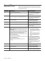
&KHFN\RXUSURFHVVRUSDFNDJHDQGPDNHVXUHWKDW\RXKDYHWKH
IROORZLQJ
Processor
Contents of Tray
ControlNet PLC-5® Programmable Controller,
1785-L20C15, -L40C15, -L60C15, or -L80C15
1
1
Lithium Battery, 1770-XYC
DIN connector cover
4
Terminating resistors—150Ω
2 or 4
Terminating resistors—82Ω
2 or 4
2
1
1
Documentation
3-pin connectors
Keys
Battery cover with screw
1784-CP7 cable adapter for 1784-CP,
-CP5 cables
ControlNet PLC-5 Programmable Controllers Quick
Start, publication number 1785-10.6
Identified by four colored bands: brown, green, brown, and gold
Two with a PLC-5/20C processor, four with PLC-5/40C, and -5/80C processors
Identified by four colored bands: gray, red, black, and gold
,IDQ\LWHPVDUHPLVVLQJRULQFRUUHFWFRQWDFW\RXUORFDO5RFNZHOO
$XWRPDWLRQVDOHVRIILFHRUGLVWULEXWRU
1785-6.5.22 - February 1999
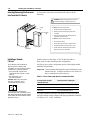
Installing Your ControlNet PLC-5 Processor
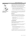
Handling the Processor
Wrist strap
19897
Compliance to European
Union Directives
1-3
<RXUSURFHVVRULVVKLSSHGLQDVWDWLFVKLHOGHGFRQWDLQHUWRJXDUG
DJDLQVWHOHFWURVWDWLFGDPDJH(OHFWURVWDWLFGLVFKDUJHFDQGDPDJH
LQWHJUDWHGFLUFXLWVRUVHPLFRQGXFWRUVLQWKHSURFHVVRULI\RXWRXFK
EDFNSODQHFRQQHFWRUSLQV,WFDQDOVRGDPDJHWKHPRGXOHZKHQ\RX
VHWFRQILJXUDWLRQSOXJVRUVZLWFKHVLQVLGHWKHPRGXOH$YRLG
HOHFWURVWDWLFGDPDJHE\REVHUYLQJWKHIROORZLQJSUHFDXWLRQV
5HPDLQLQFRQWDFWZLWKDQDSSURYHGJURXQGSRLQWZKLOHKDQGOLQJ
WKHPRGXOH²ZHDUDSURSHUO\JURXQGHGZULVWVWUDS
'RQRWWRXFKWKHEDFNSODQHFRQQHFWRURUFRQQHFWRUSLQV
:KHQQRWLQXVHNHHSWKHPRGXOHLQLWVVWDWLFVKLHOGHGFRQWDLQHU
If this product has the CE mark, it is approved for installation within
the European and EEA regions. It has been designed and tested to
meet the following directives.
EMC Directive
This product is tested to meet Council Directive 89/336/EEC
Electromagnetic Compatibility (EMC) and the following standards,
in whole or in part, documented in a technical construction file:
•
EN 50081-2 EMC — Generic Emission Standard, Part 2 —
Industrial Environment
•
EN 50082-2 EMC — Generic Immunity Standard, Part 2 —
Industrial Environment
Low Voltage Directive
This product is tested to meet Council Directive 73/23/EEC Low
Voltage by applying the safety requirements of EN 61131-2
Equipment Requirements and Tests.
For specific information required by EN 61131-2, see the appropriate
sections in this publication as well as the following Rockwell
Automation publications:
•
Industrial Automation Wiring and Grounding Guidelines For
Noise Immunity, publication 1770-4.1
•
Guidelines For Handling Lithium Batteries, publication AG-5.4
•
Automation Systems Catalog
This equipment is classified as open equipment and must be installed
(mounted) in an enclosure as a means of providing safety protection.
1785-6.5.22 - February 1999
1-4
Installing Your ControlNet PLC-5 Processor
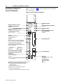
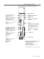
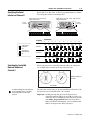
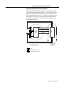
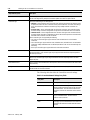
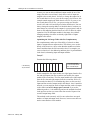
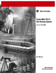
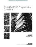
Identifying ControlNet PLC-5
Processor Components
)LJXUHDQG)LJXUHVKRZWKHIURQWSDQHOVRIWKH&RQWURO1HW
3/&SURFHVVRUV
Figure 1.1 PLC-5/20C Processor Front Panel
Battery Status Indicator
(Red)
Keyswitch-selects processor mode
ControlNet I/O Status Indicator
(Green/Red)
Channel 2 ControlNet Status Indicators
(Green/Red)
ControlNet Network Access Port
(NAP)-RJ45 connector
Processor RUN/FAULT Status Indicator
(Green/Red)
Force Status Indicator
(Amber)
Channel 0 Communication ACTIVE/
FAULT Status Indicator
(Green/Red)
Channel 2
ControlNet Redundant Media
Ports*BNC; dedicated
Channel 0
Serial Port-25-pin D-shell; supports standard EIA
RS-232C and RS-423; is RS-422A compatible 1
Memory Module Space
Use this port with ASCII or DF1 full-duplex,
half-duplex master, and half-duplex slave
protocols. The port’s default configuration supports
processor programming:
DF1 point-to-point
2400 bit/s
no parity
one stop-bit
BCC error check
no handshaking
Channel 1 Status Indicators (Green/Red)
Battery Compartment
DH+ Programming Terminal Connection
to Channel 1A
8-pin mini-DIN, parallel with 3-pin
connectors of Channel 1A
Channel 1A
3 pin; dedicated DH+
1 Channel 0 is optically coupled (provides high electrical
noise immunity) and can be used with most RS-422A
equipment as long as:
termination resistors are not used
the distance and transmission rate are reduced to
comply with RS-423 requirements
1785-6.5.22 - February 1999
Channel 1B
3 pin; default is remote I/O scanner;
configurable for:
remote I/O scanner
remote I/O adapter
DH+ communication
unused
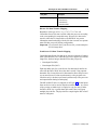
Installing Your ControlNet PLC-5 Processor
1-5
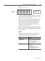
Figure 1.2 PLC-5/40C, -5/60C, and -5/80C Processors Front Panel
Battery Status Indicator
(Red)
Keyswitch-selects processor mode
ControlNet I/O Status Indicator
(Green/Red)
Channel 2 ControlNet Status Indicators
(Green/Red)
ControlNet Network Access Port
(NAP)-RJ45 connector
Channel 2
ControlNet Redundant Media Ports*
BNC; dedicated
Channel 1 Status Indicators (Green/Red)
DH+ Programming Terminal Connection
to Channel 1A
8-pin mini-DIN, parallel with 3-pin connectors
of Channel 1A; use only when Channel 1A is
configured for DH+ communications
Channel 1A
3 pin; default is DH+; configurable for:
remote I/O scanner
remote I/O adapter
DH+ communication
unused
Processor RUN/FAULT Status Indicator
(Green/Red)
Force Status Indicator
(Amber)
Channel 0 Communication ACTIVE/FAULT
Status Indicator
(Green/Red)
Channel 0
Serial Port-25-pin D-shell; supports standard EIA
RS-232C and RS-423; is RS-422A compatible 1
Use this port with ASCII or DF1 full-duplex,
half-duplex master, and half-duplex slave
protocols. The port’s default configuration supports
processor programming:
DF1 point-to-point
2400 bps
no parity
one stop-bit
BCC error check
no handshaking
Memory Module Space
Battery Compartment
Channel 1B
3 pin; default is remote I/O scanner;
configurable for:
remote I/O scanner
remote I/O adapter
DH+ communication
unused
1 Channel 0 is optically coupled (provides high
electrical noise immunity) and can be used with most
RS-422A equipment as long as:
termination resistors are not used
the distance and transmission rate are reduced to
comply with RS-423 requirements
1785-6.5.22 - February 1999
1-6
Installing Your ControlNet PLC-5 Processor
Setting the I/O Chassis
Backplane Switches
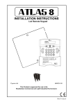
6HWWKH,2FKDVVLVEDFNSODQHVZLWFKHVXVLQJDEDOOSRLQWSHQWRVHW
HDFKVZLWFK
,PSRUWDQW'RQRWXVHDSHQFLOEHFDXVHWKHWLSFDQEUHDNRIIDQGVKRUW
WKHVZLWFK
Switch
Last State
1
O
N
O
F
F
ON
Outputs of this I/O chassis remain in their last state when a hardware
failure occurs.
OFF
Outputs of this I/O chassis are turned off when a hardware failure occurs. 1
1
2
Always OFF
3
4
Switches
5
Addressing
5
OFF
OFF
2 - slot
OFF
ON
1 - slot
ON
OFF
1/2 - slot
ON
ON
Not allowed
6
4
ON
OFF
7
8
Switches
EEPROM Transfer
6
7
OFF
OFF
EEPROM memory transfer to processor memory at powerup. 2 3
ON
ON
EEPROM memory transfers to processor memory if processor
memory not valid.
ON
OFF
EEPROM memory does not transfer to processor memory. 4
Switch
Processor Memory Protection
8
OFF
Processor memory protection disabled.
ON
Processor memory protection enabled. 5
1 Regardless of this switch setting, outputs are turned off when any of the following occurs:
processor detects a runtime error
an I/O chassis backplane fault occurs
you select Program or Test mode
you set a status file bit to reset a local rack
2 If an EEPROM module is not installed and processor memory is valid, the processor's
PROC indicator blinks and the processor sets bit S:11/9 in the major fault status word.
To clear this fault, change the processor from Program mode to Run mode and back to
Program mode.
3 If the processor's keyswitch is set in Remote, the processor enters Remote Run mode
after it powers up and has its memory updated by the EEPROM module.
4 A processor fault (solid red PROC LED) occurs if processor memory is not valid.
5 You cannot clear processor memory when this switch is on.
19309
1785-6.5.22 - February 1999
Installing Your ControlNet PLC-5 Processor
1-7
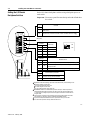
6HWWKH,2FKDVVLVFRQILJXUDWLRQSOXJDVIROORZV
Setting the I/O Chassis
Configuration Plug
Y N
1. Locate the chassis configuration plug
(between the two left most slots of
the chassis).
2. Set the I/O chassis configuration plug.
USING A
POWER-SUPPLY
MODULE IN
THE CHASSIS?
Y N
The default setting is N (not using a
power-supply module in the chassis).
Y N
Important: You cannot power a single I/O chassis
with both a power-supply module and an external
power supply.
Set Y when you install
a power-supply module
in the chassis.
Set N when you
use an external
power supply.
17075
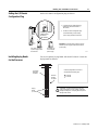
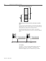
<RXUHFHLYHSODVWLFNH\LQJEDQGVZLWKHDFK,2FKDVVLV,QVHUWWKH
NH\LQJEDQGVDVIROORZV
Installing Keying Bands
for the Processor
I/O Chassis
Backplane
Connector
Keying
Bands
(1771-RK)
2
4
6
8
10
12
14
16
18
20
22
24
26
28
30
32
34
36
38
40
42
44
46
48
50
52
54
56
Install a keying band in the left-most
slot between the following pins:
40 and 42
54 and 56
Use these
numbers
as a guide.
!
ATTENTION: A module inserted into a wrong slot
could be damaged by improper voltages connected
through the wiring arm. Use keying bands to prevent
damage to the module.
12062
1785-6.5.22 - February 1999
1-8
Installing Your ControlNet PLC-5 Processor
Installing and Disposing of
the Processor Battery
E
MOR
7KH;<&EDWWHU\VKLSVZLWKWKHSURFHVVRUDQGUHTXLUHVVSHFLDO
KDQGOLQJ
)RUPRUHGHWDLOHGLQIRUPDWLRQDERXWLQVWDOOLQJDQGGLVSRVLQJRIWKH
EDWWHU\VHHWKH$OOHQ%UDGOH\*XLGHOLQHVIRU/LWKLXP%DWWHU\
+DQGOLQJDQG'LVSRVDOSXEOLFDWLRQ$*
$77(17,21 7RPDLQWDLQ&6$FHUWLILFDWLRQIRU
KD]DUGRXVDUHDVGRQRWVXEVWLWXWHDQ\RWKHUEDWWHU\IRU
WKH;<&
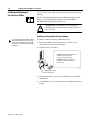
Installing or Removing the Processor Battery
You can insert or remove the battery without
powering down the processor. If you do not
want to lose your program, make sure that
the processor is powered on when removing
the battery.
7RLQVWDOORUUHPRYHWKHEDWWHU\IROORZWKHVHVWHSV
5HPRYHWKHWKXPEVFUHZRQWKHSURFHVVRU¶VEDWWHU\FRYHU
UHPRYHWKHFRYHUDQGORFDWHWKHEDWWHU\
,QVWDOORUUHPRYHWKHEDWWHU\
To install the battery, slide the battery-side
connector into the processor-side
connector until you hear them snap.
+
-
To remove the battery, press the lever on
the battery-side connector and slide the
connectors apart.
19331
Battery-side connector
Processor-side connector
5HSODFHWKHEDWWHU\FRYHUDQGVHFXUHWKHEDWWHU\FRYHUZLWKWKH
WKXPEVFUHZ
2QWKHEDWWHU\FRYHUZULWHWKHGDWHWKDW\RXLQVWDOOHGWKHODVWQHZ
EDWWHU\
1785-6.5.22 - February 1999
Installing Your ControlNet PLC-5 Processor
1-9
Replacing the Battery
You can insert or remove the battery without
powering down the processor. If you do not
want to lose your program, make sure that
the processor is powered on when replacing
the battery.
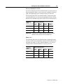
5HSODFHWKHOLWKLXPEDWWHU\HYHU\\HDURUZKHQWKH%$77VWDWXV
LQGLFDWRULVUHG)RUHVWLPDWHGEDWWHU\OLIHWLPHVVHHWKHWDEOHEHORZ
Worst-Case Battery-Life Estimates
Processor
Temperature
Power Off 100%
Power Off 50%
Battery Duration
60°C
173 days
346 days
70 hours
25°C
1.69 years
3.38 years
14.5 days
60°C
92.5 days
185 days
38 hours
25°C
1.25 years
2.5 years
10.8 days
60°C
80 days
160 days
33 hours
25°C
1.18 years
2.36 years
10 days
PLC-5/20C
PLC-5/40C
PLC-5/80C
The battery status indicator (BATT) warns you when the battery is low. These durations are based
on the battery supplying the only power to the processor—power to the chassis is off—once the
status indicator first lights.
Disposing of the Battery
'RQRWGLVSRVHRIOLWKLXPEDWWHULHVLQDJHQHUDOWUDVKFROOHFWLRQZKHQ
WKHLUFRPELQHGZHLJKWLVJUHDWHUWKDQRUHTXDOWRJUDP$VLQJOH
;<&EDWWHU\FRQWDLQVJUDPVRIOLWKLXP&KHFN\RXUVWDWH
DQGORFDOUHJXODWLRQVWKDWGHDOZLWKWKHGLVSRVDORIOLWKLXPEDWWHULHV
$77(17,21 )ROORZWKHVHSUHFDXWLRQV
'RQRWLQFLQHUDWHRUH[SRVHWKHEDWWHU\WRKLJK
WHPSHUDWXUHV
'RQRWVROGHUWKHEDWWHU\RUOHDGVWKHEDWWHU\
FRXOGH[SORGH
'RQRWRSHQSXQFWXUHRUFUXVKWKHEDWWHU\7KH
EDWWHU\FRXOGH[SORGHRUWR[LFFRUURVLYHDQG
IODPPDEOHFKHPLFDOVFRXOGEHH[SRVHG
'RQRWFKDUJHWKHEDWWHU\$QH[SORVLRQPD\
UHVXOWRUWKHFHOOPD\RYHUKHDWDQGFDXVHEXUQV
'RQRWVKRUWSRVLWLYHDQGQHJDWLYHWHUPLQDOV
WRJHWKHU7KHEDWWHU\ZLOOKHDWXS
1785-6.5.22 - February 1999
1-10
Installing Your ControlNet PLC-5 Processor
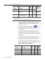
7RVHOHFWWKH'+VWDWLRQDGGUHVVRI&KDQQHO$VHWWKHVZLWFKHVRI
DVVHPEO\6:
Selecting the DH+ Station
Address of Channel 1A
Side View of PLC-5/20C, -5/40C, -5/60C, -5/80C Processor
Switch Assembly SW1
1
3
4
6
5
7
Toggle pushed
toward TOP
OFF
To select:
Set switch:
To:
DH+ Station Number
1 through 6
(See below)
Channel 1A DH+ Configuration
7
on (bottom)
off (top)
1
2
3
4
5
0
1
2
3
4
5
6
7
10
11
12
13
14
15
16
17
20
21
22
23
24
25
26
27
30
31
32
33
34
35
36
37
on
off
on
off
on
off
on
off
on
off
on
off
on
off
on
off
on
off
on
off
on
off
on
off
on
off
on
off
on
off
on
off
on
on
off
off
on
on
off
off
on
on
off
off
on
on
off
off
on
on
off
off
on
on
off
off
on
on
off
off
on
on
off
off
on
on
on
on
off
off
off
off
on
on
on
on
off
off
off
off
on
on
on
on
off
off
off
off
on
on
on
on
off
off
off
off
on
on
on
on
on
on
on
on
off
off
off
off
off
off
off
off
on
on
on
on
on
on
on
on
off
off
off
off
off
off
off
off
on
on
on
on
on
on
on
on
on
on
on
on
on
on
on
on
off
off
off
off
off
off
off
off
off
off
off
off
off
off
off
off
Toggle pushed
toward BOTTOM
ON
57.6 kbps
230.4 kbps
Switch
DH+
Station
Number
1785-6.5.22 - February 1999
2
Switch
6
DH+
Station
Number
1
2
3
4
5
6
on
on
on
on
on
on
on
on
on
on
on
on
on
on
on
on
on
on
on
on
on
on
on
on
on
on
on
on
on
on
on
on
40
41
42
43
44
45
46
47
50
51
52
53
54
55
56
57
60
61
62
63
64
65
66
67
70
71
72
73
74
75
76
77
on
off
on
off
on
off
on
off
on
off
on
off
on
off
on
off
on
off
on
off
on
off
on
off
on
off
on
off
on
off
on
off
on
on
off
off
on
on
off
off
on
on
off
off
on
on
off
off
on
on
off
off
on
on
off
off
on
on
off
off
on
on
off
off
on
on
on
on
off
off
off
off
on
on
on
on
off
off
off
off
on
on
on
on
off
off
off
off
on
on
on
on
off
off
off
off
on
on
on
on
on
on
on
on
off
off
off
off
off
off
off
off
on
on
on
on
on
on
on
on
off
off
off
off
off
off
off
off
on
on
on
on
on
on
on
on
on
on
on
on
on
on
on
on
off
off
off
off
off
off
off
off
off
off
off
off
off
off
off
off
off
off
off
off
off
off
off
off
off
off
off
off
off
off
off
off
off
off
off
off
off
off
off
off
off
off
off
off
off
off
off
off
Installing Your ControlNet PLC-5 Processor
1-11
6SHFLI\56&56$RU56FRPPXQLFDWLRQIRU&KDQQHO
E\VHWWLQJWKHVZLWFKHVRIDVVHPEO\6:
Specifying the Serial
Interface of Channel 0
Bottom View of PLC-5/20C Processor
Switch Assembly SW2
Bottom View of PLC-5/40C, -5/60C, -5/80C processor
Switch Assembly SW2
Front of
Processor
Front of
Processor
1
2
3
4
5
6
To Specify:
Toggle pushed
toward TOP
OFF
Toggle pushed
toward BOTTOM
ON
8
7
1
10
9
2
3
4
5
6
8
7
10
9
Set Switches:
1
2
3
4
5
6
7
8
9
10
ON
ON
ON
OFF
OFF
ON
ON
OFF
ON
OFF
OFF
OFF
ON
OFF
OFF
OFF
OFF
OFF
ON
OFF
ON
ON
ON
OFF
OFF
ON
OFF
OFF
ON
OFF
RS-232C
RS-422A
RS-423
Selecting the ControlNet
Network Address of
Channel 2
6HOHFW\RXUSURFHVVRU¶V&RQWURO1HWQHWZRUNDGGUHVVE\VHWWLQJWKH
WZRGLJLWURWDU\VZLWFKHVRQWKHWRSRIWKHSURFHVVRU
20
30
10
2
1
40
00
50
90
60
80
3
4
0
5
9
6
8
70
Network address 01
is shown
7
NET ADDRESS
For optimum throughput, assign addresses
to your ControlNet nodes in a sequential
order starting with 01 for the keeper
processor.
<RXFDQVHOHFWIURPDVPDQ\DVQHWZRUNDGGUHVVHVIURPWR
IRUDSURFHVVRURQD&RQWURO1HWOLQNLVLQYDOLG
,PSRUWDQW'RQRWSRZHUXSWKHSURFHVVRULIWKHSURFHVVRU¶V
&RQWURO1HWQHWZRUNDGGUHVVLVVHWWR,I\RXGR\RX
ZLOOQRWEHDEOHWRFRPPXQLFDWHZLWK\RXUSURFHVVRUDQG
\RXUODGGHUSURJUDPZLOOEHORVWHYHQLI\RXKDYHD
EDWWHU\LQVWDOOHG,IWKLVKDSSHQVVHOHFWDYDOLGQHWZRUN
DGGUHVVIRUWKHSURFHVVRUDQGF\FOHSRZHU
1785-6.5.22 - February 1999
1-12
Installing Your ControlNet PLC-5 Processor
Inserting/Removing the Processor
into/from the I/O Chassis
7RLQVHUWUHPRYHWKHSURFHVVRULQWRIURPWKHFKDVVLVGRWKH
IROORZLQJ
!
ATTENTION: Make certain that power to the chassis
is off before inserting or removing the processor.
To insert a processor into the chassis:
Locking
Bar
1. Lift the locking bar and the ejector tab.
Ejector
Tab
2. Slide the processor into the left-most slot of the
I/O chassis.
3. Press down on the ejector tab, and then close the
locking bar over the processor.
To remove a processor from the chassis:
1. Save processor memory.
2. Remove power to the processor-resident chassis.
3. Disconnect all cables from the processor's ports.
4. Lift the locking bar and the ejector tab, and then
slide the processor from the chassis.
Card Guides
19898
Installing a Remote
I/O Link
Trunk-cable/drop-cable considerations:
When using a trunk-cable/drop-cable
configuration, use 1770-SC station connectors
and follow these cable-length guidelines:
• trunk-cable length—depends on the
communication rate of the link; see Table
Table 1.A
• drop-cable length—30.4 m
(100 cable-ft) maximum
Important: When using a trunk-cable/
drop-cable configuration, set your
communication rate to 57.6K bit/s.
E
MOR
For more information about designing
trunk-cable/drop-cable configurations, see the
Data Highway/Data Highway Plus/Data Highway
II/Data Highway 485 Cable Installation Manual,
publication 1770-6.2.2.
1785-6.5.22 - February 1999
,QVWDOODUHPRWH,2OLQNXVLQJ&'FDEOHDQGHLWKHUD
GDLV\FKDLQRUWUXQNFDEOHGURSFDEOHFRQILJXUDWLRQ
9HULI\WKDW\RXUV\VWHP¶VGHVLJQSODQVVSHFLI\FDEOHOHQJWKVZLWKLQ
DOORZDEOHPHDVXUHPHQWV
,PSRUWDQW7KHPD[LPXPFDEOHOHQJWKIRUUHPRWH,2GHSHQGVRQWKH
WUDQVPLVVLRQUDWH&RQILJXUHDOOGHYLFHVRQDUHPRWH,2
OLQNWRFRPPXQLFDWHDWWKHVDPHUDWH
Table 1.A Correct Cable Length Based on Communication Rate
A remote I/O link using this
communication rate:
Cannot exceed this cable length:
57.6K bit/s
3,048 m (approximately 10,000 ft)
115.2K bit/s
1,524 m (approximately 5,000 ft)
230.4K bit/s
762 m (approximately 2,500 ft)
)RUSURSHURSHUDWLRQWHUPLQDWHERWKHQGVRIDUHPRWH,2OLQNE\
XVLQJWKHH[WHUQDOUHVLVWRUVVKLSSHGZLWKWKHSURJUDPPDEOHFRQWUROOHU
8VHHLWKHUDΩRUΩWHUPLQDWRU
Installing Your ControlNet PLC-5 Processor
1-13
The maximum number of
Use this
resistor
rating:
If your remote I/O link:
Operates at 230.4K bit/s
Operates at 57.6K or 115.2K bit/s, and no devices listed below are linked
Scanners
1771-SN; 1772-SD, -SD2;
82Ω
1775-SR, -S4A, -S4B;
6008-SQH1, -SQH2
Adapters
1771-AS; 1771-ASB (Series A Only); 1771-DCM
Miscellaneous
1771-AF
Connects to any device listed below:
Scanners
1771-SN; 1772-SD, -SD2;
1775-SR, -S4A, -S4B;
6008-SQH1, -SQH2
150Ω
Adapters
1771-AS; 1771-ASB (Series A Only); 1771-DCM
Miscellaneous
1771-AF
Operates at 57.6K or 115.2K bit/s, and you do not require over 16 physical devices
logical rack
physical devices
numbers that you
that you can connect can scan on the
on the link is:
link is:
32
16
16
16
You can install a remote I/O link two ways:
trunk cable / drop cable--from the drop cable to the connector screw terminals on the remote I/O connectors of the processor
daisy chain--to the connector screw terminals on the remote I/O connectors of the processor and then to the remote I/O screw
terminals of the next remote I/O device
To connect remote I/O cable:
1. Run the 1770-CD cable from the processor
to each remote I/O adapter module or
processor in the remote I/O system.
2. Connect the signal conductor with blue
insulation to the 3-pin connector terminal
labeled 1 on the processor and to each
remote I/O adapter module (or PLC-5
adapter) in the remote I/O system.
3. Connect the shield drain wire to the center
terminal of the 3-pin connector.
4. Connect the signal conductor with clear
insulation to the 3-pin connector terminal
labeled 2.
5. Tie wrap the remote I/O network cable to
the chassis to relieve strain on the cable.
6. Terminate the remote I/O link by connecting
an external terminator resistor between the
remote I/O terminals labeled 1 and 2.
PLC-5/40C, -5/60C,
-5/80C Processor
1770-CD
To another I/O
link device
Blue
Shield
Clear
Blue
Shield
Clear
PLC-5/20C
Processor
82W or
150W
resistor
1770-CD
Terminate both ends of a remote I/O link
1785-6.5.22 - February 1999
1-14
Installing Your ControlNet PLC-5 Processor
Installing a DH+ Link
8VH&'FDEOHWRFRQQHFWWKHSURFHVVRUWRD'+OLQN
)ROORZWKHVHJXLGHOLQHVZKLOHLQVWDOOLQJ'+FRPPXQLFDWLRQOLQNV
GRQRWH[FHHGWKHVHFDEOHOHQJWKV
±
WUXQNFDEOHOHQJWK²PDSSUR[LPDWHO\FDEOHIW
±
GURSFDEOHOHQJWK²PDSSUR[LPDWHO\FDEOHIW
GRQRWFRQQHFWPRUHWKDQVWDWLRQVRQDVLQJOH'+OLQN
Use the 3-pin connector on the processor to
connect a DH+ link. The connector’s port must
be configured to support a DH+
communication link.
You can install a DH+ link two ways:
trunk cable/drop cable-from the drop cable to
the connector screw terminals on the DH+
connectors of the processor
daisy chain-to the connector screw terminals
on the DH+ connectors of the processor
To make connections:
1. Connect the signal conductor with clear
insulation to the 3-pin connector terminal 1
at each end of each cable segment.
PLC-5/40C,
-5/60C, or -5/80C
Processor
2. Connect the shield drain wire to the center
terminal of the 3-pin connector at both ends
of each cable segment.
PLC-5/20C
Processor
3. Connect the signal conductor with blue
insulation to the 3-pin connector terminal 2
at each end of each cable segment.
Clear
Shield
Blue
Clear
Shield
Blue
MOR
E
For more information, see the Data Highway/Data
Highway Plus/Data Highway II/Data Highway 485
Cable Installation Manual, publication 1770-6.2.2.
1785-6.5.22 - February 1999
82W or 150W resistor
82W or 150W resistor
19339
Installing Your ControlNet PLC-5 Processor
1-15
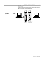
&RQQHFWD&RQWURO1HW3/&SURFHVVRUWRD&RQWURO1HWQHWZRUNYLDD
WDSZLWKDPLQGURSFDEOH
Connecting to a
ControlNet Network
)RXUWDSVDUHDYDLODEOHIURP5RFNZHOO$XWRPDWLRQ
Straight T-tap
Straight Y-tap
1786-TPS
Right-angle T-tap
Right-angle Y-tap
1786-TPR
1786-TPYS
1786-TPYR
,PSRUWDQW&RQWURO1HWWDSVFRQWDLQSDVVLYHHOHFWURQLFVDQGPXVWEH
SXUFKDVHGIURP5RFNZHOO$XWRPDWLRQIRUWKHQHWZRUNWR
IXQFWLRQSURSHUO\
$IWHUWHUPLQDWLQJ\RXUVHJPHQWV\RXFRQQHFW\RXUQRGHWRWKH
QHWZRUN
Remove the tap’s dust cap – located on the straight or
right-angle connector – and set it aside.
If your
network supports:
nonredundant media
redundant media
Connect the tap’s straight or
right-angle connector:
to the channel A connector on the
processor – channel B is not used
• from trunk-cable A to channel A
on the processor
and
• from trunk-cable B to channel B
on the processor
BATT
Nonredundant media
Redundant media
A
CH 0
A
CH 0
B
Rockwell Automation recommends using channel A for
nonredundant media.
E
MOR
)RUGHWDLOHGLQIRUPDWLRQDERXWSODQQLQJDQGLQVWDOOLQJ\RXU
&RQWURO1HWV\VWHPVHHWKHIROORZLQJSXEOLFDWLRQV
Publication
Publication Number
ControlNet Cable System Component List
AG-2.2
ControlNet Cable System Planning and Installation Manual
1786-6.2.1
ControlNet Coax Tap Installation Instructions
1786-2.3
ControlNet Network Access Cable Installation Instructions
1786-2.6
ControlNet Repeater Installation Instructions
1786-2.7
Industrial Automation Wiring and Grounding Guidelines
1770-4.1
1785-6.5.22 - February 1999
1-16
Installing Your ControlNet PLC-5 Processor
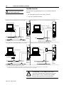
Connecting a
Programming Terminal
<RXFDQFRQQHFWDSURJUDPPLQJWHUPLQDOWRD&RQWURO1HW3/&
SURFHVVRUYLDD
'+FRQQHFWLRQ
VHULDOFKDQQHO
&RQWURO1HWFRQQHFWLRQ
DH+ Connection
7RDWWDFKDSURJUDPPLQJWHUPLQDOWRD&RQWURO1HW3/&SURFHVVRU
XVLQJD'+FRQQHFWLRQ
CH 0
Programming Terminal
DH+ Link
Programming Terminal
PLC-5/20C
Processor
When using this
communication card:
PLC-5/40C, -5/80C
Processor
Use this cable:
1784-KL, -KL/B
• 1784-CP6
• 1784-CP with 1784-CP7 adapter
• 1784-CP8 adapter
1784-KTK1
• 1784-CP5 with 1784-CP7 adapter
1784-KTx, KTxD
• 1784-CP13
1784-PCMK
• 1784-PCM6
• 1784-PCM5 with 1784-CP7 adapter
1784-KT, -KT2
1785-6.5.22 - February 1999
DH+ Link
Installing Your ControlNet PLC-5 Processor
1-17
Serial Channel
7RSURJUDPWKHSURFHVVRUXVLQJ&KDQQHOFRQILJXUHWKHFKDQQHOIRU
56&XVLQJ')SRLQWWRSRLQWSURWRFRO
If your programming
terminal has a:
9-pin serial port
25-pin serial port
Use cable:
1784-CP10
1784-CP11
Programming Terminal
Programming Terminal
PLC-5/20C
Processor
PLC-5/40C, -5/60C,
-5/80C Processor
1785-6.5.22 - February 1999
1-18
Installing Your ControlNet PLC-5 Processor
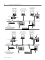
ControlNet Connection
!
ATTENTION: Do not connect the same
communication card to both the NAP and
a tap on the ControlNet network.
<RXFDQFRQQHFWSURJUDPPLQJGHYLFHVWRD&RQWURO1HWQHWZRUN
WKURXJK
WKH&RQWURO1HWQHWZRUNDFFHVVFDEOH&3
DWDSRQD&RQWURO1HWQHWZRUN
Using 1784-KTC15 or -KTCx15 or -PCC communication card and NAP*
Using 1784-KTCx15 communication card on coax media*
Programming Terminal
BATT
Programming Terminal
1784-KTC15 or -KTCx15
1786-CP**
or -PCC
1784-KTCx15
ControlNet network
ControlNet
PLC-5
Processor
Using 1770-KFC15 communication interface on coax media*
CH 0
ControlNet
PLC-5
Processor
ControlNet network
Using 1770-KFC15 communication interface and NAP*
Programming Terminal
Programming Terminal
1770-KFC15
Serial
Connection
Serial Connection
1786-CP**
BATT
CH 0
1770-KFC15
ControlNet network
ControlNet
PLC-5
Processor
ControlNet network
ControlNet
PLC-5
Processor
*Shown with redundant media (redundant media is not required).
**The network access cable (1786-CP) can be plugged into any ControlNet product’s NAP to provide programming capability on the ControlNet network.
A programming terminal connected through this cable is counted as a node and must have a unique address.
1785-6.5.22 - February 1999
$77(17,21 8VHWKH&3FDEOHZKHQ
FRQQHFWLQJDSURJUDPPLQJWHUPLQDOWRWKHQHWZRUN
WKURXJKD1$38VLQJDFRPPHUFLDOO\DYDLODEOH
5-VW\OHFDEOHFRXOGUHVXOWLQQHWZRUNIDLOXUH
Installing Your ControlNet PLC-5 Processor
Selecting Appropriate Cables
E
MOR
1-19
7KLVVHFWLRQOLVWVLQIRUPDWLRQDERXW
VHULDOFDEOHV
'+SURJUDPPLQJFDEOHV
UHPRWH,2FDEOHV
&RQWURO1HWFDEOHV
)RUPRUHLQIRUPDWLRQDERXWFDEOHVVHHWKH(QKDQFHGDQG(WKHUQHW
3/&3URJUDPPDEOH&RQWUROOHUV8VHU0DQXDOSXEOLFDWLRQ
Serial Cables
<RXFDQPDNH\RXURZQVHULDOFDEOHVRUSXUFKDVHWKHPIURP
5RFNZHOO$XWRPDWLRQ
7KHVLGHODEHORIWKHSURFHVVRUVKRZVWKHIROORZLQJWDEOHZKLFK
OLVWV&KDQQHOVHULDOSRUWSLQDVVLJQPHQWV
Pin
RS-232C
RS-422A
RS-423
Pin
RS-232C
RS-422A
RS-423
1
C.GND
C.GND
C.GND
14
NOT USED
TXD.OUT+
SEND COM
2
TXD.OUT
TXD.OUT-
TXD.OUT
15
3
RXD.IN
RXD.IN-
RXD.IN
16
NOT USED
RXD.IN+
REC COM
4
RTS.OUT
RTS.OUT+
RTS.OUT
17
5
CTS.IN
CTS.IN+
CTS.IN
18
6
DSR.IN
DSR.IN
DSR.IN
19
NOT USED
RTS.OUT-
NOT USED
7
SIG.GND
SIG.GND
SIG.GND
20
DTR.OUT
DTR.OUT
DTR.OUT
8
DCD.IN
DCD.IN
DCD.IN
21
22
NOT USED
DSR.IN
NOT USED
23
NOT USED
DTR.OUT
NOT USED
9
10
NOT USED
DCD.IN
NOT USED
11
24
12
25
13
NOT USED
CTS.IN-
NOT USED
The shading indicates that the pin is reserved.
7KLVSURFHVVRU¶VVHULDOSRUWFDQVXSSRUWWKHVHFRQILJXUDWLRQV
Digital Interface
Maximum Cable Length
RS-232C
15 m (approximately 50 ft)
RS-422A (compatible)
61 m (approximately 200 ft)
RS-423
61 m (approximately 200 ft)
1785-6.5.22 - February 1999
1-20
Installing Your ControlNet PLC-5 Processor
,PSRUWDQW)ROORZWKHVHJXLGHOLQHV
:KHQ&KDQQHOLVFRQILJXUHGIRU56$FRPSDWLELOLW\GRQRW
XVHWHUPLQDWLQJUHVLVWRUVDQ\ZKHUHRQWKHOLQN
:KHQ&KDQQHOLVFRQILJXUHGIRU56$FRPSDWLEOHDQG
56GRQRWJREH\RQGPDSSUR[LPDWHO\IW7KLV
GLVWDQFHUHVWULFWLRQLVLQGHSHQGHQWRIWKHWUDQVPLVVLRQUDWH
DH+ Programming Cables
When using this
communication card:
Use this cable:
1784-KL, -KL/B
• 1784-CP6
• 1784-CP with 1784-CP7 adapter
• 1784-CP8 adapter
1784-KTK1
• 1784-CP5 with 1784-CP7 adapter
1784-KTx, KTxD
• 1784-CP13
1784-PCMK
• 1784-PCM6
• 1784-PCM5 with 1784-CP7 adapter
1784-KT, -KT2
Remote I/O Cables
8VH&'RUFDEOHIRUUHPRWH,26HHSDJHIRUPRUH
LQIRUPDWLRQ
ControlNet Cables
6HYHUDOW\SHVRI5*TXDGVKLHOGFDEOHPD\EHDSSURSULDWHIRU\RXU
&RQWURO1HWLQVWDOODWLRQ²GHSHQGLQJRQWKHHQYLURQPHQWDOIDFWRUV
DVVRFLDWHGZLWK\RXUDSSOLFDWLRQDQGLQVWDOODWLRQVLWH
1785-6.5.22 - February 1999
Installing Your ControlNet PLC-5 Processor
1-21
7KHIROORZLQJ&RQWURO1HWFDEOHV\VWHPFRPSRQHQWVDUHDYDLODEOH
IURPWKH5RFNZHOO$XWRPDWLRQ
Item1
Cat. No.
ControlNet Coax Tool Kit
1786-CTK
Coax Tap Kit
Right-angle T-tap
1786-TPR
Straight T-tap
1786-TPS
Right-angle Y-tap
1786-TPYR
Straight Y-tap
1786-TPYS
High-voltage ac & dc
1786-RPT
Low-voltage dc
1786-RPTD
Fiberoptic Repeaters
Low-voltage dc
1786-RPA
RG-6 Quad Shield Cable
Standard-PVC CM-CL2
1786-RG6
Repeaters
ControlNet Network Access Cable—3.05 m (10 ft)
1786-CP
BNC Connectors
Barrel (plug to plug)
1786-BNCP
BNC/RG-6 plug
1786-BNC
Bullet (jack to jack)
1786-BNCJ
Isolated-bulkhead (jack to
jack)
1786-BNCJI
Terminators (BNC-75Ω)
1786-XT
For a complete list of ControlNet cable system components that are available
from Rockwell Automation and other sources, see the ControlNet Cable System
Component List, publication AG-2.2.
,PSRUWDQW,QVWDOODOOZLULQJIRU\RXU&RQWURO1HWV\VWHPLQ
DFFRUGDQFHZLWKWKHUHJXODWLRQVFRQWDLQHGLQWKH
1DWLRQDO(OHFWULF&RGHRUDSSOLFDEOHFRXQWU\FRGHV
VWDWHFRGHVDQGDSSOLFDEOHPXQLFLSDOFRGHV
1785-6.5.22 - February 1999
1-22
Installing Your ControlNet PLC-5 Processor
E
MOR
)RUGHWDLOHGLQIRUPDWLRQDERXW&RQWURO1HWFDEOLQJVHHWKHIROORZLQJ
SXEOLFDWLRQV
Publication
1785-6.5.22 - February 1999
Publication
Number
ControlNet Cable System Component List
AG-2.2
ControlNet Cable System Planning and Installation Manual
1786-6.2.1
ControlNet Coax Tap Installation Instructions
1786-2.3
ControlNet Network Access Cable Installation Instructions
1786-2.6
ControlNet Repeater Installation Instructions
1786-2.7
ControlNet System Overview
1786-2.9
Industrial Automation Wiring and Grounding Guidelines
1770-4.1
Chapter
2
Planning to Use Your ControlNet PLC-5
Processor
Using This Chapter
If you want to read about:
Go to page:
Understanding ControlNet I/O
2-1
Understanding ControlNet I/O mapping
2-8
Using I/O Mapping Techniques
2-21
Using the ControlNet PLC-5 processor in a ControlNet I/O system
2-31
Converting from a remote I/O system to a ControlNet I/O system
2-34
Converting from ControlNet phase 1.0 or 1.25 to ControlNet
phase 1.5
2-34
7RGLVWLQJXLVKSKDVH&RQWURO1HWSURFHVVRUVIURPHDUOLHUSKDVH
SURFHVVRUVQHZFDWDORJQXPEHUVZHUHFUHDWHGIRUHDFKRIWKHSKDVH
&RQWURO1HWSURFHVVRUV/&/&DQG
/&
Understanding
ControlNet I/O
$77(17,21 <RXFDQQRWPL[DQGHDUOLHUSKDVH
SURGXFWVRQWKHVDPH&RQWURO1HWQHWZRUN
7KH&RQWURO1HWV\VWHPLVGHVLJQHGWR
SURYLGHKLJKVSHHGUHSHDWDEOHGHWHUPLQLVWLF,2WUDQVPLVVLRQ
DOORZFRQWURODQGPHVVDJHLQIRUPDWLRQWRFRH[LVWRQWKHVDPH
SK\VLFDOPHGLD
PDNHVXUHWKDW,2GDWDWUDQVIHUVDUHQRWDIIHFWHGE\
SURJUDPPLQJWHUPLQDOPHVVDJHDFWLYLW\
LQWHU3/&SURFHVVRUPHVVDJHDFWLYLW\RQWKHQHWZRUN
1785-6.5.22 - February 1999
2-2
Planning to Use Your ControlNet PLC-5 Processor
Scheduled Data-Transfer Operations on a ControlNet Network
&RQWURO1HWVFKHGXOHGGDWDWUDQVIHURQD&RQWURO1HW3/&SURFHVVRU
LVFRQWLQXRXV
LVDV\QFKURQRXVWRWKHODGGHUORJLFSURJUDPVFDQ
RFFXUVDWWKHDFWXDOUDWHGLVSOD\HGLQWKH$FWXDO3DFNHW,QWHUYDO
ILHOGRQWKHSURJUDPPLQJVRIWZDUH&RQWURO1HW,2PDSSLQJ
PRQLWRUVFUHHQ
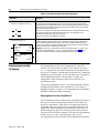
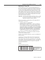
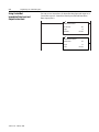
,QVFKHGXOHGGLVFUHWH,2GDWDWUDQVIHUIRUH[DPSOHWKHIROORZLQJ
XSGDWHVRFFXUEHWZHHQORJLFVFDQVLHGXULQJ³KRXVHNHHSLQJ´
WKHLQSXWLPDJHLVPRYHGIURPDSULYDWHPHPRU\EXIIHUWRWKH
SURFHVVRU¶VLQSXWLPDJHILOHIRUXVHGXULQJWKHQH[WORJLFVFDQ
WKHGDWDIURPWKHRXWSXWLPDJHILOHLVSXWLQWRDSULYDWHPHPRU\
EXIIHUDQGLVVHQWGXULQJWKHQH[WVFKHGXOHGFRPPXQLFDWLRQF\FOH
Private
Memory
Buffers
Scheduled Data Transfer
1785-6.5.22 - February 1999
DataTable
Files
Data Update
Logic Scan
Housekeeping
Scheduled Data Transfers
$VLPLODUPHWKRGLVXVHGIRUDOOVFKHGXOHGGDWDWUDQVIHURSHUDWLRQV
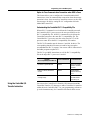
Program Scan
Planning to Use Your ControlNet PLC-5 Processor
2-3
7KHIROORZLQJVFKHGXOHGGDWDWUDQVIHURSHUDWLRQVDUHVXSSRUWHGE\WKH
&RQWURO1HWSURFHVVRUVRQD&RQWURO1HWQHWZRUN
Table 2.A ControlNet Scheduled Data-Transfer Operations
Operation
Description
Discrete I/O Data
Transfer
Performed in a deterministic and repeatable manner
asynchronous to and independent of the ladder-logic
program scan. You configure all ControlNet discrete I/O
data transfers on a per-node basis in the I/O map
table.
Non-discrete I/O Data
Transfer
Handled with the same priority as discrete I/O data
transfer. You can update analog data without using
block-transfer instructions in ladder programs. You do
this by including non-discrete I/O data-transfer
configurations in the I/O map table. This data is
updated in the buffers and data-table files between
logic scans in the same manner as that used in
discrete I/O data transfer.
Peer-to-peer
Communication
Allows a ControlNet processor to communicate with
any other ControlNet processor on the ControlNet
network with the same priority as that of the discrete
and non-discrete I/O data transfers discussed above.¢
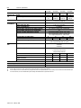
While scheduled data transfer is asynchronous to program scanning, all data is
presented synchronously to the processor and output buffers during housekeeping.
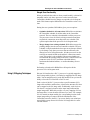
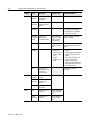
Unscheduled Data-Transfer Operations on a ControlNet Network
7KH&RQWURO1HWQHWZRUNDOORZV\RXWRXVHXQVFKHGXOHGPHVVDJLQJ
ZKHQGHWHUPLQLVWLFGHOLYHU\LVQRWUHTXLUHG8QVFKHGXOHGRSHUDWLRQV
LQFOXGH
XQVFKHGXOHGQRQGLVFUHWH,2GDWDWUDQVIHUV²WKURXJK&RQWURO1HW
,27UDQVIHU&,2LQVWUXFWLRQV
SHHUWRSHHUPHVVDJLQJ²WKURXJK0HVVDJH06*LQVWUXFWLRQV
PHVVDJLQJIURPSURJUDPPLQJGHYLFHV
1785-6.5.22 - February 1999
2-4
Planning to Use Your ControlNet PLC-5 Processor
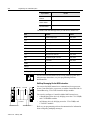
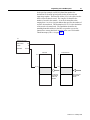
7KH&RQWURO1HWV\VWHPSODFHV\RXUVFKHGXOHGWUDQVIHUVLQWKHILUVW
SDUWRIHDFK1HWZRUN8SGDWH,QWHUYDO18,7LPHLVDXWRPDWLFDOO\
UHVHUYHGIRUQHWZRUNPDLQWHQDQFH8QVFKHGXOHGWUDQVIHUVDUH
SHUIRUPHGGXULQJWKHWLPHUHPDLQLQJLQWKHLQWHUYDO
One occurrence of the NUT is a NUI
You reserve a
specific amount
of time for all
scheduled
operations
. . .
The system
reserves time
for network
maintenance
Any time remaining is used
for unscheduled operations
. . .
8QVFKHGXOHGPHVVDJLQJRQD&RQWURO1HWQHWZRUNLV
QRQGHWHUPLQLVWLF<RXUDSSOLFDWLRQDQG\RXUFRQILJXUDWLRQ²QXPEHU
RIQRGHVDSSOLFDWLRQSURJUDP187DPRXQWRIVFKHGXOHGEDQGZLGWK
XVHGHWF²GHWHUPLQHKRZPXFKWLPHWKHUHLVIRUXQVFKHGXOHG
PHVVDJLQJ
,PSRUWDQW7KH&RQWURO1HWQHWZRUNUHVHUYHVWLPHIRUDWOHDVWRQH
PD[LPXPVL]HGXQVFKHGXOHGWUDQVIHUSHU18,
'HSHQGLQJRQKRZPXFKWLPHWKHUHLVIRUXQVFKHGXOHG
PHVVDJLQJHYHU\QRGHPD\QRWKDYHDFKDQFHWRVHQG
XQVFKHGXOHGGDWDHYHU\18,
1785-6.5.22 - February 1999
Planning to Use Your ControlNet PLC-5 Processor
2-5
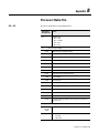
Table 2.B ControlNet Unscheduled Data-Transfer Operations
Operation
Description
Features
Non-discrete I/O
Data Transfer
Perform ladder-initiated unscheduled non-discrete I/O data transfers on
a ControlNet network by using ControlNet I/O Transfer (CIO) instructions.
The data type for these transfers (CT) has the following information:
• Command:
1771 READ
reads data from a 1771 non-discrete
I/O module
1771 WRITE
writes data to a 1771 non-discrete
I/O module
1794 READ
reads data from a 1794 I/O module
1794 WRITE
writes data to a 1794 I/O module
1794 FAULT ACTION
changes the action a module takes
when it faults
1794 IDLE ACTION
changes the action a module takes
when it is idle
1794 CONFIG DATA
changes a module’s configuration data
1794 SAFE STATE DATA
changes a module’s safe-state data
CIP GENERIC
sends user-specified CIP service
• Data-table address in source processor
• Size of message in words
• Network address of destination node
• Slot of destination module
• Port number—set to 2 for the ControlNet network
• Flags:
.TO forces a transfer to time out
.EW indicates that the transfer is waiting for an open connection
.CO transfer is made continuously in Run mode
.ER indicates that the transfer was terminated due to an error
.DN indicates that the transfer was made without error
.ST indicates that the transfer was started
.EN indicates that the transfer instruction is enabled
• As many as 32 1771 READ and/or 1771 WRITE
CIOs can be active at a time • Minor fault bit S:17/14 is set when 32 1771
READ and/or 1771 WRITE CIOs are active at a
time
• As many as 8 1794 Flex I/O CIOs can be active
at a time • Minor fault bit S:17/15 is set when 8 1794 Flex
I/O CIOs are active at a time
• Any transfer initiated from a Processor Input
Interrupt (PII) or Selectable Timed Interrupt (STI)
program suspends execution of the program
scan until the transfer is completed
Important: This can extend your program scan
by tens of milliseconds.
• No transfer is initiated when the processor is in
Program mode
• Transfers that have been running with the .CO
bit set automatically restart on the
Program-to-Run transition when the Continue
Last step bit is set and the data table has not
changed
• A transfer has a maximum size of 64 words
• As long as an adapter is owned by a processor,
any processor within the ControlNet network
can send or receive transfers to or from any of
that adapter’s modules
• If the SFC startover bit is set in the processor
configuration file, continuous CIOs may time out
if you cycle power in RUN mode. If this happens,
the CIO error bit is set. To reset the error bit, the
CIO instruction rung condition must go from
FALSE to TRUE.
See pages 4-3 and C-1 for more information.
CIO Instructions
• Error code—indicates the error when the .ER bit is set • Done length—indicates the number of words transferred
1785-6.5.22 - February 1999
2-6
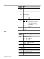
Planning to Use Your ControlNet PLC-5 Processor
Operation
Description
Features
Peer-to-peer
Messaging
You can use ControlNet message (MSG) instructions and the data-type
MG to create unscheduled messages that are initiated by one ControlNet
PLC-5 processor and sent to another ControlNet PLC-5 processor. The
MG data type for the ControlNet instruction has the following
information:
• Command—PLC-5 TYPED READ, PLC-5 TYPED WRITE, PLC-3 WORD
RANGE READ, PLC-3 WORD RANGE WRITE, PLC-2 UNPROTECTED
READ, PLC-2 UNPROTECTED WRITE
• Data-table address in source processor
• Size of message in elements
• Network address of destination processor
• Data-table address in destination processor
• Port number—set to 2 for the ControlNet network
• Flags:
.TO forces a message to time out
.EW indicates that the message is waiting for an open connection
.CO message is sent continuously in Run mode
.ER indicates that the message was terminated due to an error
.DN indicates that the message was sent without error
.ST indicates that the message was started
.EN indicates that the message instruction is enabled
.NC forces the connection to close when the message is done
• As many as 32 ControlNet MSGs can be active
at a time • Minor fault bit S:17/13 is set when 32
ControlNet MSGs are active at a time
• All messages have the same priority
• No message is initiated when the processor is
in Program mode
• Messages that have been running with the .CO
bit set automatically restart on the Programto-Run transition when the Continue Last step
bit is set and the data table has not changed
• Each message has a maximum size of 1000
elements
See pages 4-1 and C-1 for more information.
MSG Instructions
• Error code—indicates the error when the .ER bit is set Because connections are opened and closed as needed, more can exist in a program as long as no more than this number are active at one time.
See Appendix D for a list of ControlNet error codes.
Using I/O Forcing Operations
&RQWURO1HW,2IRUFLQJRFFXUVLQWKHVDPHZD\DVUHPRWH,2IRUFLQJ
LQWKH&RQWURO1HWSURFHVVRUV7KHSURFHVVRUSHUIRUPVWKHIRUFLQJDQG
WUDQVPLWVWKHIRUFHGGDWDWRWKHRXWSXWDQGLQSXWLPDJHWDEOHV<RX
FDQIRUFHDQ\GLVFUHWH,2GDWDSODFHGLQWKH,2LPDJHKRZHYHU
IRUFLQJRIQRQGLVFUHWH,2GDWDLVQRWVXSSRUWHG
)RUGHWDLOHGLQIRUPDWLRQDERXWIRUFLQJVHH\RXUSURJUDPPLQJ
VRIWZDUHGRFXPHQWDWLRQ
1785-6.5.22 - February 1999
Planning to Use Your ControlNet PLC-5 Processor
2-7
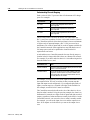
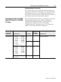
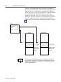
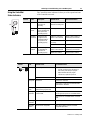
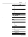
Using Immediate Data-Transfer Operations
&RQWURO1HW,PPHGLDWH'DWD,2WUDQVIHUV²,PPHGLDWH'DWD,QSXW
,',DQG,PPHGLDWH'DWD2XWSXW,'2²SHUIRUPVLPLODUO\WRWKH
5HPRWH,2VXSSRUWHGLPPHGLDWH,2WUDQVIHUV²,PPHGLDWH,QSXW
,,1DQG,PPHGLDWH2XWSXW,27²ZKLFKWKH&RQWURO1HWV\VWHP
DOVRVXSSRUWV7KHORJLFVFDQLVWHPSRUDULO\LQWHUUXSWHGZKLOHWKH
PRVWUHFHQWVWDWHRIXSWRZRUGVLVUHDGIURPRUZULWWHQWRWKH
SULYDWHPHPRU\EXIIHU
Immediate Data Transfer
DataTable
Files
Data Update
ControlNet Data Transfer
Logic Scan
Housekeeping
Private
Memory
Buffers
Program Scan
= NUI
= Scheduled Data Transfer
= Unscheduled Data Transfer
1785-6.5.22 - February 1999
2-8
Planning to Use Your ControlNet PLC-5 Processor
Table 2.C ControlNet Immediate Data-Transfer Operations
Instructions
Immediate I/O-ControlNet and Remote I/O
001
( IIN )
001
( IOT )
ControlNet Immediate Data I/O
IDI
IMMEDIATE DATA INPUT
Data file offset
232
Length
10
Destination
N11:232
IDO
IMMEDIATE DATA OUTPUT
Data file offset
175
Length
24
Source
N12:175
Understanding ControlNet
I/O Mapping
Description
In the case of an IIN, the most recent copy of the specified input word secured in the last discrete I/O
data transfer from the corresponding I/O chassis is used. This value is moved from the private
memory buffer to the working data table and is used in all subsequent ladder instructions. This data
could be as old as the time taken since the last asynchronous I/O update, and it may not actually
reflect the latest state of the input word.
In the case of an IOT, the current state of the specified output word is copied to the private memory
buffer and is used on the next output update to the I/O chassis. The actual change is not
communicated until the next asynchronous I/O transfer.
Only 1 word of I/O data can be updated per instruction.
The ControlNet Immediate Data I/O instructions work in much the same way as the immediate I/O
instructions. During an input instruction, the most recent data is copied from the private memory
buffer to a data-table address that you specify. In the case of an output instruction, the data is
copied from an area that you specify to the private memory buffer and sent on the next I/O update.
As many as 64 words can be transferred per instruction.
Important: In most cases, you should set the Data file offset and the Source—of an IDO—or the
Data file offset and the Destination—of an IDI—to the same address. See page 4-5 for more
information on this and other aspects of using ControlNet IDI and IDO instructions.
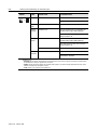
$OOVFKHGXOHGGDWDWUDQVIHUVPXVWEHPDSSHGRQD&RQWURO1HW
QHWZRUN<RXVSHFLI\ZKHUH,2GDWDLVWREHUHDGIURPRUZULWWHQ
WR²LHPDSSHG<RXGRWKLVDQGHVWDEOLVKWKHUHODWLRQVKLSEHWZHHQ
SURFHVVRUV,2DGDSWHUVDQGGDWDWDEOHILOHDGGUHVVHVE\FUHDWLQJDQG
PDLQWDLQLQJDQ,2PDSWDEOH$Q,2PDSWDEOHHQWU\LVUHTXLUHGIRU
HDFKVFKHGXOHGGDWDWUDQVIHU7KHPDSWDEOHLVVWRUHGLQWKH
FRQILJXUDWLRQVHFWLRQRIPHPRU\DQGLVQRWDFFHVVLEOHE\\RXU
DSSOLFDWLRQSURJUDP
8VLQJ\RXUSURJUDPPLQJVRIWZDUH\RXFDQDXWRPDWLFDOO\FRQILJXUH
DQGPDSQRGHVDWWDFKHGWR\RXU&RQWURO1HW,26HH8VLQJ,2
0DSSLQJ7HFKQLTXHVRQSDJHIRULQIRUPDWLRQDERXW&RQWURO1HW
DXWRPDWLFFRQILJXUDWLRQDQG,2PDSSLQJ
Reserving Space for Non-ControlNet I/O
1RQ&RQWURO1HWSURFHVVRUUHVLGHQWORFDO,2DQG5HPRWH,2GHYLFHV
FDQRQO\XVHIL[HG,2LPDJHORFDWLRQVEDVHGRQUDFNQXPEHUIRU
GLVFUHWH,2GDWDWUDQVIHUZKLOHGLVFUHWH,2GDWDWUDQVIHUEHWZHHQ
&RQWURO1HWQRGHVFDQEHPDSSHGWRDQ\XQXVHGORFDWLRQLQWKH,2
LPDJHWDEOHV%HIRUHPDSSLQJ\RXU&RQWURO1HW,2WKHUHIRUH\RX
VKRXOGFRQILJXUHDQ\SURFHVVRUUHVLGHQWORFDO,2DQGDQ\5HPRWH
,2UDFNVRQQRQ&RQWURO1HWFKDQQHOV7KLVDOORZVWKHSURJUDPPLQJ
VRIWZDUHWRUHVHUYHLQSXWDQGRXWSXWLPDJHVSDFHIRUDOO
QRQ&RQWURO1HWSURFHVVRUUHVLGHQWORFDO,2DQG5HPRWH,2FKDVVLV
1785-6.5.22 - February 1999
Planning to Use Your ControlNet PLC-5 Processor
2-9
3URFHVVRU5HVLGHQW/RFDO,2
,I\RXILUVWFRQILJXUHSURFHVVRUUHVLGHQWORFDO,2RQ\RXUSURFHVVRU
WKHSURJUDPPLQJVRIWZDUHUHVHUYHVSURFHVVRUUHVLGHQWORFDOFKDVVLV
LQSXWDQGRXWSXWLPDJHVSDFHVWDUWLQJDWRIIVHWLQERWKILOHV
7KHIROORZLQJWDEOHVKRZVWKHGHIDXOWQXPEHURILQSXWDQGRXWSXW
ZRUGVDXWRPDWLFDOO\UHVHUYHGE\WKHSURJUDPPLQJVRIWZDUHIRUWKH
GLIIHUHQWVL]HVDQGDGGUHVVLQJPRGHVRISURFHVVRUUHVLGHQWORFDO,2
Addressing
Mode
Number of Words Reserved
4 Slots
8 Slots
12 Slots
16 Slots
2 Slot
8
8
8
8
1 Slot
8
8
16
16
1/2 Slot
8
16
24
32
,PSRUWDQW&RQWURO1HW,2FDQQRWPDSLQWRDQ\SDUWRIDUDFN
QXPEHUXVHGE\WKHSURFHVVRUUHVLGHQWUDFN
5HPRWH,2
7KHIROORZLQJWDEOHVKRZVWKHGHIDXOWQXPEHURILQSXWDQGRXWSXW
ZRUGVUHVHUYHGE\WKHSURJUDPPLQJVRIWZDUHIRUWKHGLIIHUHQWVL]HV
DQGDGGUHVVLQJPRGHVRIQRQ&RQWURO1HW5HPRWH,2LI\RXILUVW
FRQILJXUHQRQ&RQWURO1HW5HPRWH,2RQ\RXUSURFHVVRU
Addressing
Mode
Number of Words Reserved
4 Slots
8 Slots
12 Slots
16 Slots
2 Slot
2
4
6
8
1 Slot
4
8
12
16
1/2 Slot
8
16
24
32
1785-6.5.22 - February 1999
2-10
Planning to Use Your ControlNet PLC-5 Processor
7KHSURJUDPPLQJVRIWZDUHUHVHUYHVQRQ&RQWURO1HW5HPRWH,2
RXWSXWDQGLQSXWLPDJHVSDFHDFFRUGLQJWRWKHVHJXLGHOLQHV
,WGRHVQRWRYHUODSSURFHVVRUUHVLGHQWORFDO,2UHVHUYHGLPDJH
VSDFH
,WDGGUHVVHVLQSXWDQGRXWSXWLPDJHVSDFHRIIVHWLQRFWDOIURP
±
²IRUWKH3/&&SURFHVVRU
±
²IRUWKH3/&&SURFHVVRU
±
²IRUWKH3/&&SURFHVVRU
7KHRXWSXWLPDJHRIIVHWYDOXHLQWKH,2PDSFRUUHVSRQGVWRWKH
ILUVWVORWRIWKHUHIHUHQFHGFKDVVLV²LHLQDVORWFKDVVLVVHWIRU
VORWDGGUHVVLQJWKHFRUUHVSRQGLQJRXWSXWLPDJHRIIVHWRI2
ZRXOGPDSWKHZRUGV222DQG2WRVORWV
DQGUHVSHFWLYHO\
7KHLQSXWLPDJHRIIVHWFRUUHVSRQGVWRWKHILUVWVORWLQWKH
UHIHUHQFHGUDFNDQGWKHRIIVHWORFDWLRQRIWKHLQSXWPRGXOHVLQ
WKDWUDFNFRUUHVSRQGVWRWKHVDPHRIIVHWLQWKHLPDJHWDEOH²LH
LIDFKDVVLVVHWIRUVORWDGGUHVVLQJKDVDQLQSXWLPDJHRIIVHWRI
,DQGDQLQSXWPRGXOHLQVORWWKHZRUGWKDWFRUUHVSRQGVWR
WKDWLQSXWPRGXOHZRXOGEH,RU,
Mapping ControlNet Data Transfer
7KHIROORZLQJWDEOHVKRZVWKHPD[LPXP,2PDSHQWULHVDOORZHGLQ
WKH&RQWURO1HW,2PDSWDEOH
Table 2.D Maximum I/O Map Entries
Number of
Mappings:
Processor:
Number of DIF
Files:
Number of DIF
Words:
Number of DOF
Files:
Number of DOF
Words:
PLC-5/20C
64
2
2000
2
2000
PLC-5/40C
96
3
3000
3
3000
PLC-5/80C
128
4
4000
4
4000
1785-6.5.22 - February 1999
Planning to Use Your ControlNet PLC-5 Processor
2-11
(DFKPDSWDEOHHQWU\FRUUHVSRQGVWRRQHWUDQVIHU²LQSXWRQO\RXWSXW
RQO\RUERWKLQSXWDQGRXWSXW²RIGDWDEHWZHHQWKH&RQWURO1HW
SURFHVVRUDQGDQ,2UDFNDQ,2PRGXOHRUDQRWKHU&RQWURO1HW
SURFHVVRU
Table 2.E Files That You Configure with the I/O Map for Scheduled I/O Usage
File
Description
ControlNet Status File
User-specified integer data table file containing status information about this processor’s scheduled I/O
map-table entries. Each I/O map table entry has a status-file offset field pointing to three status words
associated with that entry. Refer to Appendix D for more information on I/O map-table entry status words.
ControlNet Diagnostics File
User-specified integer data table file containing diagnostics about the ControlNet network (not required).
See Appendix F.
Data Input File (DIF)
User-specified integer data-table file with a maximum of:
• 2000 words for the PLC-5/20C processor (spanning two contiguous data table files)
• 3000 words for the PLC-5/40C processor (spanning three contiguous data table files)
• 4000 words for the PLC-5/80C processor (spanning four contiguous data table files)
This file is typically used for non-discrete input data and peer-to-peer input. Discrete input data may be
mapped to DIF as well.
Data Output File (DOF)
User-specified integer data-table file with a maximum of:
• 2000 words for the PLC-5/20C processor (spanning two contiguous data table files)
• 3000 words for the PLC-5/40C processor (spanning three contiguous data table files)
• 4000 words for the PLC-5/80C processor (spanning four contiguous data table files)
This file is typically used for non-discrete output data and peer-to-peer output. Discrete output data may
be mapped to DOF as well.
Configuration File
User-specified integer data-table file used to store non-discrete I/O data transfer configuration data. This
configuration data is sent to the target device each time the connection is opened.
Table 2.F ControlNet I/O Map-Table Entry Fields
Map-Table Entry Field
Description
Node
This is the node’s ControlNet network address.
Slot/Symbol/Message Numbers
The slot/message value takes on different meanings with the different communication options:
• 1747, 1771 and 1794 discrete I/O data transfer—the slot value does not apply because the mapping
granularity is based on the physical chassis
• 1747 non-discrete I/O data transfer — 0-29, the slot number is always the physical slot location inside
the 1746 chassis
• 1771 non-discrete I/O data transfer—0-15, the slot number is always the physical slot location inside
the 1771 chassis regardless of addressing mode within the chassis
• 1794 non-discrete I/O data transfer—0-7, the slot number is always the physical location in the 1794
rack
• peer-to-peer communication—1 to the maximum number of I/O map entries (see Table 2.D on page
2-10), the message number must be the same for both processors involved
Module/Message Type
This allows you to specify the module type or peer-to-peer message type—Receive Data From or Send
Data—in offline and online programming. It also determines how the map-table entries are configured
for the different modules and peer-to-peer messages.
Requested Packet Interval (RPI)
Set this to the maximum time allowed for the network to update the requested data. This value must be
at least as large as the network update time (NUT).
1785-6.5.22 - February 1999
2-12
Planning to Use Your ControlNet PLC-5 Processor
Map-Table Entry Field
Description
Actual Packet Interval (API)
This read-only field displays the actual time it takes for the network to update the requested data.
The API is the largest binary multiple of the Network Update Time smaller or equal to the RPI.
Connection Type
This is the connection type. The valid types are:
• multicast—where at least one owner connection must configure a device before any listeners can be
accepted, and at least one owner connection must be present at all times. If all owner connections go
away, communication to all multicast connections go away. Multiple multicast connections are
allowed.
• exclusive owner—where configuration data from all owners must agree. New connections that do
not match existing connection’s configuration are rejected. A second exclusive owner is not allowed.
• redundant owner—where configuration data from all owners must agree. New connections that do
not match existing connection’s configuration are rejected. An exclusive output owner connection after
redundant owner connections exist are not allowed.
These connection types are supported by the following:
• 1747 and 1771 connection types support exclusive owner and multicast for rack and module
connections.
• 1794 connection types support exclusive owner, redundant owner, and multicast for rack and module
connections. Multiple redundant owners are allowed (each device in the rack can be owned only once
exclusively).
• Peer-to-peer connection types support multicast for receive data connections.
Input Address and Size
This is the offset in the input file where the data is to be stored and the number of words to be received
from the input device. Any connection type may be mapped to either the discrete input image table or
the Data Input File (DIF).
Output Address and Size
This is the offset in the output file where the data is located and the number of words of the output
transfer. Any connection type may be mapped to either the discrete output image table or the Data
Output File (DOF).
Status Address Offset
This is an offset in the ControlNet status file that points to three words of information on the status of this
map-table entry.
Configuration Address and Size
This is the offset in a configuration file where configuration data needed (if any) for this connection is
located and the size in words of the data.
7KHIROORZLQJWDEOHGHVFULEHVWKH&RQWURO1HWQHWZRUNVHWWLQJV
Table 2.G ControlNet Network Settings Entry Fields
1785-6.5.22 - February 1999
Entry Field
Description
Network Name
User-specified name, up to eight characters
Network Update Time (NUT)
This is the smallest user-configurable repetitive time
interval in milliseconds at which data can be sent on the
ControlNet network. This value must be between 2ms
and 100ms, inclusive. This value does not have to be an
integer.
Maximum Scheduled Node
This is the highest node that can perform scheduled I/O
on your ControlNet network. This value must be
between 1 and 99, inclusive.
Maximum Unscheduled
Node
This is the highest node that can perform unscheduled
messaging on your ControlNet network. This value must
be between the Maximum Schedule Node value and 99,
inclusive.
Planning to Use Your ControlNet PLC-5 Processor
Entry Field
Description
Media Redundancy Usage
This indicates whether you are using:
• channel A only
• channel B only
• channels A and B
2-13
'LVFUHWH,2'DWD7UDQVIHU0DSSLQJ
5HJDUGOHVVRIWKHW\SHRI,2²HJ²DOO
&RQWURO1HWGLVFUHWH,2GDWDLVVWRUHGZLWKLQWKHSURFHVVRUDFFRUGLQJ
WRWKHFRUUHVSRQGLQJ,2PDSWDEOHHQWU\'LVFUHWH,2GDWDFDQEH
VWRUHGLQHLWKHUWKH,2LPDJHWDEOHRUWKH',)'2)$Q\VWDWXV
LQIRUPDWLRQWUDQVIHUUHGDORQJZLWKWKH,2GDWDLVVWRUHGLQDVHSDUDWH
VWDWXVILOHWKDW\RXVSHFLI\GXULQJFRQILJXUDWLRQ
,PSRUWDQW,I\RXZDQWWRIRUFH\RXUGLVFUHWH,2\RXPXVWPDSLWWR
WKH,2LPDJHWDEOH
1RQGLVFUHWH,2'DWD7UDQVIHU0DSSLQJ
&RQWURO1HWQRQGLVFUHWH,2GDWDFDQEHVWRUHGLQHLWKHUWKH,2LPDJH
WDEOHRUWKH',)'2)7KH&RQWURO1HWSURFHVVRUVXSSRUWVWZRGLVWLQFW
LPDJHILOHVERWKDUHLQWHJHUGDWDWDEOHILOHVWKDW\RXVSHFLI\
'DWD,QSXW)LOH',)
'DWD2XWSXW)LOH'2)
(DFKPDSWDEOHHQWU\IRUDQRQGLVFUHWH,2GDWDWUDQVIHUGHILQHVDQ
RIIVHWLQWRWKH',)RU'2)ZKHUHWKHGDWDLVVWRUHG8VLQJVHSDUDWH
GDWDWDEOHILOHVIRUQRQGLVFUHWH,2GDWDWUDQVIHUDOORZVWKHSURFHVVRU
WRVFDQQRQGLVFUHWH,2GDWDDV\QFKURQRXVO\WRWKHSURJUDPVFDQ
/LNHGLVFUHWH,2WKHGDWDLVSUHVHQWHGV\QFKURQRXVO\WRWKHSURFHVVRU
DQGRXWSXWEXIIHUVGXULQJKRXVHNHHSLQJ
7KH',)DQG'2)FDQEHRYHUODSSHGDVLQ)LJXUHVRWKDWLQSXWV
IURPRQHGHYLFHFDQEHXVHGDVRXWSXWVWRDQRWKHUGHYLFH$VDUHVXOW
RIWKHRYHUODSQRODGGHUORJLFLVUHTXLUHGWRFRS\WKHGDWD,IHLWKHU
WKH',)RU'2)VL]HLVJUHDWHUWKDQZRUGVWKHQLWZLOOVSDQ
PXOWLSOHSK\VLFDOILOHV7KHSK\VLFDOILOHVFRPSULVLQJWKH',)RU'2)
PXVWEHFRQWLJXRXV
1785-6.5.22 - February 1999
2-14
Planning to Use Your ControlNet PLC-5 Processor
Figure 2.1 Data Input and Data Output Files
N10:0
DIF
N10:999
N11:0
DOF
N11:249
N11:499
0XOWLSOH3URFHVVRUV&DQ&RQWURO,2RQWKH6DPH&RQWURO1HW
/LQN
$SURFHVVRUDWDQ\YDOLGQRGHDGGUHVVFDQFRQWURODOORIWKHRXWSXWVRI
DSDUWLFXODUUDFNRI,2DWRQHWLPH+RZHYHURQO\RQHSURFHVVRUFDQ
FRQWUROWKHGLVFUHWHRXWSXWVLQDQ,2UDFNDWRQHWLPH
,QWKHIROORZLQJILJXUHWKHSURFHVVRUDWQRGHFDQFRQWUROWKH
RXWSXWVRIQRGHZKLOHWKHSURFHVVRUDWQRGHFRQWUROVWKHRXWSXWVRI
QRGH
node 1
node 2
node 3
node 4
0RGXOHV
&RQWURO1HWGLVFUHWH,2GDWDWUDQVIHUPDSSLQJUHTXLUHVRQH
PDSWDEOHHQWU\SHUQRGH&RQWURO1HWQRQGLVFUHWH,2
GDWDWUDQVIHUPDSSLQJUHTXLUHVRQHPDSWDEOHHQWU\SHUPRGXOH
1785-6.5.22 - February 1999
Planning to Use Your ControlNet PLC-5 Processor
2-15
7KH&RQWURO1HWVFKHGXOHG,2GDWDWUDQVIHUPHFKDQLVPPDNHVLW
SRVVLEOHWRHOLPLQDWHEORFNWUDQVIHUSURJUDPPLQJWRFRPPXQLFDWH
ZLWKWKHPRGXOHVOLVWHGLQ7DEOH+)RUDFRPSOHWHOLVWUHIHUWR
561HW:RU[IRU&RQWURO1HWGRFXPHQWDWLRQ
Table 2.H 1771 Non-discrete I/O Data-Transfer Mapping
Valid
Input
Sizes
Valid
Output
Sizes
Valid
Configuration
Sizes
Module Type
Description
1771-CFM
1771-CFM Configurable
Flowmeter Module
0-41
0-4, 14, 24,
34, 44, 48,
52, 56, 60
0-4, 14, 24, 34,
44, 48, 52, 56,
60
1771-DB
PLC Basic Module
0-64
0-64
0-64
1771-DE
1771-DE Absolute Encoder Module
0, 2
0, 5, 10, 15,
20, 22
0, 5, 10, 15, 20,
22
1771-Generic
1771 Generic Module
0-64
0-64
0-64
1771-IE
1771-IE Analog Input Module
1-8
1771-IF
1771-IF Analog Input Module
1-64
1771-IFE/A
1771-IFE/A Analog Input Module
5-20
0, 3, 37
1771-IFE/B
1771-IFE/B Analog Input Module
5-22
0, 3, 37, 39
1771-IFE/C
1771-IFE/C Analog Input Module
5-22
0, 3, 37, 39
1771-IJ
1771-IJ Encoder/Counter Module
0, 1
0-3
0-3
1771-IK
1771-IK Encoder/Counter Module
0, 1
0-3
0-3
1771-IL/A
1771-IL/A Isolated Analog Input Mod.
5-12
0, 2, 19
1771-IL/B
1771-IL/B Isolated Analog Input Mod.
5-15
0, 2, 19, 36, 37
1771-IR/A
1771-IR/A RTD Input Module
3-8
0, 2, 8, 14
1771-IR/B
1771-IR/B RTD Input Module
3-9
0, 2, 8, 14, 15
1771-IS
1771-IS Multiplexer Input Module
1-7
1771-IXE/A
1771-IXE/A Thermocouple/Millivolt
Input Module
4-12
0, 1, 19, 27
1771-IXE/B
1771-IXE/B Thermocouple/Millivolt
Input Module
4-13
0, 1, 19, 27, 28
1771-IXHR
1771-IXHR High-resolution
Thermocouple/Millivolt Input Module
4-13
0, 3, 19, 27, 28
1771-OF
1771-OF Analog Output Module
0-1
4-60
1771-OFE
1771-OFE Analog Output Module
0, 5
1-5, 13
1771-QA
1771-QA Stepper Positioning Module
1-10
1771-QB
1771-QB Linear Positioning Module
1-33
1771-QC
1771-QC Servo Positioning Module
1-14
0, 5, 13
1785-6.5.22 - February 1999
2-16
Planning to Use Your ControlNet PLC-5 Processor
Valid
Input
Sizes
Valid
Output
Sizes
Valid
Configuration
Sizes
Module Type
Description
1771-SN
1771-SN Sub I/O Scanner Module
0, 7-63
0, 7-63
1771-VHSC
1771-VHSC Very High-speed
Counter Module
0, 4-26
0-2, 4, 12,
20, 24, 29,
34, 39, 44,
49, 54, 59, 64
0-2, 4, 12, 20,
24, 29, 34, 39,
44, 49, 54, 59,
64
N-Series
1771 N-Series Analog Module
0,
20-28
0, 2-9, 59
0, 2-9, 59
RPI Default = 4 x NUT
RPI Range = 2-12,800 ms
For newly released modules or modules that can have multiple configurations but only one configuration is being used,
you can use the generic module type and specify the input and/or output sizes.
7KHW\SHVRIPRGXOHVWKDWPD\EHDFFRPPRGDWHGE\WKHSURFHVVRU¶V
VFKHGXOHGQRQGLVFUHWH,2GDWDWUDQVIHUPHFKDQLVPDUHW\SLFDOO\
WKRVHPRGXOHVWKDWUHTXLUHDRQHWLPHFRQILJXUDWLRQDQGWKHQ
FRQWLQXRXVO\UHDGRUZULWH
7RFRPPXQLFDWHZLWKWKHPRGXOHVOLVWHGLQ7DEOH+DVZHOODVZLWK
RWKHUDQDORJPRGXOHV\RXFDQDOVRLQFOXGHH[SOLFLW&,2
LQVWUXFWLRQVLQ\RXUODGGHUORJLFSURJUDP6HHSDJHVDQG&IRU
PRUHLQIRUPDWLRQ
7KHGLVFUHWHUDFNPXVWEHRZQHGE\DSURFHVVRUEHIRUHDQ\
QRQGLVFUHWHFRQQHFWLRQVVFKHGXOHGRUXQVFKHGXOHGFDQEH
HVWDEOLVKHGZLWKWKHDGDSWHU7KHQRQGLVFUHWHFRQQHFWLRQVFDQ
EHHVWDEOLVKHGE\WKHRZQHUSURFHVVRUDQGRUQRQRZQHUSURFHVVRUV
0RGXOHV
&RQWURO1HW)OH[GLVFUHWH,2GDWDWUDQVIHUPDSSLQJUHTXLUHVRQH
PDSWDEOHHQWU\SHUQRGH&RQWURO1HWQRQGLVFUHWH,2
GDWDWUDQVIHUPDSSLQJUHTXLUHVRQHPDSWDEOHHQWU\SHUPRGXOH
7KH&RQWURO1HWVFKHGXOHG,2GDWDWUDQVIHUPHFKDQLVPPDNHVLW
SRVVLEOHWRPDSWKHPRGXOHVOLVWHGLQ7DEOH,)RUDFRPSOHWH
OLVWUHIHUWR561HW:RU[IRU&RQWURO1HWGRFXPHQWDWLRQ
Table 2.I 1794 Flex I/O Data-Transfer Mapping
1785-6.5.22 - February 1999
Module Type
Description
1203-FM1/A
1203-FM1/A SCANport Module
1794-Generic
1794 Generic Module
1794-IE4XOE2/A
1794-IE4XOE2/B
Valid
Input
Size(s)
Valid
Output
Size(s)
Valid
Config
Size(s)
6
5
5
1794-IE4XOE2/A Analog I/O Module
1-5
2
2
1794-IE4XOE2/B Analog I/O Module
1-5
2
2
Planning to Use Your ControlNet PLC-5 Processor
Valid
Input
Size(s)
2-17
Valid
Output
Size(s)
Valid
Config
Size(s)
Module Type
Description
1794-IE8/A
1794-IE8/A Analog Input Module
1-9
0-1
1794-IE8/B
1794-IE8/B Analog Input Module
1-9
0-1
1794-IR8/A
1794-IR8/A RTD Input Module
2-11
4
1794-IT8/A
1794-IT8/A Thermocouple/Millivolt
Input Module
2-11
4
1794-OE4/A
1794-OE4/A Analog Output Module
1
4
2
1794-OE4/B
1794-OE4/B Analog Output Module
1
4
2
RPI Default = 4 x NUT
RPI Range = 2-12,800 ms
2WKHU&RQWURO1HW3URFHVVRUV
&RQWURO1HWVFKHGXOHGSHHUWRSHHUFRPPXQLFDWLRQVEHWZHHQ
&RQWURO1HWSURFHVVRUVUHTXLUHRQHPDSWDEOHHQWU\SHUPHVVDJH
<RXFDQVHWXS&RQWURO1HWSHHUWRSHHUFRPPXQLFDWLRQVEHWZHHQDQ\
WZRSURFHVVRUVRQD&RQWURO1HWQHWZRUN7KH&RQWURO1HWWUDQVIHU
PHFKDQLVPPDNHVLWSRVVLEOHWRPDSWKHVFKHGXOHGSHHUWRSHHU
PHVVDJHVOLVWHGLQ7DEOH-
Table 2.J Peer-to-Peer Communications Mapping
Message Type
Description
Receive Data
From
Scheduled Message
Send Data
Scheduled Message
Valid Sizes
1-240
RPI Default = 4 x NUT
RPI Range = 2-12,800 ms
7RFRPPXQLFDWHEHWZHHQDQ\&RQWURO1HW3/&SURFHVVRUVRQWKH
&RQWURO1HWQHWZRUN\RXFDQLQFOXGHH[SOLFLW06*LQVWUXFWLRQVLQ
\RXUODGGHUORJLFSURJUDP6HHSDJHVDQG&IRUPRUH
LQIRUPDWLRQ
1785-6.5.22 - February 1999
2-18
Planning to Use Your ControlNet PLC-5 Processor
Using Process Control Sample Complete
6FKHGXOHGGDWDWUDQVIHUVRFFXUFRQWLQXRXVO\DQGDV\QFKURQRXVO\WR
WKHSURJUDPVFDQ,IDVFKHGXOHGFRQQHFWLRQLVDQLQSXWWKHQ
LQFRPLQJGDWDLVFRSLHGWRDSULYDWHLQSXWEXIIHUXSRQLWVUHFHLSW
,IDVFKHGXOHGFRQQHFWLRQLVDQRXWSXWWKHQGDWDIURPDSULYDWHRXWSXW
EXIIHULVWUDQVPLWWHGGXULQJHDFKVFKHGXOHGFRPPXQLFDWLRQ
<RXUGDWDWDEOHILOHVDQGSULYDWHEXIIHUVDUHV\QFKURQL]HGGXULQJ
KRXVHNHHSLQJZKLFKRFFXUVEHWZHHQSURJUDPVFDQV'XULQJ
KRXVHNHHSLQJWKHODWHVWLQSXWVDUHFRSLHGIURPWKHSULYDWHPHPRU\
EXIIHUVWRWKHSURFHVVRU¶VLQSXWGDWDWDEOHILOHVILOHDQGWKH',)
DQGWKHRXWSXWGDWDWDEOHILOHVILOHDQGWKH'2)DUHFRSLHGWRWKH
SULYDWHRXWSXWEXIIHUV
,QVRPHLQVWDQFHVKRZHYHULWLVXVHIXOWRKDYHDFFHVVWRQHZLQSXW
GDWDDVVRRQDVLWKDVEHHQUHFHLYHGZLWKRXWZDLWLQJIRUKRXVHNHHSLQJ
WRWDNHSODFHDWWKHHQGRIWKHSURJUDPVFDQ3URFHVVFRQWUROVDPSOH
FRPSOHWHHQDEOHV\RXWRGRVRIRUWKHIROORZLQJVFKHGXOHGFRQQHFWLRQ
W\SHV
1785-6.5.22 - February 1999
DQDORJRUPRGXOHFRQQHFWLRQ
DQDORJRUPRGXOHFRQQHFWLRQ
DQDORJRUPRGXOHFRQQHFWLRQ
UHFHLYHVFKHGXOHGPHVVDJH
Planning to Use Your ControlNet PLC-5 Processor
2-19
<RXHQDEOHSURFHVVFRQWUROVDPSOHFRPSOHWHRQDSHUFRQQHFWLRQ
EDVLVE\VHWWLQJWKH3&6&HQDEOHELWLQWKHFRQQHFWLRQ¶V&RQWURO1HW
,2VWDWXVILOHHQWU\
:KHQSURFHVVFRQWUROVDPSOHFRPSOHWHLVHQDEOHGIRUDFRQQHFWLRQ
DQGWKHSURFHVVRULVLQ581PRGHQHZO\UHFHLYHGGDWDIRUWKDW
FRQQHFWLRQLVLPPHGLDWHO\FRSLHGLQWR\RXUGDWDWDEOHHYHQLIWKH
SURFHVVRULVLQWKHPLGGOHRIDSURJUDPVFDQDQGWKH3&6&QHZGDWD
ELWLVVHWLQWKHFRQQHFWLRQ¶V&RQWURO1HW,2VWDWXVILOHHQWU\7KLVGDWD
ZLOOQRWEHXSGDWHGDJDLQGXULQJDSURJUDPVFDQXQWLO\RXFOHDUWKH
3&6&QHZGDWDELW7KHGDWDLVXSGDWHGGXULQJKRXVHNHHSLQJ
UHJDUGOHVVRIWKHVWDWHRIWKHQHZGDWDELW
,IQHZGDWDLVUHFHLYHGDQGWKH3&6&QHZGDWDELWLVDOUHDG\VHWWKHQ
WKH3&6&RYHUIORZELWLVVHW,QWKLVHYHQW\RXUGDWDWDEOHZLOOQRWEH
XSGDWHG3URFHVVFRQWUROVDPSOHFRPSOHWHXVHVELWVDQGRIWKH
ILUVWZRUGRIWKH&RQWURO1HW,2VWDWXVILOHHQWU\6HH$SSHQGL['IRU
PRUHLQIRUPDWLRQDERXWWKH&RQWURO1HW,2VWDWXVILOH
7KHLQSXWGDWDPXVWEHPDSSHGLQWRWKH',)3&6&LVQRWHQDEOHGLI
WKHLQSXWGDWDLVPDSSHGLQWRWKHGLVFUHWHLQSXWLPDJHWDEOH
PCSC Overflow Bit
PCSC New Data Bit
PCSC Enable Bit
First Word
15
14
13
0
12
11
10
09
08
07
06
05
04
03
02
01
00
Bit
Description
2—PCSC Enable
When this bit is set, the processor updates your ControlNet data input file when new data is received. Process
control sample complete can be dynamically enabled and disabled by your program during a program scan. This can
be done by setting and clearing the PCSC enable bit of the connection’s entry in the ControlNet status file. After this
bit has been set, the input data should not be read until the PCSC new data bit has been set by the processor.
3—PCSC New Data
This bit is set by the processor when the PCSC enable bit is set to one and new data has been copied to the
ControlNet data input file. To insure that you do not access this data while the processor is copying new data to the
data input file, do not access the data until the PCSC new data bit has been set by the system.
When this bit is set to one, it signifies that new data has been received and it is safe to read from your ControlNet
data input file. This data is not updated again until you clear this bit or until housekeeping occurs between program
scans.
Never set this bit to one.
4—PCSC Overflow
This bit indicates that your program is not checking the PCSC new data bit often enough to use all processor control
sample complete data that has arrived. If the PCSC new data bit has not been cleared by the time a new data sample
arrives, the PCSC overflow bit is set and the new data is not copied to the ControlNet data input file.
You must clear this bit. If you clear the PCSC New Data bit but not the PCSC overflow bit, the ControlNet data input
file is still updated when the next process control sample complete data is received.
Never set this bit to one.
1785-6.5.22 - February 1999
2-20
Planning to Use Your ControlNet PLC-5 Processor
&OHDULQJWKH3&6&1HZ'DWDDQG3&6&2YHUIORZ%LWV
,ILWLVFUXFLDOWRPDLQWDLQWKHLQWHJULW\RIWKH3&6&RYHUIORZELWZKLOH
FOHDULQJWKH3&6&QHZGDWDDQGRYHUIORZELWVWKHQGRWKHIROORZLQJ
'LVDEOHSURFHVVFRQWUROVDPSOHFRPSOHWHE\VHWWLQJWKH3&6&
HQDEOHELWIRUWKHFRQQHFWLRQWR]HUR
:KHQSURFHVVFRQWUROVDPSOHFRPSOHWHLVGLVDEOHGWKHV\VWHP
ZLOOQRWPRGLI\WKHQHZGDWDDQGRYHUIORZELWVZKLOH\RXFOHDU
WKHP
&OHDUWKH3&6&QHZGDWDDQGWKH3&6&RYHUIORZELWV
5HHQDEOHSURFHVVFRQWUROVDPSOHFRPSOHWHE\VHWWLQJWKH
FRQQHFWLRQ¶V3&6&HQDEOHELWEDFNWRRQH
Understanding Multicast Inputs
,QIRUPDWLRQFDQEHLQFOXGHGLQHDFK&RQWURO1HWSURFHVVRU¶V,2PDS
WDEOHWRLQGLFDWHDPXOWLFDVWFRQQHFWLRQ$SURFHVVRUZLOORULJLQDWHD
FRQQHFWLRQWRUHFHLYHLQSXWVIURPWKHDGDSWHUDQGDKHDUWEHDW
FRQQHFWLRQWRNHHSWKHFRQQHFWLRQDOLYHZKHQ\RXVSHFLI\DPXOWLFDVW
FRQQHFWLRQ0XOWLFDVWLVVXSSRUWHGIRUWKHIROORZLQJW\SHVRI
FRQQHFWLRQV
GLVFUHWHLQSXW
QRQGLVFUHWHLQSXW
GLVFUHWHLQSXW
QRQGLVFUHWHLQSXW
GLVFUHWHLQSXW
QRQGLVFUHWHLQSXW
VFKHGXOHGSHHURXWSXWRUVHQGGDWD
,QWKHIROORZLQJH[DPSOHWKH&RQWURO1HW3/&SURFHVVRUDWQRGH
LVVHQGLQJRXWSXWVWRWKHDGDSWHUDWQRGH1RGHVDQGDUHDOO
UHFHLYLQJWKHVDPHLQSXWSDFNHWIURPQRGH1RGHVDQGDUH
FRQVLGHUHGOLVWHQRQO\DQGDUHSURGXFLQJKHDUWEHDWVWRNHHSWKHLU
FRQQHFWLRQVWRWKHDGDSWHUDOLYH
Heartbeat Connection
Heartbeat Connection
Point-to-Point Outputs
ControlNet PLC-5
Processor
Node 1
ControlNet PLC-5
Processor
Node 2
ControlNet Adapter
Node 3
Multicast Inputs
1785-6.5.22 - February 1999
ControlNet PLC-5
Processor
Node 4
Planning to Use Your ControlNet PLC-5 Processor
2-21
Merged-Save Functionality
:KHQ\RXDGGRUGHOHWHQRGHVRUZKHQ\RXDGGPRGLI\RUGHOHWH,2
PDSWDEOHHQWULHVRQO\WKRVHSURFHVVRUVRQWKHQHWZRUNZKRVH
&RQWURO1HWVFKHGXOHVQHHGWRFKDQJHDUHUHTXLUHGWREHLQ3URJUDP
PRGH7KLVIHDWXUHUHTXLUHV561HW:RU[IRU&RQWURO1HWYHUVLRQRU
ODWHU
'XULQJWKHVDYHRSHUDWLRQ561HW:RU[JLYHV\RXWZRRSWLRQV
2SWLPL]HVFKHGXOHIRUDOOFRQQHFWLRQV561HW:RU[UHFDOFXODWHV
WKH&RQWURO1HWVFKHGXOHIRUDOOWKHQRGHVRQWKH&RQWURO1HW
QHWZRUN7KHQHZVFKHGXOHLVGRZQORDGHGWRDOOWKHSURFHVVRUV
7KHSURFHVVRUVFORVHDOORIWKHLUH[LVWLQJFRQQHFWLRQVDQGWKHQ
UHRSHQWKHLUFRQQHFWLRQVDFFRUGLQJWRWKHQHZVFKHGXOH7KLV
RSWLRQUHTXLUHVWKDWDOOWKHSURFHVVRUVEHLQ3URJUDPPRGH
0HUJHFKDQJHVLQWRH[LVWLQJVFKHGXOH561HW:RU[PHUJHVWKH
SHQGLQJFKDQJHVLQWRWKHFXUUHQW&RQWURO1HWVFKHGXOH7KHQHZ
VFKHGXOHLVRQO\GRZQORDGHGWRWKRVHSURFHVVRUVWKDWDUHDIIHFWHG
E\WKHFKDQJH2QO\WKRVHSURFHVVRUVWKDWDUHDIIHFWHGE\WKH
FKDQJHKDYHWREHLQ3URJUDPPRGH$OORWKHUSURFHVVRUVRQWKH
QHWZRUNFDQUHPDLQLQ5XQPRGHDQGWKHLUFRQQHFWLRQVUHPDLQ
RSHQ7KLVRSWLRQLVRQO\DYDLODEOHLIWKHFXUUHQWVFKHGXOHFDQ
DFFRPPRGDWHWKHSHQGLQJFKDQJHVDQGLIWKH&RQWURO1HWQHWZRUN
SDUDPHWHUVVXFKDV187PD[LPXPVFKHGXOHGDGGUHVV
PD[LPXPXQVFKHGXOHGDGGUHVVRUPHGLDUHGXQGDQF\GRQRW
FKDQJH
3HUIRUPLQJDGRZQORDGYLD561HW:RU[VWLOOUHTXLUHVDOOWKH
SURFHVVRUVWREHLQ3URJUDPPRGH
Using I/O Mapping Techniques
'LVFUHWH,2LQWHUIDFHGWRD3/&SURFHVVRULVW\SLFDOO\PDSSHGWR
WKH,2LPDJHWDEOHLQSKDVHLWKDGWREHPDSSHGWRWKH,2LPDJH
WDEOH<RXFDQPDSGLVFUHWH,2WRWKH',)DQG'2)EXW\RXORVHWKH
DELOLW\WRIRUFHWKH,2LIWKH',)RU'2)LVXVHG
(DFKYHUVLRQRIWKH3/&SURFHVVRUKDVDVSHFLILFDPRXQWRI,2
LPDJHWDEOHDYDLODEOHDQGWKHUHIRUHDOLPLWRQWKHDPRXQWRI,2WKDW
FDQEHPDSSHGWRWKH,2LPDJHWDEOH7UDGLWLRQDOO\HDFKVORWLQDQ
,2FKDVVLVLVDVVLJQHGDORFDWLRQLQWKHLQSXWLPDJHWDEOHDQGWKH
RXWSXWLPDJHWDEOH:KLOHWKLVSURYLGHVYHU\HDV\PDSSLQJRI,2WR
WKHLPDJHWDEOHLWLVQRWWKHPRVWHIILFLHQWZD\WRXVHLW)RUH[DPSOH
LIDVORWFRQWDLQVDQLQSXWPRGXOHWKHFRUUHVSRQGLQJORFDWLRQLQWKH
RXWSXWLPDJHWDEOHJRHVXQXVHG:LWKWKHLQWURGXFWLRQRIWKH
&RQWURO1HWQHWZRUNWRWKH3/&SURFHVVRUIDPLO\QHZWHFKQLTXHV
DUHDYDLODEOHWRPDSGLVFUHWH,2LQWRWKH,2LPDJHWDEOHLQDPRUH
HIILFLHQWPDQQHU
1785-6.5.22 - February 1999
2-22
Planning to Use Your ControlNet PLC-5 Processor
Understanding Discrete Mapping
(DFKYHUVLRQRID3/&SURFHVVRUKDVDIL[HGDPRXQWRI,2LPDJH
VSDFH)RUH[DPSOH
This processor:
Has:
PLC-5/20C
32 words of input image table and 32 words of
output image table
PLC-5/40C
128 words of input image table and 128 words of
output image table
PLC-5/80C
192 words of input image table and 192 words of
output image table
7KH,2LPDJHWDEOHLVXVHGIRUDOOGLVFUHWH,2FRQQHFWHGWRWKH
3/&SURFHVVRUUHJDUGOHVVRIZKHUHLWLVORFDWHGORFDO,25HPRWH
,2&RQWURO1HWQHWZRUN6LQFHWKHORFDOFKDVVLVUHVHUYHVDPLQLPXP
RIHLJKWZRUGVRILQSXWDQGRXWSXWD3/&&SURFHVVRUKDVD
PD[LPXPRIZRUGVRILQSXWVDQGZRUGVRIRXWSXWVDYDLODEOHIRU
WKH&RQWURO1HWQHWZRUN6RPHDSSOLFDWLRQVPD\ILQGWKDWWKHXVHRI
,2LPDJHVSDFHQHHGVWREHRSWLPL]HGWRLQVXUHWKDWWKH,2
UHTXLUHPHQWVFDQEHPHW
$QRGHDGGUHVVRQD&RQWURO1HWQHWZRUNGRHVQRWGLUHFWO\PDSWRD
ORFDWLRQLQWKH,2LPDJHWDEOHOLNHLWGRHVRQD5HPRWH,2QHWZRUN
)RUH[DPSOH,I\RXKDYHDQVORWFKDVVLVLQVORWDGGUHVVLQJDQGVHW
WKHQRGHDGGUHVVWRWZRDQG
If the node is on a:
Then:
Remote I/O network
the inputs in that chassis automatically map to I:020-I:027 if the
node is on a remote I/O network
ControlNet network
you can map the inputs to any location available in the input
image table, and the outputs to any location available in the
output image table. The input and output locations can be in
two totally different rack numbers.
)RUH[DPSOH\RXFDQVSHFLI\,DVWKHLQSXWORFDWLRQDQG2DV
WKHRXWSXWORFDWLRQ7KHRQO\UHVWULFWLRQLVWKDW\RXPXVWPDSWKH
LQSXWDQGRXWSXWZRUGVFRQWLJXRXVO\,I\RXPDSSHGHLJKWZRUGVRI
LQSXWV\RXPXVWPDSLWWRDORFDWLRQZLWKHLJKWZRUGVDYDLODEOH,Q
WKLVH[DPSOHZRUGV,,PXVWEHDYDLODEOH
7KH&RQWURO1HWQHWZRUNDOVRDOORZVWKHVL]HRIWKHFKDVVLVWREHVHW
EDVHGRQZKDWLVQHHGHG8VLQJWKHSUHYLRXVH[DPSOHWKHFKDVVLVRQ
WKH5HPRWH,2QHWZRUNXVHVHLJKWZRUGVRILQSXWVDQGHLJKWZRUGVRI
RXWSXWVUHJDUGOHVVRIZKDWPRGXOHVDUHDFWXDOO\LQWKHFKDVVLV2QWKH
&RQWURO1HWQHWZRUN\RXFDQVHWWKHVL]HVWRZKDWLVDFWXDOO\QHHGHG
)RUH[DPSOH\RXFDQVHWWKHLQSXWVL]HWRVL[DQGWKHRXWSXWVL]HWR
WKUHH,IQRRXWSXWVDUHLQWKHFKDVVLV\RXFDQVHWWKHRXWSXWVL]HWR
]HUR
1785-6.5.22 - February 1999
Planning to Use Your ControlNet PLC-5 Processor
2-23
Optimizing the I/O Image Table
<RXPD\ILQGWKDW\RXDUHFORVHWRWKH,2LPDJHWDEOHOLPLWVLQD
3/&SURFHVVRUDQGQHHGWRRSWLPL]HWKHXVHRIWKH,2LPDJHWDEOH
LQRUGHUWRLQVXUHWKDWWKHDSSOLFDWLRQZLOOILWLQWKHSURFHVVRU7KLV
VHFWLRQGLVFXVVHVWHFKQLTXHVWKDWPDNHRSWLPDOXVHRIWKH,2LPDJH
WDEOHDYDLODEOHLQD3/&SURFHVVRU7KHXVHRIWKHVHWHFKQLTXHVLV
QRWUHTXLUHGWKH\PHUHO\GHPRQVWUDWHPHWKRGVZKLFKFDQEHXVHGWR
PDNHPD[LPXPXVHRIWKHDYDLODEOH,2LPDJHWDEOH3URFHHGZLWK
FDXWLRQZKHQXVLQJWKHVHWHFKQLTXHV
,PSRUWDQW<RXQHHGWRXQGHUVWDQGWKHUDPLILFDWLRQVRIKRZ\RXPDS
WKH,2EHIRUHSURFHHGLQJDVWKHPHWKRG\RXXVHPD\
PDNHIXWXUHH[SDQVLRQH[WUHPHO\GLIILFXOW
7KHUHDUHWZRPHWKRGVWRRSWLPL]HWKHXVHRI,2LPDJHWDEOHLQD
&RQWURO1HW3/&SURFHVVRU
RSWLPL]LQJZLWKRXWVORWFRPSOHPHQWDU\
RSWLPL]LQJZLWKVORWFRPSOHPHQWDU\²ZKHUH\RXVHWWKH,2
FKDVVLVEDFNSODQHVZLWFKHVWRDORZHUGHQVLW\WKDQWKHPRGXOHV
\RXDUHDFWXDOO\XVLQJDQGWKHQVWDJJHULQJWKHPRGXOHVLQSXW
RXWSXWLQSXWRXWSXWHWF)RUH[DPSOH\RXFDQVHWWKHEDFNSODQH
VZLWFKHVWRVORWDGGUHVVLQJDQGWKHQSODFHSRLQW,2PRGXOHV
LQWKHUDFNLQSXWRXWSXWLQSXWRXWSXWHWF6HH&RQILJXULQJ
&RPSOHPHQWDU\,2IRU3/&3URFHVVRUVSXEOLFDWLRQQXPEHU
IRULQIRUPDWLRQDERXWVORWFRPSOHPHQWDU\,2
%RWKPHWKRGVPDNHXVHRIDUUDQJLQJWKH,2PRGXOHVLQWKHPRVW
HIILFLHQWPDQQHUZLWKLQWKHFKDVVLV
,QPDQ\FDVHVWKHRSWLPDOVROXWLRQIRUDV\VWHPLVDFRPELQDWLRQRI
ERWKWKHPHWKRGV
2SWLPL]LQJWKH,2,PDJH7DEOHZLWKRXW6ORW&RPSOHPHQWDU\
7KHWHFKQLTXHVXVHGIRU,2LPDJHRSWLPL]DWLRQDUHEHVWLOOXVWUDWHG
XVLQJH[DPSOHV7KHIROORZLQJH[DPSOHVDOODVVXPHVORWDGGUHVVLQJ
IRUDOOFKDVVLVDQGWKDWWKHORFDOUDFNLVXVLQJUDFNLPDJHWDEOH
,DQG2
Example 1
([DPLQHWKHIROORZLQJFKDVVLV
ACN
I
O
O
I
O
O
X
X
I = Discrete Input Module
O = Discrete Output Module
ACN = ControlNet adapter
X = Empty Slot
1785-6.5.22 - February 1999
2-24
Planning to Use Your ControlNet PLC-5 Processor
,I\RXSHUIRUPDQDXWRPDSRQWKLVV\VWHPWKHPDSWDEOHDSSHDUVOLNH
WKLV
Input file
Input size
Output file
Output size
I:010
8
O:010
8
7KHDXWRPDSIHDWXUHUHVHUYHVWKHPD[LPXPVL]HRILQSXWVDQG
RXWSXWV,WLVXSWR\RXWRPDQXDOO\FKDQJHWKHVL]HVLIGHVLUHG,I\RX
RSWLPL]HWKHFKDVVLVDVVKRZQWKHVL]HVDGMXVWWRWKHIROORZLQJ
Input file
Input size
Output file
Output size
I:010
4
O:010
6
7KHUHDUHWZRLQSXWPRGXOHVDQGIRXURXWSXWPRGXOHVLQWKHFKDVVLV
+RZHYHU\RXFDQQRWVHWWKHVL]HVWRWZRDQGIRXUEHFDXVHWKHDGGUHVV
\RXVSHFLI\LVWKHVWDUWLQJDGGUHVVRIWKHFKDVVLV,WLGHQWLILHVWKH
DGGUHVVRIWKHOHIWPRVWVORW7KHVL]H\RXVSHFLI\GHWHUPLQHVKRZ
PDQ\VORWVLQWKHFKDVVLVZULWWHQWRRUUHDGIURP,QVORW
DGGUHVVLQJZRUGVHTXDOVVORWV7KHFRQFHSWLVWKHVDPHIRUDQ\
DGGUHVVLQJPRGH:RUGVDUHUHDGZULWWHQIURPOHIWWRZULWH,Q
VORWDGGUHVVLQJWKHUHDUHWZRZRUGVSHUVORW
,QWKLVH[DPSOHWKHILUVWVORWLQWKHFKDVVLVLV,2WKHVHFRQG
VORW,2DQGVRRQ7KHILIWKVORWLV2RQO\<RXFDQQRW
SODFHDQLQSXWPRGXOHLQWKLVVORWVLQFHQRLQSXWZRUGLVPDSSHGWRLW
7KHVHYHQWKVORWKDVQR,2LPDJHWDEOHPDSSHGWRLW<RXFDQQRW
SODFHDGLVFUHWHLQSXWRURXWSXWPRGXOHLQWKHODVWWZRVORWVVLQFHWKHUH
LVQR,2LPDJHWDEOHDOORFDWHGWRLW
1785-6.5.22 - February 1999
Planning to Use Your ControlNet PLC-5 Processor
2-25
Example 2
7DNHDQRWKHUORRNDWWKHFKDVVLV%\PRYLQJWKHPRGXOHV\RXFDQ
RSWLPL]HWKLVFKDVVLVIXUWKHU0RYHDOOWKHLQSXWPRGXOHVWRWKHOHIWRI
WKHFKDVVLV
ACN
I
I
O
O
O
O
X
X
I = Discrete Input Module
O = Discrete Output Module
ACN = ControlNet adapter
X = Empty Slot
1RZLI\RXRSWLPL]HWKHPDSWDEOHORRNVOLNHWKLV
Input file
Input size
Output file
Output size
I:010
2
O:010
6
%\SODFLQJWKHLQSXWPRGXOHVILUVW\RXRQO\KDYHWRPDSWZRLQSXW
ZRUGVWRWKHFKDVVLVDQGGRQRWORVHDQ\E\KDYLQJWRSDVVRYHURXWSXW
PRGXOHV7KHRXWSXWVRQO\ORVHWZRZRUGVE\SDVVLQJRYHUWKHLQSXWV
7KLVH[DPSOHVKRZVWKHILUVWUXOHRIPRGXOHRSWLPL]DWLRQ
First Rule of
Module Optimization
:KHQSODFLQJGLVFUHWHPRGXOHVSXWWKHW\SHLQSXWRURXWSXW\RX
KDYHWKHOHDVWRIWRWKHOHIWLQWKHFKDVVLV
Example 3
6RPHFKDVVLVPD\FRQWDLQDQDORJPRGXOHVFRPPXQLFDWLRQFDUGVRU
SRZHUVXSSOLHV([DPLQHWKHIROORZLQJFKDVVLV
ACN
A
I
O
I
O
PS
I
I
I = Discrete Input Module
O = Discrete Output Module
ACN = ControlNet adapter
A = Analog Module
PS = Power Supply
1785-6.5.22 - February 1999
2-26
Planning to Use Your ControlNet PLC-5 Processor
7KLVFKDVVLVFRQWDLQVDQDQDORJPRGXOHDQGDSRZHUVXSSO\$VVXPH
DOODQDORJPRGXOHVRQD&RQWURO1HWQHWZRUNDUHPDSSHGWRDQLQWHJHU
WDEOHLQWKH3/&SURFHVVRU3RZHUVXSSOLHVGRQRWUHTXLUHDQ\,2
LPDJHWDEOH7KHUHIRUHWKHRSWLPDOFRQILJXUDWLRQRIWKLVFKDVVLVLV
ACN
O
O
I
I
I
A
I
I = Discrete Input Module
O = Discrete Output Module
ACN = ControlNet adapter
A = Analog Module
PS = Power Supply
PS
Input file
Input size
Output file
Output size
I:010
6
O:010
2
6LQFHDQDORJPRGXOHVDQGSRZHUVXSSOLHVGRQRWQHHGDQ\,2LPDJH
VSDFH\RXVKRXOGSODFHWKHPWRWKHULJKWVRWKDW\RXGRQ¶WKDYHWR
ZDVWHDQ\LQSXWVRURXWSXWVSDVVLQJRYHUWKHVHPRGXOHV7KLVOHDGVWR
WKHVHFRQGLPSRUWDQWPRGXOHSODFHPHQWUXOHRIRSWLPL]DWLRQ
Second Rule of
Module Optimization
3ODFHPRGXOHVWKDWGRQRWUHTXLUH,2LPDJHWDEOHVSDFHWRWKHULJKW
LQWKHFKDVVLV
Example 4
7RXQGHUVWDQGKRZRSWLPL]DWLRQZLWKD&RQWURO1HWQHWZRUNSUHVHUYHV
,2LPDJHVSDFHORRNDWWKHIROORZLQJH[DPSOHV\VWHP
ACN
I
O
O
O
O
O
O
PS
Chassis 1
ACN
O
I
I
I
I
I
I
PS
A
A
A
A
A
a
A
A
PS
Chassis 2
ACN
Chassis 3
1785-6.5.22 - February 1999
A
I = Discrete Input Module
O = Discrete Output Module
ACN = ControlNet adapter
A = Analog Module
PS = Power Supply
Planning to Use Your ControlNet PLC-5 Processor
2-27
7KHIROORZLQJFKDUWVKRZVKRZD5HPRWH,2V\VWHPFRPSDUHVWR
RQHRSWLPL]HGZLWKD&RQWURO1HWQHWZRUN
Remote I/O
ControlNet Network
Input
Output
Input
Output
Chassis
Address
Size
Address
Size
Address
Size
Address
Size
1
2
3
I:010
I:020
I:030
8
8
8
O:010
O:010
O:030
8
8
8
I:010
I:011
n/a
1
7
0
O:010
O:017
n/a
7
1
0
Total Used
24 (3 racks)
24 (3 racks)
8 (1 rack)
8
Remaining
0
0
16 (2 racks)
16
,I\RXLQVWDOOWKHV\VWHPRQD3/&&SURFHVVRUWKH5HPRWH,2
QHWZRUNRSWLRQZRXOGEHRXWRI,2LPDJHVSDFHZKLOHWKH
&RQWURO1HWQHWZRUNRSWLRQZRXOGKDYHXVHGRQO\RQHWKLUGRIWKH
DYDLODEOH,2LPDJHVSDFH<RXPXVWWDNHLQWRDFFRXQWIXWXUH
H[SDQVLRQZKHQRSWLPL]LQJWKH,2
Example 4
([DPLQHWKHIROORZLQJV\VWHP
ACN
I
O
O
I
I
ACN
I
A
O
A
X
O
O
I
I
O
O
X
A
I
I
I
A
O
Chassis 1
I = Discrete Input Module
O = Discrete Output Module
ACN = ControlNet adapter
A = Analog Module
PS = Power Supply
X = Empty Slot
Chassis 2
ACN
O
Chassis 3
Input file
Input size
Output file
Output size
Chassis 1
I:010
5
O:010
8
Chassis 2
I:015
8
O:020
3
Chassis 3
I:025
7
O:023
3
1785-6.5.22 - February 1999
2-28
Planning to Use Your ControlNet PLC-5 Processor
$VVXPH\RXZDQWWRDGGDQDGGLWLRQDORXWSXWPRGXOHLQRQHRIWKH
HPSW\VORWVLQWKHVHFRQGFKDVVLV2QO\WKUHHZRUGVRIRXWSXWDUH
PDSSHGWRWKHVHFRQGFKDVVLV<RXKDYHWRFKDQJHWKHRXWSXWVL]HLQ
WKHVHFRQGFKDVVLVWRILYHWRJHWWRWKHILUVWHPSW\VORW+RZHYHUWKLV
H[DPSOHVWDUWHGPDSSLQJWKHWKLUGFKDVVLVDW2,I\RXWU\WRVHW
WKHVHFRQGFKDVVLVVL]HWRILYH\RXJHWDQRYHUODSHUURUEHFDXVH
ZRUGV2DQG2DUHEHLQJXVHGLQWKHWKLUGFKDVVLV<RXFDQ
DOZD\VFKDQJHWKHVWDUWLQJDGGUHVVRIWKHWKLUGFKDVVLVEXWWKHQ\RX
PXVWFKDQJHDQ\UHIHUHQFHVWRWKHRXWSXWVLQ\RXUSURJUDP,WPD\EH
EHWWHUWRVWDUWPDSSLQJWKHWKLUGFKDVVLVDW2WRDOORZIRURXWSXW
H[SDQVLRQ<RXFDQDGGLQSXWPRGXOHVLQWKHHPSW\VORWVZLWKRXW
FKDQJLQJDQ\WKLQJVLQFHWKHUHDUHDOUHDG\HLJKWZRUGVRILQSXWV
PDSSHGWRWKHFKDVVLV
2SWLPL]LQJWKH,2,PDJH7DEOHZLWK6ORW&RPSOHPHQWDU\
6ORWFRPSOHPHQWDU\PDNHVXVHRIWKHDELOLW\RIDFKDVVLVWRVKDUH
LQSXWVRURXWSXWVEHWZHHQDGMDFHQWVORWV7KLVDOORZV\RXWRVHWWKH
GHQVLW\RIWKHFKDVVLVWRDORZHUYDOXHWKDQWKHPRGXOHVXVHGLQWKH
FKDVVLVDQGWKHQVKDUHWKH,2EHWZHHQWKHVORWV)RUH[DPSOH\RX
FDQVHWDFKDVVLVWRVORWDGGUHVVLQJDQGWKHQSODFHSRLQWPRGXOHV
LQWKHFKDVVLVDOWHUQDWLQJLQSXWDQGRXWSXWPRGXOHV
Example 1
([DPLQHWKHIROORZLQJFKDVVLV
ACN
2-slot addressing
16-point modules
I
O
I
O
I
O
I
O
I = Discrete Input Module
O = Discrete Output Module
ACN = ControlNet adapter
,QWKLVH[DPSOHWKHILUVWLQSXWPRGXOHXVHVHLJKWLQSXWVIURPWKHILUVW
VORWDQGHLJKWLQSXWVIURPWKHVHFRQGVORWQRWXVHGE\WKHRXWSXW
PRGXOHLQWKHVHFRQGVORW7KHILUVWRXWSXWPRGXOHXVHVHLJKWRXWSXWV
IURPWKHILUVWVORWDQGHLJKWRXWSXWVIURPWKHVHFRQGVORWDQGVRRQ
*LYHQDQVORWFKDVVLVLQVORWDGGUHVVLQJWKHUHDUHIRXUZRUGVRI
LQSXWVDQGIRXUZRUGVRIRXWSXWVXVHGLQWKLVFKDVVLV2QD&RQWURO1HW
QHWZRUN\RXFDQPDSIRXUZRUGVRILQSXWVDQGIRXUZRUGVRIRXWSXWV
WRWKLVFKDVVLVDQGQR,2LPDJHVSDFHLVZDVWHG,I\RXVHWWKH
DGGUHVVLQJPRGHWRVORWDGGUHVVLQJDQGXVHWKHPHWKRGVGHVFULEHG
LQWKHSUHYLRXVVHFWLRQ\RXZDVWHHLWKHUIRXUZRUGVRILQSXWRUIRXU
ZRUGVRIRXWSXWLPDJHWDEOH
7KLVPHWKRGZRUNVH[WUHPHO\ZHOOIRUFDVHVZKHUHWKHUHDUHHTXDO
QXPEHUVRILQSXWDQGRXWSXWFDUGV+RZHYHULQPRVWFDVHVWKHUHDUH
QRWWKHVDPHQXPEHURIHDFKPRGXOH
1785-6.5.22 - February 1999
Planning to Use Your ControlNet PLC-5 Processor
2-29
Example 2
([DPLQHWKHIROORZLQJFKDVVLV
ACN
I
O
I
O
X
O
X
O
2-slot addressing
16-point modules
I = Discrete Input Module
O = Discrete Output Module
ACN = ControlNet adapter
X = Empty Slot
,QWKLVFDVH\RXFDQPDSWZRZRUGVRILQSXWDQGIRXUZRUGVRIRXWSXW
WRWKHFKDVVLVDQGQRWZDVWHDQ\,2LPDJHWDEOH+RZHYHU\RXZDVWH
SK\VLFDOVSDFHQRWHWKHWZRHPSW\VORWV
/RRNDWWKHFDVHZKHUH\RXKDYHLQSXWPRGXOHVDQGWZRRXWSXW
PRGXOHV,I\RXXVHVORWFRPSOHPHQWDU\\RXKDYHWRSXUFKDVHDQ
DGGLWLRQDOFKDVVLVDQGWKHUHIRUHDQDGGLWLRQDODGDSWHUDQGSRZHU
VXSSO\VLQFH\RXFDQRQO\SXWHLJKWRIWKHLQSXWPRGXOHVLQRQH
FKDVVLVRQHPRGXOHHYHU\RWKHUVORW,I\RXGRQRWXVHVORW
FRPSOHPHQWDU\\RXFDQILWDOOWKHFDUGVLQRQHFKDVVLVDQGRQO\
VDFULILFHWZRRXWSXWLPDJHWDEOHZRUGV
:LWKWKHVORWFRPSOHPHQWDU\PHWKRG\RXFDQQRWMXVWSXWDQ\PRGXOH
DQ\ZKHUH,I\RXZLVKWRDGGDQRXWSXWPRGXOHWRWKHFKDVVLVVKRZQ
DERYH\RXFDQQRWVLQFHWKHUHDUHQRRXWSXWVORWVDYDLODEOH\RXKDYH
WRVWDUWDQHZFKDVVLV
Summary
7KHUHDUHWZRPHWKRGVWRRSWLPL]HWKHXVHRI,2LPDJHWDEOHLQD
&RQWURO1HW3/&SURFHVVRU7KHUHDUHWUDGHRIIVLQXVLQJHDFK
PHWKRGZKLFKDUHVXPPDUL]HGLQWKHIROORZLQJWDEOH
Method:
Tradeoffs:
optimize without slot
complementary
• allows optimization of I/O image table, but
not to the extent if using slot complementary
• does not waste chassis slots
• can put any module anywhere (provided I/O
table exists for that slot)
optimize with slot complementary
• allows complete optimization of the I/O
image table
• can waste chassis slots and require
additional chassis
• can only put modules in odd or even slots,
depending on the module type
1785-6.5.22 - February 1999
2-30
Planning to Use Your ControlNet PLC-5 Processor
7KHEHVWVROXWLRQLQPRVWFDVHVLVWRFRPELQHWKHWZRPHWKRGV
([DPLQHWKHPRGXOHUHTXLUHPHQWVDWDQ\JLYHQFKDVVLVRUORFDWLRQ
DQGVHHZKLFKPHWKRGILWVEHVW<RXPD\ILQGLQVRPHDUHDV\RXKDYH
DQHTXDOQXPEHURILQSXWDQGRXWSXWPRGXOHVDQGVORW
FRPSOHPHQWDU\RSWLPL]LQJZRUNVZHOO+RZHYHU\RXPD\ILQGLQ
RWKHUDUHDVWKHUHDUHVSDFHOLPLWDWLRQVZKLFKUHTXLUHWKHXVHRIWKH
VPDOOHVWSRVVLEOHFKDVVLVDQGWKHUHIRUH\RXFDQQRWZDVWHVORWVXVLQJ
VORWFRPSOHPHQWDU\
$ILQDOSRLQWWREHDZDUHRILVWKDWHDFKV\VWHPLVXQLTXHDQG\RX
PXVWDSSO\WKHVHWHFKQLTXHVDFFRUGLQJO\)RUH[DPSOH\RXPD\KDYH
WKHIROORZLQJFKDVVLV
ACN
I
I
O
I
I
I
O
I
2-slot addressing
16-point modules
I = Discrete Input Module
O = Discrete Output Module
ACN = ControlNet adapter
8VLQJVWULFWUXOHVRIRSWLPL]DWLRQ\RXPLJKWLPPHGLDWHO\DUUDQJHWKH
FKDVVLVOLNHWKLV
ACN
O
O
I
I
I
I
I
I
2-slot addressing
16-point modules
I = Discrete Input Module
O = Discrete Output Module
ACN = ControlNet adapter
+RZHYHUWKHRYHUDOOV\VWHPPD\EHKHDY\RQLQSXWVDQGWKHUHDUHQR
FRQFHUQVDERXWWKHRXWSXWLPDJHWDEOH,QWKLVFDVH\RXPD\ZDQWWR
FRQVHUYHWKHLQSXWLPDJHWDEOHIRUWKLVFKDVVLVDQGDUUDQJHLWDV
IROORZV
ACN
I
I
I
I
I
I
O
2-slot addressing
16-point modules
O
I = Discrete Input Module
O = Discrete Output Module
ACN = ControlNet adapter
:KHQGHFLGLQJZKHQZKHUHDQGZKDWW\SHRIRSWLPL]DWLRQWRXVH
\RXKDYHWREDODQFH
1785-6.5.22 - February 1999
VSDFHOLPLWDWLRQV
DGGLWLRQDOFRVWVH[WUDFKDVVLVDGDSWHUVHWF
,2LPDJHWDEOHDYDLODELOLW\
IXWXUHH[SDQVLRQ
Planning to Use Your ControlNet PLC-5 Processor
Using the ControlNet
PLC-5 Processor in a
ControlNet I/O System
2-31
7KHUHFDQEHPXOWLSOH&RQWURO1HW3/&SURFHVVRUVXSGDWLQJ,2
DGDSWHUVRQD&RQWURO1HWQHWZRUN
DQ\SURFHVVRUFDQRZQDGDSWHUVRQWKHQHWZRUN
DQ\SURFHVVRULVDOORZHGWRVHQG&,2LQVWUXFWLRQVDVORQJDVVRPH
SURFHVVRURQWKH&RQWURO1HWQHWZRUNRZQVWKHDGDSWHU
DGGLWLRQDOSURFHVVRUVFDQGRVFKHGXOHGWUDQVIHUVWRDQ\RWKHU
SURFHVVRURQWKH&RQWURO1HWQHWZRUNE\XVLQJSHHUWRSHHU
FRPPXQLFDWLRQVWKURXJKWKH,2PDSWDEOH
<RXFDQDWWDFKWKHIROORZLQJ&RQWURO1HWGHYLFHVWR\RXUQHWZRUN
Catalog Number(s)
Device(s)
Function
1785-L20C15,
-L40C15, -L60C15,
-L80C15
ControlNet Programmable Controllers
Communicate with other ControlNet nodes using scheduled or unscheduled
peer-to-peer communication
1784-KTC15,
-KTCx15, -KTCS
ControlNet ISA Communication Cards
Allows other computer platforms to communicate with the ControlNet network.
1784-PCC
ControlNet PCMCIA Communication Card
Allows other computer platforms to communicate with the ControlNet network.
1770-KFC15,
-KFCD15
ControlNet Serial/Parallel Communication
Interface
Connects a serial or parallel device to a ControlNet network.
1747-ACN15,
-ACNR15
1747 ControlNet SLC I/O Adapters
Allows the ControlNet processor remote access to Allen-Bradley’s family of
SLC-designated I/O modules via a ControlNet network.
1771-ACN15,
-ACNR15
1771 ControlNet I/O Adapters
Allows the ControlNet processor remote access to Allen-Bradley’s family of
1771-designated I/O modules via a ControlNet network.
1794-ACN15,
-ACNR15
1794 ControlNet Flex I/O Adapters
Allows the ControlNet processor remote access to Allen-Bradley’s family of
1794-designated I/O modules via a ControlNet network.
7KHUHDUHRWKHUSURGXFWVDYDLODEOHIRULQIRUPDWLRQDERXWWKHVH
SURGXFWVFRQWDFW\RXUORFDO5RFNZHOO$XWRPDWLRQVDOHVRIILFH
1785-6.5.22 - February 1999
2-32
Planning to Use Your ControlNet PLC-5 Processor
Personal computer or
other serial device
and your HMI or
programming software
Personal computer with
1784-KTCx15 card and your
HMI or programming software
Personal computer with
1784-KTCx15, 1784-KTC15
or 1784-PCC card
and your HMI or
programming software
PLC-5/40C
1786-CP
Serial connection
1770-KFC15
Interface
ControlNet Network
1794-ACN15
Flex I/O Adapter
Example of a ControlNet Network
without Redundant Media
1771-ACN15
Adapter
Personal computer or
other serial device
and your HMI or
programming software
Data Highway Plus link
PLC-5/40C
Remote I/O link
Personal computer with
1784-KTCx15 card and your
HMI or programming software
Personal computer with
1784-KTCx15, 1784-KTC15
or 1784-PCC card
and your HMI or
programming software
PLC-5/40C
1786-CP
Serial connection
1770-KFC15
Interface
ControlNet Network
1794-ACNR15
Flex I/O Adapter
Example of a ControlNet Network
with Redundant Media
1785-6.5.22 - February 1999
Data Highway Plus link
1771-ACNR15
Adapter
Remote I/O link
PLC-5/40C
Planning to Use Your ControlNet PLC-5 Processor
2-33
Distributed Keeper Functionality
$OO&RQWURO1HWSURFHVVRUVQRZNHHSWKH&RQWURO1HWFRQILJXUDWLRQ
7KHSURFHVVRUZLWKWKHORZHVWQRGHDGGUHVVDFWVDVWKHPDVWHUNHHSHU
ZKLOHWKHRWKHUSURFHVVRUVVHUYHDVEDFNXSV,IWKHPDVWHUNHHSHU
GURSVRIIWKHQHWZRUNWKHQH[WORZHVWQXPEHUHGSURFHVVRUWDNHVRYHU
DVWKHPDVWHUNHHSHU1RXVHULQWHUYHQWLRQLVUHTXLUHG
Converting from a Non-ControlNet
Remote I/O System to a ControlNet
I/O System
:KHQ\RXGRZQORDGDUFKLYHGILOHVWRD&RQWURO1HW3/&SURFHVVRU
WKHSURJUDPPLQJVRIWZDUHLJQRUHV&KDQQHOFRQILJXUDWLRQ
LQIRUPDWLRQIURPDQ\WKLQJRWKHUWKDQD&RQWURO1HWSURFHVVRU
SURJUDPEHFDXVH&KDQQHOLVUHVHUYHGIRU&RQWURO1HW
FRPPXQLFDWLRQRQWKH&RQWURO1HWSURFHVVRUV7KHVRIWZDUHVHWV
&KDQQHOWRWKHGHIDXOW&RQWURO1HWFRQILJXUDWLRQ
Program files
for this process:
On channel:
Can be run on a
ControlNet
PLC-5 channel:
If they fit and are:
downloaded unchanged
Messaging and I/O
Archived from a:
•
•
•
•
•
•
•
•
PLC-5/11
PLC-5/20
PLC-5/20C
PLC-5/20E
PLC-5/30
PLC-5/40
PLC-5/40C
PLC-5/40E
•
•
•
•
•
•
PLC-5/40L
PLC-5/60
PLC-5/60L
PLC-5/80
PLC-5/80C
PLC-5/80E
0
0
1A
1A
•
•
•
•
•
•
•
PLC-5/20
PLC-5/20C
PLC-5/20E
PLC-5/30
PLC-5/40
PLC-5/40C
PLC-5/40E
•
•
•
•
•
•
PLC-5/40L
PLC-5/60
PLC-5/60L
PLC-5/80
PLC-5/80C
PLC-5/80E
1B
1B
2
2
• PLC-5/20C
• PLC-5/40C
• PLC-5/80C
1785-6.5.22 - February 1999
2-34
Planning to Use Your ControlNet PLC-5 Processor
Program files
for this process:
On channel:
Can be run on a
ControlNet
PLC-5 channel:
Messaging and I/O
continued
Archived from a:
•
•
•
•
•
•
•
•
PLC-5/11
PLC-5/20
PLC-5/20C
PLC-5/20E
PLC-5/30
PLC-5/40
PLC-5/40C
PLC-5/40E
•
•
•
•
•
•
PLC-5/40L
PLC-5/60
PLC-5/60L
PLC-5/80
PLC-5/80C
PLC-5/80E
1A
2
•
•
•
•
•
•
•
PLC-5/20
PLC-5/20C
PLC-5/20E
PLC-5/30
PLC-5/40
PLC-5/40C
PLC-5/40E
•
•
•
•
•
•
PLC-5/40L
PLC-5/60
PLC-5/60L
PLC-5/80
PLC-5/80C
PLC-5/80E
1B
2
2A or 2B
2
• PLC-5/40
• PLC-5/60
• PLC-5/80
• PLC-5/20E
• PLC-5/40E
• PLC5/40L
• PLC-5/60L
• PLC-5/80E
2
If they fit and are:
performed by the ControlNet network—you
must make these changes manually by
reprogramming
1A or 1B
performed by DH+ or remote I/O—you must
make these changes manually by
reprogramming
1A or 1B
performed by DH+ or remote I/O—you must
make these changes manually by
reprogramming
2
performed by the ControlNet network—you
must make these changes manually by
reprogramming
These include processor files, data-table files, and port configurations.
If you do not update the program, the ControlNet processor will fault.
You must change block-transfer instructions for the ControlNet system from the standard block transfer read (BTR) and block transfer write (BTW) instructions to
scheduled transfers or to unscheduled CIO instructions.
You must edit non-ControlNet PLC-5 programs containing references to the I/O Status File for use with I/O connected via the ControlNet network. Information
regarding ControlNet status is stored in a separate data file that you specify through the programming software.
If you do not update the program, the data-table locations corresponding to the “missing” I/O devices will not be updated.
Converting from ControlNet Phase
1.0 or 1.25 to ControlNet Phase 1.5
1785-6.5.22 - February 1999
7RFRQYHUW&RQWURO1HWSKDVHRUWR&RQWURO1HWSKDVH
FRQWDFW\RXUORFDO5RFNZHOO$XWRPDWLRQVDOHVRIILFHRUGLVWULEXWRU
Chapter
3
Configuring Your
ControlNet System
8VHWKHIROORZLQJVRIWZDUHSDFNDJHVWRFRQILJXUH\RXU&RQWURO1HW
V\VWHP
Use:
E
MOR
To:
RSNetWorx for ControlNet
define ControlNet network parameters, such as:
• network update time
• media redundancy
• physical media configuration
• maximum scheduled nodes
• maximum unscheduled nodes
monitor I/O map entry status
RSLogix5
•
•
•
•
•
enter user program files
create/delete/monitor data table files
enter module configuration
enter channel 0, 1A, 1B, and 3 configuration
administer passwords and privileges
)RULQIRUPDWLRQDERXWXVLQJWKHVHVRIWZDUHSDFNDJHVVHHWKHRQOLQH
KHOSV\VWHPVIRU561HW:RU[IRU&RQWURO1HWDQG56/RJL[VRIWZDUH
1785-6.5.22 - February 1999
3-2
Configuring Your ControlNet System
Notes
1785-6.5.22 - February 1999
Chapter
4
Programming Your
ControlNet System
Using This Chapter
If you want to read about using:
Using ControlNet
Message Instructions
Go to page:
ControlNet message instructions
4-1
ControlNet I/O transfer instructions
4-3
ControlNet immediate data input and output instructions
4-6
Using Selectable Timed Interrupts (STIs) in a program on a
ControlNet network
4-9
<RXFDQXVHWKH0HVVDJH06*LQVWUXFWLRQDQGWKH0*GDWDW\SHWR
VHQGPHVVDJHFRPPDQGVRYHUWKH&RQWURO1HWV\VWHPZLWKLQWKHORFDO
&RQWURO1HWOLQN
3/&7<3(':5,7(
3/&7<3('5($'
3/&:25'5$1*(5($'
3/&:25'5$1*(:5,7(
3/&813527(&7('5($'
3/&813527(&7(':5,7(
8VH\RXUSURJUDPPLQJVRIWZDUHWRJRWRWKHLQVWUXFWLRQHQWU\IRU
PHVVDJHEORFNVFUHHQ
If you want to:
Do this:
change the command
type
Select one of the following:
• PLC-5 TYPED WRITE—to select a write operation
to another PLC-5 processor
• PLC-5 TYPED READ—to select a read operation
from another PLC-5 processor
• PLC-3 WORD RANGE READ—to select a write
operation to another PLC-3 processor
• PLC-3 WORD RANGE WRITE—to select a read
operation from another PLC-3 processor
• PLC-2 UNPROTECTED READ—to select a write
operation to another PLC-2 processor
• PLC-2 UNPROTECTED WRITE—to select a read
operation from another PLC-2 processor
enter a PLC-5
data-table address
Type the PLC-5 data-table address.
1785-6.5.22 - February 1999
4-2
Programming Your ControlNet System
If you want to:
Do this:
enter the size in
elements
Type a number of elements from 1 to 1000.
enter the destination
network address
Type a number from 1 to 99.
enter a destination
data-table address
Type the destination data-table address.
7KHILHOGVRIWKH0*GDWDW\SHWKDW\RXFDQGLUHFWO\DGGUHVVDUH
Field
Definition
Location
(:
Enabled-waiting flag bit
word 0, bit 02
&2
Continuous control bit
word 0, bit 03
(5
Errored flag bit
word 0, bit 04
'1
Done flag bit
word 0, bit 05
67
Started flag bit
word 0, bit 06
(1
Enabled flag bit
word 0, bit 07
72
Abort (Time out) control bit
word 0, bit 08
15
No-response flag bit—not used
word 0, bit 09
1&
No-cache bit
word 0, bit 10
(55
Error-code word
word 1
5/(1
Requested length word
word 2
'/(1
Done length word
word 3
'$7$>@WKURXJK'$7$>@
Remaining words
words 4 through 55
E
MOR
)RUPRUHGHWDLOHGLQIRUPDWLRQDERXWZULWLQJODGGHUSURJUDPVDQG
XVLQJPHVVDJHLQVWUXFWLRQVVHH\RXUSURJUDPPLQJVRIWZDUH
GRFXPHQWDWLRQ
Multihop Messaging Via the MSG Instruction
1756-CNB
1756-CNB
<RXFDQXVHWKH06*LQVWUXFWLRQWRFRPPXQLFDWHIURPDSURFHVVRU
RQRQH&RQWURO1HWOLQNWRDSURFHVVRURQDQRWKHU&RQWURO1HWOLQNYLD
&RQWURO%XVXVLQJ&1%&RQWURO1HWEULGJHPRGXOHV
<RXFDQDOVRFRQILJXUHD&RQWURO1HWODGGHU06*LQVWUXFWLRQWR
ControlBus
ControlNet Link 1
1785-6.5.22 - February 1999
ControlNet Link 2
D'DWD+LJKZD\3OXVGHYLFHE\EULGJLQJDFURVVWKH&1%5
DQG'+5,2PRGXOHV
DQ(WKHUQHWGHYLFHE\EULGJLQJDFURVVWKH&1%5DQG
(1(7PRGXOHV
5HIHUWR\RXUSURJUDPPLQJVRIWZDUHGRFXPHQWDWLRQIRULQIRUPDWLRQ
DERXWFRQILJXULQJPXOWLSKRSPHVVDJHV
Programming Your ControlNet System
4-3
Option to Close Communication Connection when MSG is Done
7KLVIHDWXUHDOORZV\RXWRFRQILJXUHWKH&RQWURO1HWODGGHU06*
LQVWUXFWLRQWRFORVHLWVFRPPXQLFDWLRQFRQQHFWLRQZKHQWKHPHVVDJH
RSHUDWLRQLVGRQHWKXVFRQVHUYLQJ&RQWURO1HWUHVRXUFHVRQORZGXW\
UDWHPHVVDJHV'RWKLVE\VHWWLQJWKH1&FRQILJXUDWLRQELWLQWKH
ODGGHU06*FRQWUROILOH
Understanding the ControlNet PLC-2 Compatibility File
:KHQD3/&FRPPDQGLVUHFHLYHGIURPWKH&RQWURO1HWQHWZRUN
WKH&RQWURO1HW3/&SURFHVVRUXVHVWKHXVHUVSHFLILHGILOHDVWKH
3/&FRPSDWLELOLW\ILOH$OO3/&FRPPDQGVUHFHLYHGIURPWKH
&RQWURO1HWQHWZRUNXVHWKHVDPH3/&FRPSDWLELOLW\ILOH7KH
&RQWURO1HW3/&SURFHVVRUXVHVWKHYDOXHVWRUHGLQ6RIWKH
SURFHVVRUVWDWXVILOHDVWKH3/&FRPSDWLELOLW\ILOHQXPEHU
7KH3/&ILOHQXPEHUPXVWEHEHWZHHQDQGLQFOXVLYH7KH
FRUUHVSRQGLQJGDWDWDEOHILOHPXVWH[LVWDQGEHODUJHHQRXJKWR
DFFRPPRGDWHWKH3/&UHTXHVWV<RXFDQXVHD029LQVWUXFWLRQLQ
WKHODGGHUSURJUDPWRXSGDWH6
7KH3/&W\SH06*LQVWUXFWLRQVHUURULIWKH3/&FRPSDWLELOLW\
ILOHRQWKHWDUJHW3/&SURFHVVRULVLQYDOLG
Condition
PLC-2 Compatibility file number is:
Using the ControlNet I/O
Transfer Instruction
Error Code Returned
Corrective Action
less than 3 or greater than 999
0x8000
Set S:73 to a value
between 3 and 999,
inclusive.
between 3 and 999, but file does
not exist
0x8000
Create the data
table file referred by
S:73.
between 3 and 999, exists, but file is
not large enough
0x5000
Increase the size of
the data table file
referred by S:73.
<RXFDQXVHWKH&RQWURO1HW,27UDQVIHU&,2LQVWUXFWLRQDQGWKH
&RQWURO1HW7UDQVIHU&7GDWDW\SHWRPDNH&RQWURO1HW,2WUDQVIHUV
ZLWKLQWKHORFDO&RQWURO1HWOLQN8VH\RXUSURJUDPPLQJVRIWZDUHWR
JRWRWKHLQVWUXFWLRQHQWU\IRU&RQWURO1HW,2WUDQVIHUEORFNVFUHHQ
1785-6.5.22 - February 1999
4-4
Programming Your ControlNet System
If you want to:
Do this:
change the command
type
Select one of the following:
• 1771 READ—reads input data from 1771 non-discrete I/O module
• 1771 WRITE—writes output data to 1771 non-discrete I/O module
• 1794 READ—reads data from a 1794 I/O module
• 1794 WRITE—writes data to a 1794 I/O module
• 1794 FAULT ACTION—changes the action that a module takes when it faults
• 1794 IDLE ACTION—changes the action that a module takes when it is idle
• 1794 CONFIG DATA—changes a module’s configuration data
• CIP GENERIC—sends user-specified CIP service
enter a PLC-5 data-table
address
Type the data-table address.
enter the size in
elements
Type the number of elements:
• 1 for 1794 FAULT ACTION or 1794 IDLE ACTION
• 1 to 15 for 1794 CONFIG DATA or 1794 SAFE STATE DATA
• 0 to 64 for 1771 READ or 1771 WRITE
• 1 to 16 for 1794 READ or 1794 WRITE
enter the destination
network address
Type a number from 1 to 99.
enter the destination
slot number
Type the number of the slot that holds the I/O device—number from 0 to 15.
1785-6.5.22 - February 1999
If you enter a 0, the module determines the size of the transfer. In this case, you must make sure that your data-table
can accommodate up to 64 words.
Programming Your ControlNet System
4-5
7KHILHOGVRIWKH&7GDWDW\SHWKDW\RXFDQGLUHFWO\DGGUHVVDUH
Field
Definition
Location
(:
Enabled-waiting flag bit
word 0, bit 02
&2
Continuous control bit
word 0, bit 03
(5
Errored flag bit
word 0, bit 04
'1
Done flag bit
word 0, bit 05
67
Started flag bit
word 0, bit 06
(1
Enabled flag bit
word 0, bit 07
72
Abort (Time out) control bit
word 0, bit 08
(55
Error-code word
word 1
5/(1
Requested length word
word 2
'/(1
Done length word
word 3
),/(
Transfer file number
word 4
(/(0
Transfer element number
word 5
'$7$>@WKURXJK'$7$>@
Remaining words
words 6 through 21
E
MOR
)RUPRUHGHWDLOHGLQIRUPDWLRQDERXWZULWLQJODGGHUSURJUDPVVHH
\RXUSURJUDPPLQJVRIWZDUHGRFXPHQWDWLRQ
Sending Continuous Messages
,I\RXXVHFRQWLQXRXVPRGHPHVVDJHLQVWUXFWLRQVGRQRWWRJJOHWKH
UXQJFRQGLWLRQXQOHVVWKHFRQWLQXRXVPHVVDJHLVGRQHRUHUURUHG
2QFHHQDEOHGWKHFRQWLQXRXVPHVVDJHZLOORQO\VWRSXQGHUWKH
IROORZLQJFRQGLWLRQV
LIDPHVVDJHHUURULVGHWHFWHG
LI\RXUHVHWWKHPHVVDJH&2ELW
LI\RXVHWWKH72VWDWXVELW
<RXFDQFKDQJHWKH&2DQG72ELWVWKURXJKWKHPHVVDJHEORFN
FRQILJXUDWLRQVFUHHQRUZLWKODGGHUORJLF
1771 ControlNet Transfers in PIIs and STIs
:KHQD5HDGRU:ULWH&,2LQVWUXFWLRQLVHQFRXQWHUHGLQD
3,,RU67,WKHSURFHVVRUUHVXPHVH[HFXWLRQRIORZHUSULRULW\ODGGHU
SURJUDPVPDLQORJLFSURJUDPVXQWLOWKH&,2LVFRPSOHWHG,I\RX
ZDQWWKH3,,RU67,WRUXQWRFRPSOHWLRQEHIRUHUHWXUQLQJWR\RXU
PDLQORJLFSURJUDPSODFHWKH&,2LQVWUXFWLRQLQVLGHRID8,'8,(
SDLULQ\RXU3,,RU67,SURJUDPILOH
1785-6.5.22 - February 1999
4-6
Programming Your ControlNet System
Using ControlNet
Immediate Data Input and
Output Instructions
<RXFDQXVHWZRLQVWUXFWLRQVIRULPPHGLDWHGDWDLQSXWDQGRXWSXWRQD
&RQWURO1HWQHWZRUN²,PPHGLDWH'DWD,QSXW,',DQG,PPHGLDWH
'DWD2XWSXW,'2
IDI
IMMEDIATE DATA INPUT
Data file offset
Length
Destination
232
10
N11:232
ID0
IMMEDIATE DATA OUTPUT
Data file offset
1785-6.5.22 - February 1999
175
Length
24
Source
N12:175
Programming Your ControlNet System
4-7
,QWKHSUHYLRXVH[DPSOHDQ,',LVLQLWLDWHGWKDWXSGDWHVWKH
GHVWLQDWLRQILOHIURPWKHSULYDWHEXIIHUEHIRUHWKHQH[WQRUPDO
LQSXWLPDJHXSGDWH7KH'DWD)LOH2IIVHWLVWKHRIIVHWLQWRWKH
EXIIHUZKHUHWKHGDWDLVVWRUHG7KH/HQJWKLGHQWLILHVWKH
QXPEHURIZRUGVLQWKHWUDQVIHU²LWFDQEHDQLPPHGLDWHYDOXH
UDQJLQJIURPWRRUDORJLFDODGGUHVVWKDWVSHFLILHVWKHQXPEHURI
ZRUGVWREHWUDQVIHUUHG7KH'HVWLQDWLRQ1LVWKHGHVWLQDWLRQ
RIWKHZRUGVWREHWUDQVIHUUHG7KH'HVWLQDWLRQVKRXOGEHWKH
PDWFKLQJGDWDWDEOHDGGUHVVLQWKH',)H[FHSWZKHQ\RXXVHWKH
LQVWUXFWLRQWRHQVXUHGDWDEORFNLQWHJULW\LQWKHFDVHRI6HOHFWDEOH
7LPHG,QWHUUXSWV67,V6HHSDJH
IDI
IMMEDIATE DATA INPUT
Data file offset
Length
Destination
232
10
N11:232
Data Table
Private DIF Buffer
N11:0
N11:232
0
232
IDI copies from
the private DIF
buffer to the
data table
Inputs arrive from
the ControlNet
network
1785-6.5.22 - February 1999
4-8
Programming Your ControlNet System
$Q,'2LVLQLWLDWHGWKDWXSGDWHVWKHSULYDWHPHPRU\RXWSXWEXIIHU
IURPWKHVRXUFHILOHEHIRUHWKHQH[WQRUPDORXWSXWLPDJHXSGDWH7KH
'DWD)LOH2IIVHWLVWKHRIIVHWLQWRWKHEXIIHUZKHUHWKHGDWDLV
VWRUHG7KH/HQJWKLGHQWLILHVWKHQXPEHURIZRUGVLQWKHWUDQVIHU
RUDORJLFDODGGUHVVWKDWVSHFLILHVWKHQXPEHURIZRUGVWREH
WUDQVIHUUHG7KH6RXUFH1LVWKHVRXUFHRIWKHZRUGVWREH
WUDQVIHUUHG7KH6RXUFHVKRXOGEHWKHPDWFKLQJGDWDWDEOHDGGUHVVLQ
WKH'2)H[FHSWZKHQ\RXXVHWKHLQVWUXFWLRQWRHQVXUHGDWDEORFN
LQWHJULW\LQWKHFDVHRI6HOHFWDEOH7LPHG,QWHUUXSWV67,V6HHSDJH
IDO
IMMEDIATE DATA OUTPUT
Data file offset
175
Length
24
Source
N12:175
Data Table
N12:0
N12:175
Private DOF Buffer
0
175
IDO instruction
copies from the
data table to the
private
DOF buffer
E
MOR
1785-6.5.22 - February 1999
Outputs transmitted
to the ControlNet
network on next
opportunity
)RUPRUHGHWDLOHGLQIRUPDWLRQDERXWZULWLQJODGGHUSURJUDPVDQG
SURJUDPPLQJ&RQWURO1HW,2WUDQVIHUVXVLQJ,PPHGLDWH,QSXW,,1
DQG,PPHGLDWH2XWSXW,27LQVWUXFWLRQVVHH\RXUSURJUDPPLQJ
VRIWZDUHGRFXPHQWDWLRQ
Programming Your ControlNet System
4-9
<RXPXVWEHFDUHIXOZKHQXVLQJ6HOHFWDEOH7LPHG,QWHUUXSWV67,V
ZLWKDSURJUDPRQD&RQWURO1HWQHWZRUN
Using Selectable Timed
Interrupts with a Program
on a ControlNet Network
$6HOHFWDEOH7LPHG,QWHUUXSW67,SHULRGLFDOO\LQWHUUXSWVSULPDU\
SURJUDPH[HFXWLRQLQRUGHUWRUXQDVXESURJUDPWRFRPSOHWLRQ,IDQ
67,RFFXUVZKLOHDQRUPDO&RQWURO1HWQRQGLVFUHWH,2GDWDWUDQVIHU
RUD&RQWURO1HW,PPHGLDWH'DWD,2LQVWUXFWLRQ,'2RU,',LVLQ
SURJUHVVDQGWKH\ERWKRSHUDWHRQWKHVDPHVHWRIGDWDWKHLQWHJULW\RI
WKDWEORFNRIGDWDLVMHRSDUGL]HG
7RHQVXUHGDWDEORFNLQWHJULW\ZULWH\RXU67,URXWLQHVRWKDWLW
RSHUDWHVRQLWVRZQFRS\RIWKHGDWDEORFNWKDWLWQHHGV8VH
&RQWURO1HW,PPHGLDWH'DWD,2LQVWUXFWLRQV,'2DQG,',ZLWKLQ
\RXU67,WRFRS\WKHQHHGHGEORFNRIGDWDRXWWRDQGEDFNIURPD
WHPSRUDU\ORFDWLRQWKDWLVGLIIHUHQWIURPWKDWXVHGE\WKHQRUPDOGDWD
WDEOH
E
MOR
)RUGHWDLOHGLQIRUPDWLRQDERXW67,VVHH\RXUSURJUDPPLQJVRIWZDUH
GRFXPHQWDWLRQ
1785-6.5.22 - February 1999
Chapter
5
Monitoring and Troubleshooting
Your ControlNet System
Using This Chapter
If you want to read about:
See page:
Using the general status indicators
1-1
Using the ControlNet status indicators
1-3
Monitoring the ControlNet configuration and status screens
1-6
7KHJHQHUDOVWDWXVLQGLFDWRUVLQIRUP\RXRIWKHJHQHUDORSHUDWLRQDO
VWDWHRIWKHSURFHVVRU
Using the General Status
Indicators
Indicator
Color
Description
Probable Cause
Recommended Action
BATT
Red
Battery low
Battery low
Replace battery within 10 days
Off
Battery is good
Normal operation
No action required
BATT
PROC
FORCE
COMM
1785-6.5.22 - February 1999
5-2
Monitoring and Troubleshooting Your ControlNet System
Indicator
Color
Description
Probable Cause
Recommended Action
PROC
Green
(steady)
Processor is in run
mode and fully
operational
Normal operation
No action required
Green
(blinking)
Processor memory is
being transferred to
EEPROM
Red
(blinking)
Major fault
Run-time error
• Check major fault bit in status
file (S:11) for error definition
• Clear fault bit, correct problem,
and return to run mode
Alternatin
g Red and
Green
Processor in
FLASH-memory
programming mode
Normal operation if
processor's FLASH
memory is being
reprogrammed
No action required - allow flash
update to complete
Processor FLASH
memory checksum
error
Contact your local A-B
representative for a field firmware
update
• Processor
memory has
checksum error
• Memory module
error
• Internal
diagnostics have
failed
• Clear memory and reload
program
• Check backplane switch settings
and/or insert correct memory
module
• Power down, reseat processor
and power up; then, clear
memory and reload your
program. Replace EEPROM with
new program; then, if necessary,
replace the processor
FORCE
COMM
1785-6.5.22 - February 1999
Red
(steady)
Major fault
Off
Processor is in
program load or test
mode or is not
receiving power
Amber
(steady)
SFC and/or I/O forces
enabled
Amber
(blinking)
SFC and/or I/O forces
present but not
enabled
Off
SFC and/or I/O forces
not present
Off
No transmission on
channel 0
Normal operation if
channel is not being
used
Green
(blinking)
Transmission on
channel 0
Normal operation if
channel is being
used
Check power supply and
connections
Normal operation
No action required
Monitoring and Troubleshooting Your ControlNet System
7KH&RQWURO1HWVWDWXVLQGLFDWRUVLQIRUP\RXRIWKHRSHUDWLRQDOVWDWH
RIWKH&RQWURO1HWQHWZRUN
Using the ControlNet
Status Indicators
Indicator
Color
Description
Probable Cause
Recommended Action
I/O
Off
ControlNet I/O not
present or not
operating
Normal operation if
Channel 2 not being used
No action required
Steady
Green
All nodes configured
in the ControlNet map
table present and
operating properly
Normal operation
No action required
Flashing
Green/Off
At least one node
configured for the
ControlNet network
not present or not
operating properly
Cable(s) or connector(s)
broken or not connected
Repair or replace cable(s) or
connector(s), and reconnect
Destination module(s) bad
or missing
Repair or replace module(s)
Node(s) not on network
Connect node to network
Cable(s) or connector(s)
broken or not connected
Repair or replace cable(s) or
connector(s), and reconnect
Nodes not on network
Connect nodes to network
I/O
A
5-3
B
Flashing
Red/Off
Indicator
All nodes configured
for ControlNet not
present or not
operating properly
Color
Probable Cause
Recommended Action
Off
Internal diagnostics failed
1.
and
A
2.
3.
4.
B
Steady Red
Turn power off, make sure ControlNet address
is not 00, reseat processor, then power up
Clear memory and reload your program
Replace EEPROM with new program
If still an error, replace the processor
No power
Check power supply
Faulted unit
Cycle power or reset unit
If fault persists, contact your Rockwell Automation
representative or distributor
Flashing
Green
Normal operation if processor is in
FLASH memory program mode
No action required
Flashing
Red/Green
The processor’s ControlNet address
is above UMAX
Configure the ControlNet network so that UMAX is at
least as high as the processor’s ControlNet address.
Set the processor’s ControlNet address at or below
UMAX.
Alternating
Red/Green
Self-test
No action required
Alternating
Red/Off
Incorrect node configuration
Check network address and other ControlNet
configuration parameters
1785-6.5.22 - February 1999
5-4
Monitoring and Troubleshooting Your ControlNet System
Indicator
Color
Probable Cause
Recommended Action
Off
Channel disabled
No action required
or
Configure for ControlNet communication
B
A
Steady
Green
Normal operation
No action required
Flashing
Green/Off
Temporary errors
Make sure that the processor is connected to the
ControlNet network with an Allen-Bradley tap.
Check media for broken cables, loose connectors,
missing terminators, etc.
Flashing
Red/Off
Media fault
Make sure that the processor is connected to the
ControlNet network with an Allen-Bradley tap.
Check media for broken cables, loose connectors,
missing terminators, etc.
Flashing
Red/Green
No other nodes present on network
Add other nodes to the network
Incorrect network configuration
Cycle power or reset unit
If fault persists, contact your Rockwell Automation
representative or distributor
Definition of terms:
• alternating–the two indicators alternate between the two defined states at the same time (applies to both indicators viewed together);
the two indicators are always in opposite states, out of phase
• flashing–the indicator alternates between the two defined states (applies to each indicator viewed independent of the other); if both
indicators are flashing, they flash together, in phase
• steady–indicator is on continuously in the defined state
1785-6.5.22 - February 1999
Monitoring and Troubleshooting Your ControlNet System
5-5
Using the DH+/RIO
Status Indicators
Indicator
Color
Channel Mode
Description
Probable Cause
Recommended Action
A or B
Green
(steady)
Remote I/O
Scanner
Active Remote I/O link, all
adapter modules are
present and not faulted
Normal
operation
No action required
Remote I/O
Adapter
Communicating with
scanner
DH+
Processor is transmitting
or receiving on DH+ link
Remote I/O
Scanner
At least one adapter is
faulted or has failed
• Power off at
remote rack
• Cable broken
• Restore power to the
rack
• Repair cable
DH+
No other nodes on network
Red
(steady)
Remote I/O
Scanner
Remote I/O
Adapter
DH+
Hardware fault
Hardware error
• Turn power off, then
on.
• Check that the
software
configurations
match the hardware
set-up.
• Replace the
processor.
Red
(blinking
rapidly or
slowly)
Remote I/O
Scanner
Faulted adapters detected
• Cable not
connected or
is broken
• Power off at
remote racks
• Repair cable
Green
(blinking
rapidly or
slowly)
Off
• Restore power to
racks
DH+
Bad communication on
DH+
Duplicate node
detected
Correct station address
Remote I/O
Scanner
Remote I/O
Adapter
DH+
Channel offline
Channel is not
being used
Place channel online if
needed
1785-6.5.22 - February 1999
5-6
Monitoring and Troubleshooting Your ControlNet System
8VHWKHIROORZLQJVRIWZDUHSDFNDJHVWRPRQLWRU&RQWURO1HW
FRQILJXUDWLRQDQGVWDWXVLQIRUPDWLRQ
Monitoring ControlNet
Configuration and Status
Use:
E
MOR
1785-6.5.22 - February 1999
To:
RSNetWorx for ControlNet
define ControlNet network parameters, such as:
• network update time
• media redundancy
• physical media configuration
• maximum scheduled nodes
• maximum unscheduled nodes
monitor I/O map entry status
RSLogix5
•
•
•
•
•
enter user program files
create/delete/monitor data table files
enter module configuration
enter channel 0, 1A, 1B, and, 3 configuration
administer passwords and privileges
)RULQIRUPDWLRQDERXWXVLQJWKHVHVRIWZDUHSDFNDJHVVHHWKHRQOLQH
KHOSV\VWHPVIRU561HW:RU[IRU&RQWURO1HWDQG56/RJL[VRIWZDUH
Appendix
A
Processor Specifications
Backplane Current
PLC-5/20C:
PLC-5/40C, -5/60C, -5/80C:
PLC-5/20C:
PLC-5/40C, -5/60C, -5/80C:
2.7A
3.3A
54 BTU/hour
59 BTU/hour
Environmental Conditions
Operating Temperature:
Storage Temperature:
Relative Humidity:
0 to 60° C (32-140° F)
-40 to 85° C (-40 to 185° F)
5 to 95% (without condensation)
Shock
Operating duration
30 g peak acceleration for 11±1 ms
Non-operating duration
50 g peak acceleration for 11±1 ms
1 g @ 10 to 500 Hz
0.012 inches peak-to-peak displacement
Heat Dissipation
Vibration
Time-of-Day
Clock/Calendar
Backup Cartridge
Battery
Memory Modules
I/O Modules
Hardware Addressing
Communication
Location
Weight
Keying
Agency Certification
(When product is marked)
Maximum Variations at 60° C: ± 5 min per month
Typical Variations at 20° C:
± 20 s per month
Timing Accuracy:
1 program scan
1785-CHBM ControlNet Hot Backup Cartridge
(required for each processor)
1770-XYC
• 1785-ME32
• 1785-ME64
• 1785-M100
Bulletin 1771 I/O, 1794 I/O, 1746 I/O, and 1791 I/O
including 8-, 16-, 32-pt, and intelligent modules
2-slot
• Any mix of 8-pt modules
• 16-pt modules must be I/O pairs
• No 32-pt modules
1-slot
• Any mix of 8- or 16-pt modules
• 32-pt modules must be I/O pairs
1/2-slot—Any mix of 8-,16-, or 32-pt modules
• Serial
• DH+
• DH using 1785-KA
• Remote I/O
• ControlNet
1771-A1B, -A2B, A3B, -A3B1, -A4B chassis; left-most slot
PLC-5/20C:
3 lbs, 3 oz (1.45 kg)
PLC-5/40C:
3 lbs, 2 oz (1.42 kg)
PLC-5/60C:
3 lbs, 2 oz (1.42 kg)
PLC-5/80C:
3 lbs, 2 oz (1.42 kg)
• Between 40 and 42
• Between 54 and 56
• CSA certified
• CSA Class I, Division 2
Groups A, B, C, D certified
• UL listed
• CE marked for all applicable directives
The clock/calendar will update appropriately each year, including the year 2000.
The 1785-CHBM cannot be used with the 1785-5/60C processor.
The 1785-ME16 cannot be used with ControlNet PLC-5 processors.
1785-6.5.22 - February 1999
A-2
Processor Specifications
Maximum User Memory Words
Maximum Total
I/O
Any Mix
Complimentary
PLC-5/20C
16K
512
512 in and 512
out
Program Scan Time
ControlNet I/O
Transmission Rate
Network Update Time (NUT)
Number of ControlNet Ports
Maximum Number of Nodes per Link without a Repeater
Maximum Number of Nodes per Link with Repeaters
Maximum Link Cable Length without a Repeater
Maximum Number of I/O Map Entries
Maximum DIF/DOF Size
Maximum Link Cable Length with Repeaters
Remote I/O and
DH+
Transmission Rate
I/O Scan Time (Typical)
Maximum Number of Remote I/O Racks
Maximum Number of Remote I/O Devices
Number of Ports Configurable for DH+ or Remote I/O
(Adapter or Scanner)
Number of Dedicated DH+ Ports
Number of Serial Ports
Number of Coprocessor Ports
Maximum Number of MCPs
PLC-5/40C
PLC-5/60C
48K
64K
2048
3072
2048 in and
3072 in and
2048 out
3072 out
0.5 ms per K word (bit logic)
2 ms per K word (typical)
5M bit/s
PLC-5/80C
100K
3072
3072 in and
3072 out
2-100 ms (user selectable)
1 (redundant)
48—with 250 m (approx. 820 ft) cable length
99
1,000 m (approximately 3,280 ft)—with 2 nodes
500 m (approximately 1,640 ft)—with 32 nodes
250 m (approximately 820 ft)—with 48 nodes
64
96
128
128
2000 words
3000 words
4000 words
4000 words
6,000 m (approximately 19,680 ft)—with 2 nodes
3,000 m (approximately 9,840 ft)—typical
57.6K bit/s
115.2K bit/s
230.4K bit/s
10 ms per rack @ 57.6K bit/s
7 ms per rack @ 115.2K bit/s
3 ms per rack @ 230K bit/s
3
15
23
23
12
60
92
92
1
2
2
2
1
0
0
0
1
1
16
The PLC-5/40C processor has a limit of 32K words per data-table file.
The PLC-5/60C processor has a limit of 56K words per program file and 32 K words per data table file.
The PLC-5/80C processor has a limit of 56K words per program file and 32 K words per data table file. The PLC-5/80C processor has 64K words of total data table space.
For more information, see the ControlNet Cable System Planning and Installation Manual, publication 1786-6.2.1.
1785-6.5.22 - February 1999
Appendix
B
Processor Status File
S:0 - S:2
3URFHVVRUVWDWXVGDWDLVVWRUHGLQGDWDILOH
This word of
the status file:
Stores:
S:0
Arithmetic flags
• bit 0 = carry
• bit 1 = overflow
• bit 2 = zero
• bit 3 = sign
S:1
S:2
Processor status and flags
S:1/00
RAM checksum is invalid at power-up
S:1/01
Processor in run mode
S:1/02
Processor in test mode
S:1/03
Processor in program mode
S:1/04
Processor uploading to memory module
S:1/05
Processor in download mode
S:1/06
Processor has test edits enabled
S:1/07
Mode select switch in REMOTE position
S:1/08
Forces enabled
S:1/09
Forces present
S:1/10
Processor successfully uploaded to memory module
S:1/11
Performing online programming
S:1/12
Not defined
S:1/13
User program checksum calculated
S:1/14
Last scan of ladder or SFC step
S:1/15
Processor running first program scan or the first scan of the next
step in an SFC
Switch setting information
S:2/00
through
S:2/05
Channel 1A DH+ station number
S:2/06
Channel 1A DH+ baud rate
0
57.6 kbps
1
230.4 kbps
1785-6.5.22 - February 1999
B-2
Processor Status File
This word of
the status file:
Stores:
S:2/07
S:2/08
Not defined
S:2/09
Last state
0
outputs are turned off
1
outputs retain last state
S:2/11
S:2/12
I/O chassis addressing
bit 12
bit 11
0
0
illegal
1
0
1/2-slot
0
1
1-slot
1
1
2-slot
S:2/13
S:2/14
Memory module transfer
bit 13
bit 14
0
0
memory module transfers to processor
memory
if processor memory is not valid
0
1
memory module does not transfer to
processor memory
1
1
memory module transfers to processor
memory
at powerup
S:2/15
Processor memory protection
0
enabled
1
disable
S:3-10
This word of
the status file:
S:3 to S:6
Active Node table for channel 1A
Bits
DH+ Station #
Word
3
0-15
00-17
4
0-15
20-37
5
0-15
40-57
6
0-15
60-77
S:7
Global status bits: (See also S:27, S:32, S:33, S:34, and S:35)
• S:7/0-7
rack fault bits for racks 0-7
• S:7/8-15
unused
S:8
Last program scan (in ms)
S:9
Maximum program scan (in ms)
S:10
1785-6.5.22 - February 1999
Stores:
Minor fault (word 1)
See also S:17
S:10/00
Battery is low (replace in 1-2 days)
S:10/01
DH+ active node table has changed
S:10/02
STI delay too short, interrupt program overlap
S:10/03
memory module transferred at power-up
Processor Status File
This word of
the status file:
B-3
Stores:
S:10/04
Edits prevent SFC continuing; data table size changed during
program mode; reset automatically in run mode
S:10/05
Invalid I/O status file
S:10/06
reserved
S:10/07
No more command blocks exist to execute block-transfers
S:10/08
Not enough memory on the memory module to upload the program
from the processor
S:10/09
No MCP is configured to run
S:10/10
MCP not allowed
S:10/11
PII word number not in local rack
S:10/12
PII overlap
S:10/13
no command blocks exist to get PII
S:10/14
Arithmetic overflow
S:10/15
SFC “lingering” action overlap - step was still active when step was
reactivated
S:11
This word of
the status file:
S:11
Stores:
major fault word
S:11/00
Corrupted program file (codes 10-19). See major fault codes (S:12).
S:11/01
Corrupted address in ladder program (codes 20-29). See major
fault codes (S:12).
S:11/02
Programming error (codes 30-49). See major fault codes (S:12).
S:11/03
Processor detected an SFC fault (codes (71-79). See major fault
codes (S:12).
S:11/04
Processor detected an error when assembling a ladder program file
(code 70); duplicate LBLs found.
S:11/05
Start-up protection fault. The processor sets this major fault bit
when powering up in Run mode if the user control bit S:26/1 is set.
S:11/06
Peripheral device fault
S:11/07
User-generated fault; processor jumped to fault routine (codes 0-9).
See major fault codes (S:12).
S:11/08
Watchdog faulted
S:11/09
System configured wrong (codes 80 - 82, 84 - 88, 200 - 208). See
major fault codes (S:12).
S:11/10
Recoverable hardware error
1785-6.5.22 - February 1999
B-4
Processor Status File
This word of
the status file:
00-09
S:11/11
MCP does not exist or is not a ladder or SFC file
S:11/12
PII file does not exist or is not a ladder file
S:11/13
STI file does not exist or is not a ladder file
S:11/14
Fault routine does not exist or is not a ladder file
S:11/15
Faulted program file does not contain ladder logic
7KLVZRUGVWRUHVWKHIROORZLQJIDXOWFRGHV
S:12
This
fault
code:
Stores:
Indicates this fault:
And the fault is:
Reserved for user-defined fault codes.
You can use user-defined fault codes to identify different types of faults or error conditions in your
program by generating your own recoverable fault. To use these fault codes, choose an input condition
that decides whether to jump to a fault routine file, then use the JSR instruction as the means to jump to
the fault routine file.
To use the JSR instruction, enter the fault code number 0-9 (an immediate value) as the first input
parameter of the instruction. Any other input parameters are ignored (even if you have an SBR instruction
at the beginning of your fault routine file. You cannot pass parameters to the fault routine file using
JSR/SBR instructions).
You do not have to use the user-defined fault codes to generate your own fault. If you program a JSR with
no input parameters, the processor will write a zero to the Fault Code field. The purpose of using the
user-defined fault codes is to allow you to distinguish among different types of faults or error codes
based on the 0-9 fault code numbers.
When the input condition is true, the processor copies the fault code number entered as the first input
parameter of the JSR instruction into word 12 of the processor status file (S:12), which is the Fault Code
field. The processor sets a Major Fault S:11/7 “User-Generated Fault.” The processor then faults unless
you clear the Major Fault word (S:11) or the specific fault bit via ladder logic in the fault routine.
Recoverable:
the fault routine can instruct
the processor to clear the
fault and then resume
scanning the program.
1785-6.5.22 - February 1999
A fault routine executes
when any of these faults
occur.
Processor Status File
B-5
This
fault
code:
Indicates this fault:
And the fault is:
10
Run-time data table check failed
11
Bad user program checksum
12
Bad integer operand type, restore new processor memory file
Recoverable:
the fault routine can instruct
the processor to clear the
fault and then resume
scanning the program.
13
Bad mixed mode operation type, restore new processor memory file
14
Not enough operands for instruction, restore new processor memory file
15
Too many operands for instructions, restore new processor memory file
16
Corrupted instruction, probably due to restoring an incompatible processor memory file (bad opcode)
17
Can’t find expression end; restore new processor memory file
18
Missing end of edit zone; restore new processor memory file
19
Download aborted
20
You entered too large an element number in an indirect address
21
You entered a negative element number in an indirect address
22
You tried to access a non-existent program file
23
You used a negative file number, you used a file number greater than the number of existing files, or you
tried to indirectly address files 0, 1, or 2
24
You tried to indirectly address a file of the wrong type
Recoverable
30
You tried to jump to one too many nested subroutine files
31
You did not enter enough subroutine parameters
32
You jumped to an invalid (non-ladder) file
Non-recoverable:
the fault routine will be
executed but cannot clear
major fault bit 2.
33
You entered a CAR routine file that is not 68000 code
34
You entered a negative preset or accumulated value in a timer instruction
35
You entered a negative time variable in a PID instruction
36
You entered an out-of-range setpoint in a PID instruction
37
You addressed an invalid module in a block-transfer, immediate input, or immediate output instruction
38
You entered a RET instruction from a non-subroutine file
39
FOR instruction with missing NXT
Non-recoverable
the fault routine will be
executed but cannot clear
major fault bit 2.
40
The control file is too small for the PID, BTR, BTW, or MSG instruction
Recoverable
A fault routine executes
when any of these faults
occur.
Recoverable
1785-6.5.22 - February 1999
B-6
Processor Status File
This
fault
code:
Indicates this fault:
And the fault is:
41
NXT instruction with missing FOR
42
You tried to jump to a non-existent label
43
File is not an SFC
Non-recoverable
the fault routine will be
executed but cannot clear
major fault bit 2.
44
Error using SFR. This error occurs if:
• you tried to reset into a simultaneous path
• you specified a step reference number that is not found or is not tied to a step (it is a transition)
• the previous SFR to a different step is not complete
45
Invalid channel number entered
46
Length operand of IDI or IDO instruction is greater than the maximum allowed
47
SFC action overlap. An action was still active when the step became re-activated
Non-recoverable
48-69
Reserved
Recoverable
70
The processor detected duplicate labels
71
The processor tried to start an SFC subchart that is already running
72
The processor tried to stop an SFC subchart that isn’t running
73
The processor tried to start more than the allowed number of subcharts
74
SFC file error detected
75
The SFC has too many active functions
76
SFC step loops back to itself.
77
The SFC references a step, transition, subchart, or SC file that is missing, empty or too small
78
The processor cannot continue to run the SFC after power loss
79
You tried to download an SFC to a processor that cannot run SFCs
80
You have an I/O configuration error
81
You illegally set an I/O chassis backplane switch by setting both switch 4 and 5 on
82
Illegal cartridge type for selected operation. This error also occurs if the processor doesn’t have a
memory module, but the backplane switches are set for a memory module. Make sure the backplane
switches are correct (set switch 6 ON and switch 7 OFF if the processor doesn’t have a memory module).
1785-6.5.22 - February 1999
Recoverable
Recoverable
Processor Status File
This
fault
code:
Indicates this fault:
And the fault is:
83
User watchdog fault
Recoverable
84
Error in user-configured adapter mode block-transfer
85
Memory module bad
86
Memory module is incompatible with host
87
Scanner rack list overlap
88
Scanner channels are overloading the remote I/O buffer; too much data for the processor to process. If
you encounter fault code 88, be sure you followed the design guidelines listed on page ___. Specifically,
make sure you:
• group together 1/4-racks and 1/2-racks of each logical rack. Do not intersperse these with other rack
numbers
• if using complementary I/O addressing, treat complementary rack addresses individually when
grouping racks; primary rack numbers are separate from complement rack numbers
90
Sidecar module extensive memory test failed. Call your Rockwell Automation representative for service
91
Sidecar module undefined message type
92
Sidecar module requesting undefined pool
93
Sidecar module illegal maximum pool size
94
Sidecar module illegal ASCII message
95
Sidecar module reported fault, which may be the result of a bad sidecar program or of a hardware failure
96
Sidecar module not physically connected to the PLC-5 processor
97
Sidecar module requested a pool size that is too small for PC3 command (occurs at power-up)
98
Sidecar module first/last 16 bytes RAM test failed
99
Sidecar module-to-processor data transfer faulted
100
Processor-to-sidecar module transfer failed
101
Sidecar module end of scan transfer failed
102
The file number specified for raw data transfer through the sidecar module is an illegal value
103
The element number specified for raw data transfer through the sidecar module is an illegal value
104
The size of the transfer requested through the sidecar module is an illegal size
105
The offset into the raw transfer segment of the sidecar module is an illegal value
106
Sidecar module transfer protection violation; for PLC-5/26, -5/46, and -5/86 processors only
200
ControlNet scheduled output data missed.
The processor is unable to transmit the scheduled data it is configured to transmit.
B-7
Recoverable
Check your network for
missing terminators or other
sources of electrical noise
(see the Industrial
Automation Wiring and
Grounding Guidelines,
publication 1770-4.1)
1785-6.5.22 - February 1999
B-8
This
fault
code:
Processor Status File
Indicates this fault:
And the fault is:
201
ControlNet input data missed.
The processor is unable to process incoming data from the network
Recoverable
Check your network for
missing terminators or other
sources of electrical noise
(see the Industrial
Automation Wiring and
Grounding Guidelines,
publication 1770-4.1).
202
ControlNet diagnostic data missed.
Recoverable
Contact your local Rockwell
Automation representative if
you get this message.
203
ControlNet schedule transmit data overflow.
Recoverable
Contact your local Rockwell
Automation representative if
you get this message.
204
Too many output connections per NUI.
Recoverable
Make scheduled outputs
with short Requested Packet
Intervals longer and reaccept
edits for the ControlNet
configuration.
1785-6.5.22 - February 1999
Processor Status File
This
fault
code:
B-9
Indicates this fault:
And the fault is:
205
ControlNet configuration exceeds processor bandwidth.
IMPORTANT: Scheduled connections will be closed. You must cycle power, save with RSNetWorx,
or download the program to reopen the connections.
Because the configuration software is unable to accurately predict all the resources that the processor
will require to execute your ControlNet configuration software (based on the relative loading on the
processor), this fault code is used if the processor determines that your configuration (typically when you
accept Channel 2 edits) exceeds the processor’s available bandwidth.
Typical causes of this error code include:
• receiving data from the ControlNet network faster than the ControlNet PLC-5 processor can parse it
• performing I/O updates too frequently
• performing immediate ControlNet I/O ladder instructions too frequently
Recoverable
Reduce the number of
ControlNet I/O map table
entries. Possible ways:
• using a discrete rack
connection instead of
multiple discrete module
connections
• combining multiple I/O
racks into a single I/O
rack
• putting peer-to-peer data
in contiguous blocks in
the data table so that less
send and receive
scheduled messages are
required
Increase your Network
Update Time and/or increase
the Requested Packet
Intervals for scheduled data
transfers in your I/O map
table.
Increase your ladder
program scan by either
adding more logic or by
increasing the
Communications Time Slice
(S:77).
Reduce the number or
frequency of immediate
ControlNet I/O ladder
instructions that are
performed.
206
This error code is reserved.
Contact your local Rockwell
Automation representative if
you get this message.
207
This error code is reserved.
Contact your local Rockwell
Automation representative if
you get this message.
208
Too many pending ControlNet I/O connections.
Recoverable
Delete one or more I/O map
table entries and reaccept
edits for the ControlNet
configuration.
1785-6.5.22 - February 1999
B-10
Processor Status File
S:13-S:24
This word of
the status file:
Stores:
S:13
Program file where fault occurred
S:14
Rung number where fault occurred
S:15
VME status file
S:16
I/O status File
S:17
1785-6.5.22 - February 1999
Minor fault (word 2)
See also S:10.
S:17/00
BT queue full to remote I/O
S:17/01
Queue full - channel 1A; maximum remote block-transfers used
S:17/02
Queue full - channel 1B; maximum remote block-transfers used
S:17/03
Queue full - channel 2A; maximum remote block-transfers used
S:17/04
Queue full - channel 2B; maximum remote block transfers used
S:17/05
No modem on serial port
S:17/06
• Remote I/O rack in local rack table or
• Remote I/O rack is greater than the image size. This fault can also
be caused by the local rack if the local rack is set for octal density
scan and the I/O image tables are smaller than 64 words (8 racks)
each.
S:17/07
Firmware revision for channel pairs 1A/1B or 2A/2B does not match
processor firmware revision
S:17/08
ASCII instruction error
S:17/09
Duplicate node address
S:17/10
DF1 master poll list error
S:17/11
Protected processor data table element violation
S:17/12
Protected processor file violation
S:17/13
Using all 32 ControlNet MSGs
S:17/14
Using all 32 ControlNet 1771 CIOs
S:17/15
Using all 8 1794 ControlNet Flex I/O CIOs
S:18
Processor clock year
S:19
Processor clock month
S:20
Processor clock day
S:21
Processor clock hour
S:22
Processor clock minute
Processor Status File
This word of
the status file:
Stores:
S:23
Processor clock second
S:24
Indexed addressing offset
S:25
Reserved
B-11
S:26-S:35
This word of
the status file:
S:26
Stores:
User control bits
S:26/00
Restart/continuous SFC: when reset, processor restarts at first step in SFC. When
set, processor continues with active step after power loss or change to RUN
S:26/01
Start-up protection after power loss: when reset, no protection. When set,
processor sets major fault bit S:11/5 when powering up in run mode.
S:26/02
Define the address of the local rack: when reset, local rack address is 0. When set,
local rack address is 1.
S:26/03
Set complementary I/O (series A only): when reset, complementary I/O is not
enabled. When set, complementary I/O is enabled.
S:26/04
Local block-transfer compatibility bit: when reset, normal operation. When set,
eliminates frequent checksum errors to certain BT modules.
S:26/05
PLC-3 scanner compatibility bit: when set (1), adapter channel response delayed by
1 ms; when reset (0) operate in normal response time.
S:26/06
Data table-modification inhibit bit. When set (1), user cannot edit the data table or
modify forces while the processor keyswitch is in the RUN position. You control this
bit with your programming software
S:26/07
through
S:26/15
Reserved
S:27
Rack control bits: (See also S:7, S:32, S:33, S:34, and S:35)
• S:27/0-7 - - I/O rack inhibit bits for racks 0-7
• S:27/8-15 - - I/O rack reset bits for racks 0-7
S:28
Program watchdog setpoint
S:29
Fault routine file
S:30
STI setpoint
S:31
STI file number
S:32
Global status bits: (See also S:7, S:27, S:33, S:34, and S:35)
• S:32/0-7
rack fault bits for racks 10-17 (octal)
• S:32/8-15 unused
1785-6.5.22 - February 1999
B-12
Processor Status File
This word of
the status file:
Stores:
S:33
Rack control bits: (See also S:7, S:27, S:32, S:34, and S:35)
• S:33/0-7
I/O rack inhibit bits for racks 10-17
• S:33/8-15 I/O rack reset bits for racks 10-17
S:34
Global status bits: (See also S:7, S:27, S:32, S:33, and S:35)
• S:34/0-7
rack fault bits for racks 20-27 (octal)
• S:34/8-15 unused
S:35
Rack control bits: (See also S:7, S:27, S:32, S:33, and S:34)
• S:35/0-7
I/O rack inhibit bits for racks 20-27
• S:35/8-15 I/O rack reset bits for racks 20-27
,PSRUWDQW6HWWLQJLQKLELWELWVLQWKHSURFHVVRUVWDWXVILOH66
RU6GRHVQRWXSGDWHLQKLELWELWVLQWKH,2VWDWXVILOH
S:36-S:78
1785-6.5.22 - February 1999
This word of
the status file:
Stores:
S:36 - S:45
Reserved
S:46
PII program file number
S:47
PII module group
S:48
PII bit mask
S:49
PII compare value
S:50
PII down count
S:51
PII changed bit
S:52
PII events since last interrupt
S:53
STI scan time (in ms)
S:54
STI maximum scan time (in ms)
S:55
PII last scan time (in ms)
S:56
PII maximum scan time (in ms)
S:57
User program checksum
S:58
Reserved
S:59
Extended-local I/O channel discrete transfer scan (in ms)
S:60
Extended-local I/O channel discrete maximum scan (in ms)
S:61
Extended-local I/O channel block-transfer scan (in ms)
S:62
Extended-I/O channel maximum block-transfer scan (in ms)
S:63
Protected processor data table protection file number
Processor Status File
B-13
This word of
the status file:
Stores:
S:64
The number of remote block-transfer command blocks being used by
channel pair 1A/1B.
S:65
The number of remote block-transfer command blocks being used by
channel pair 2A/2B.
S:66
Reserved.
S:72
ControlNet node number of this processor.
S:73
ControlNet PLC-2 compatibility file
When a PLC-2 command is received from the ControlNet network, the
processor uses this file number. The PLC-2 file number must be
between 3 and 999, inclusive.
S:74
Time (in milliseconds) between iterations of the ControlNet subsystem
diagnostics
When this value reaches 2000, the processor major faults with error
code 205. See Appendix E, “Fault Codes”.
S:75
Maximum amount of time (in milliseconds) between iterations of the
ControlNet subsystem diagnostics
S:76
Number of slots in processor-resident local rack
0
Illegal
1
4 slots
2
12 slots
3
8 slots
4
16 slots
S:77
Communication time slice for communication housekeeping functions
(in ms)
S:78
MCP I/O update disable bits
Bit 0 for MCP A
Bit 1 for MCP B
etc.
This word of
the status file:
Stores:
S:79
MCP inhibit bits
Bit 0 for MCP A
Bit 1 for MCP B
etc.
S:80-S:127
MCP file number
MCP scan time (in ms)
MCP max scan time (in ms)
The above sequence applies to each MCP; therefore, each MCP has
3 status words.
For example,
word 80: file number for MCP A
word 81: scan time for MCP A
word 82: maximum scan time for MCP A
word 83: file number for MCP B
word 84: scan time for MCP B
etc.
S:79-S127
1785-6.5.22 - February 1999
Appendix
C
ControlNet Instruction Set
)RUGHWDLOHGLQIRUPDWLRQDERXWWKHLQVWUXFWLRQVHWIRUSURJUDPPLQJ
3/&SURFHVVRUVVHHWKH(QKDQFHGDQG(WKHUQHW3/&
3URJUDPPDEOH&RQWUROOHUV8VHU0DQXDOSXEOLFDWLRQ
DQGWKH3/&,QVWUXFWLRQ6HW5HIHUHQFHSXEOLFDWLRQ
E
MOR
ControlNet I/O Transfer Instruction
Instruction
Description
CIO
ControlNet I/O Transfer
CT
If the input conditions go from false to true, the data is
transferred according to the instruction parameters you set
when you enter the ControlNet I/O transfer instruction.
The Control Block (CT21:50) contains status and instruction
parameters.
Status Bits
TO–Time-Out Bit
EW–Enabled-Waiting Bit
CO–Continuous Bit
ER–Error Bit
DN–Done Bit
ST–Start Bit
EN–Enable Bit
You cannot use N (integer) control blocks on the
ControlNet network.
CNET I/O TRANSFER
Control block
CT21:50
For continuous CIOs, condition the rung to be true for only
one scan.
Message Instructions on a ControlNet Network
Instruction
Description
MSG
Message
MSG
If the input conditions go from false to true, the data is
transferred according to the instruction parameters you set
when you enter the message instruction. The Control Block
(MG10:10) contains status and instruction parameters.
Status Bits
TO–Time-Out Bit
EW–Enabled-Waiting Bit
CO–Continuous Bit
ER–Error Bit
DN–Done Bit
ST–Start Bit
EN–Enable Bit
NC–No Cache Bit
You cannot use N (integer) control blocks on the ControlNet
network.
SEND/RECEIVE MESSAGE
Control block
MG10:10
For continuous MSGs, condition the rung to be true for only
one scan.
1785-6.5.22 - February 1999
C-2
ControlNet Instruction Set
Immediate Data I/O Instructions
Instruction
Description
IDI
IMMEDIATE DATA INPUT
Data file offset
If the input conditions are true, an immediate data input is initiated that
updates the destination file from the private buffers before the next normal
input-image update. The Data file offset (232) is where the data is stored.
The Length (10) identifies the number of words in the transfer–it can be an
immediate value ranging from 1 to 64 or a logical address that specifies the
number of words to be transferred. The Destination (N11:232) is the
destination of the words to be transferred. The Destination should be the
matching data-table address in the DIF except when you use the instruction
to ensure data-block integrity in the case of Selectable Times Interrupts
(STIs). See page 4-8.
Immediate Data
Output
IDO
If the input conditions are true, an immediate data output is initiated that
updates the private memory output buffers from the source file before the
next normal output-image update. The Data file offset (175) is the offset into
the buffer where the data is stored. The Length (24) identifies the number of
words in the transfer–it can be an immediate value ranging from 1 to 64 or
a logical address that specifies the number of words to be transferred. The
Source (N12:175) is the source of the words to be transferred. The Source
should be the matching data-table address in the DOF except when you use
the instruction to ensure data-block integrity in the case of Selectable
Timed Interrupts (STIs). See page 4-8.
232
Length
Destination
Immediate Data
Input
IDI
10
N11:232
IDO
IMMEDIATE DATA OUTPUT
Data file offset
175
Length
24
Source
N12:175
Instruction Timing and Memory Requirements
Category
Immediate I/O
1785-6.5.22 - February 1999
Code
Time (µs)
Integer
Title
Words of Memory
True
False
IDI
Immediate Data
Input
400
1.1
2
IDO
Immediate Data
Output
400
1.1
2
D
Appendix
ControlNet I/O Map-Entry
Status Words and
Error Messages
7KH&RQWURO1HWVWDWXVILOHLVDQLQWHJHUGDWDWDEOHILOHWKDW\RXVSHFLI\
DQGFRQILJXUHZLWKWKH,2PDSIRUVFKHGXOHG,2XVDJH,WFRQWDLQV
VWDWXVLQIRUPDWLRQDERXWDOORIWKH&RQWURO1HWQHWZRUN¶VVFKHGXOHG
,2FRQQHFWLRQV(DFK,2PDSWDEOHHQWU\KDVDVWDWXVILOHRIIVHWILHOG
SRLQWLQJWRWKUHHVWDWXVZRUGVDVVRFLDWHGZLWKWKHFRQQHFWLRQ
I/O Map-Entry
Status Words
Immediate Inhibit Bit
PCSC Overflow Bit
PCSC New Data Bit
PCSC Enable Bit
First Word
15
14
13
0
12
11
10
09
08
07
06
05
04
03
02
00
Reset
Bit
Reserved
Data Invalid Bit
Reserved
01
Inhibit Bit
Connection Error Bit
System Bits
User Bits
Second and Third Words
15
14
13
0
12
11
10
09
15
14
13
0
12
11
10
09
08
07
06
05
04
03
02
01
00
06
05
04
03
02
01
00
Error Messages
08
07
1785-6.5.22 - February 1999
D-2
ControlNet I/O Map-Entry Status Words and Error Messages
7KHIROORZLQJWDEOHH[SODLQVWKHELWVLQWKHILUVWZRUGRIWKH
&RQWURO1HW,2VWDWXVILOH
Bit Number
Description
Use
00
Reset Bit
Set this bit to put the associated connection into PROGRAM mode, even if the processor is in
Run mode.
Clear this bit to set the mode of the associated connection according to the processor’s mode.
This bit has no effect for 1771 block transfer modules.
01
Inhibit Bit
Set this bit to perform an orderly shutdown of the associated connection. If the target node is
a ControlNet adapter, the adapter will go into idle mode. The processor will not attempt to
reopen the connection as long as this bit is set. The processor will also set the Data Invalid Bit
and Connection Error Bit.
Clear this bit to allow the processor to attempt to open the associated connection.
02
PCSC Enable Bit
Set this bit to enable Process Control Sample Complete for the associated I/O map entry.
Clear this bit to disable Process Control Sample Complete for the associated I/O map entry.
03
PCSC New Data Bit
The processor sets this bit when the PCSC Enable Bit is set and new data arrives from the
associated connection.
Clear this bit when you are finished processing the current sample of data.
04
PCSC Overflow Bit
The processor sets this bit when the PCSC Enable Bit and the PCSC New Data Bits are set and
new data arrives from the associated connection. This means that PCSC data is arriving faster
than your ladder program is processing it.
Clear this bit after you modify your ladder program to handle the incoming PCSC data.
05
Immediate Inhibit Bit
Set this bit to immediately stop communicating on the associated connection. This has the
same effect as if you disconnected the target node from the ControlNet network. If the target
node is a ControlNet adapter and the adapter is setup for Processor Restart Lockout, the
adapter will go into Processor Restart Lockout mode. The processor will not attempt to reopen
the connection as long as this bit is set. The processor will also set the Data Invalid Bit and
Connection Error Bit.
Clear this bit to allow the processor to attempt to open the associated connection.
08
Data Invalid Bit
The processor sets this bit when data is not received from the associated target node. The
error code in second and third words of the ControlNet I/O status tells you why the data is
invalid. Also, if either the Inhibit Bit or Immediate Inhibit Bit is set, the Data Invalid Bit will be
set.
The processor clears this bit when valid data is received from the associated target node. In
your program, make sure that this bit is clear before you use the associated data.
09
Connection Error Bit
The processor sets this bit when the associated connection is not made to the target node.
The error code in second and third words of the ControlNet I/O status tells you why the
connection is not made. Also, if either the Inhibit Bit or Immediate Inhibit Bit is set, the
Connection Invalid Bit will be set.
The processor clears this bit when the associated connection is made to the target node.
1785-6.5.22 - February 1999
ControlNet I/O Map-Entry Status Words and Error Messages
D-3
7KHIROORZLQJWDEOHH[SODLQVWKHVHFRQGDQGWKLUGVWDWXVZRUGVLQWKH
&RQWURO1HW,2VWDWXVILOH
ControlNet I/O Connection
Type
Bit 9 of First Word
of I/O Status File Entry
(Connection Error)
Second Word
of I/O Status File Entry
Third Word
of I/O Status File Entry
All
Set
0
Error code (see the “Error Messages” section)
Receive Data
Clear
0
0 = peer processor is in PROGRAM mode
1 = peer processor is in RUN mode
Send Data
Clear
0
Number of peer listeners
1747 Discrete
Clear
If bit x is clear, then the module in slot x is OK.
If bit x is set, then the module in slot x is missing, bad, or is the wrong type.
1747 Analog
Clear
If bit x is clear, then the module in slot x is OK.
If bit x is set, then the module in slot x is missing, bad, or is the wrong type.
1771 Discrete
Clear
0
0
1771 Analog Read
Clear
0
Error code from read
1771 Analog Write
Clear
Error code from write
0
1771 Analog Read/Write
Clear
Error code from write
Error code from read
1785-6.5.22 - February 1999
D-4
ControlNet I/O Map-Entry Status Words and Error Messages
ControlNet I/O Connection
Type
Bit 9 of First Word
of I/O Status File Entry
(Connection Error)
Second Word
of I/O Status File Entry
Third Word
of I/O Status File Entry
1794 Discrete
Clear
0
If bit x is clear, then the module in slot x is OK.
If bit x is set, then the module in slot x is missing, bad,
or is the wrong type.
1794 Analog Read
Clear
0
If bit x is clear, then the module in slot x is OK.
If bit x is set, then the module in slot x is missing, bad,
or is the wrong type.
1794 Analog Write
Clear
0
0
1794 Analog Read/Write
Clear
0
If bit x is clear, then the module in slot x is OK.
If bit x is set, then the module in slot x is missing, bad,
or is the wrong type.
1785-6.5.22 - February 1999
ControlNet I/O Map-Entry Status Words and Error Messages
D-5
7KHIROORZLQJLVDOLVWRI&RQWURO1HWHUURUFRGHVPHVVDJHVSRVVLEOH
FDXVHVDQGSRVVLEOHFRUUHFWLYHDFWLRQV
Error Messages
Decimal
Code
Hex. Code
Error Message
Explanation/Possible Cause(s)
Possible Corrective Action(s)
VARIOUS
VARIOUS
CONFIGURATION DATA
CORRUPTED
The ControlNet configuration is
corrupted.
Reenter the map entry that is failing.
Reenter the ladder instruction that is
failing.
1
5
0x0001
0x0005
CONNECTION FAILED
UNKNOWN DESTINATION
ADDRESS
The ControlNet cable from the
originating node to the target node is
broken or disconnected.
Fix and/or reconnect the ControlNet
cable.
The target node is not powered.
Supply power to the target node.
The target’s node number is greater
than SMAX.
Reconfigure the ControlNet network
so that the target’s node number is
less than or equal to SMAX.
The slot addressed does not exist.
Use a rack with more slots.
Correct the I/O map table.
The map table is corrupted.
Reenter the I/O map entry that is
failing.
The target node of the MSG
instruction is not a processor or the
target node of the CIO instruction is
not the correct I/O adapter.
Edit the ladder program so that the
correct target node is used.
Replace the target node with the
correct type of node.
12
0x000C
OBJECT IN WRONG STATE
The target Scheduled Peer Output
map entry is inhibited.
Clear the inhibit and immediate
inhibit bits for the target Scheduled
Peer Output map entry.
14
0x000E
ATTRIBUTE CANNOT BE SET
A CIO instruction attempted to set an
attribute that cannot be set at the
destination module. For example, a
CIO tried to send safe-state data to a
Flex module that does not support
safe-state data.
Insert a module that can have this
attribute set into the correct slot.
Edit the ladder program so that it
does not attempt to set this
attribute.
19
21
0x0013
0x0015
NOT ENOUGH DATA
TOO MUCH DATA
The transfer length is zero.
Increase the transfer length.
The processor data table is too small
to hold the data to be transferred.
Increase the size of the data table to
accommodate the transfer length.
The transfer length is too large.
Decrease the transfer length.
1785-6.5.22 - February 1999
D-6
ControlNet I/O Map-Entry Status Words and Error Messages
Decimal
Code
Hex. Code
Error Message
Explanation/Possible Cause(s)
Possible Corrective Action(s)
38
0x0026
INVALID DESTINATION
ADDRESS SIZE
The map table is corrupted.
Reenter the I/O map entry that is
failing.
The target node of the MSG
instruction is not a processor or the
target node of the CIO instruction is
not the correct I/O adapter.
Edit the ladder program so that the
correct target node is used.
Replace the target node with the
correct type of node.
256
0x0100
CONNECTION IN USE
The connection at the target node is
already in use.
No action is required. The
connection can be re-established
after the target node times out the
old connection.
262
0x0106
CONNECTION USED BY OTHER
NODE
The originating node attempted to
use a connection that is already
being used by another node.
Delete or inhibit any other node’s
connection so that the preferred
node can establish the connection.
A non-discrete connection is setup
to a discrete module.
Replace the target module with the
correct non-discrete module.
Correct the I/O map table.
263
0x0107
CONNECTION NOT FOUND
The connection at the target node
does not exist.
Make sure I/O map entries exist in
the I/O map tables of both the
originating and target nodes.
265
0x0109
INVALID CONNECTION SIZE
The originating node requested a
connection size that the target node
cannot accommodate.
Correct the connection size in the
map table. If it is a listen-only
connection, make sure that the
connection size is not larger that the
size of the controlling connection.
Set the addressing mode switches
of the 1771 rack dip correctly.
Use a rack with the correct number
of slots.
273
0x0111
INVALID RPI
The target node cannot produce the
data at or faster than the requested
packet interval (RPI) entered in the
map table.
Increase the requested packet
interval (RPI) entered in the map
table.
275
0x0113
OUT OF CONNECTIONS
The maximum number of
connections to/from this node has
been exceeded.
Reduce the number of I/O
connections, MSG instructions, or
CIO instructions to/from this node.
276
0x0114
PRODUCT CODE MISMATCH
The target node/module does not
match the node/module entered in
the map table.
Replace the target node/module
with the correct node/module.
277
0x0115
PRODUCT TYPE MISMATCH
278
0x0116
REVISION MISMATCH
Correct the I/O map table.
The series/revision of the target
node/module does not match the
series/revision entered in the map
table.
Replace the target node/module
with the correct node/module.
Correct the I/O map table.
1785-6.5.22 - February 1999
ControlNet I/O Map-Entry Status Words and Error Messages
Decimal
Code
Hex. Code
Error Message
Explanation/Possible Cause(s)
Possible Corrective Action(s)
279
0x0117
INVALID CONNECTION POINT
The PLC-5C is requesting data from
a ControlLogix tag that does not
exist.
Change the PLC-5C I/O map entry to
use the correct tag.
D-7
Change or add the tag to the
ControlLogix processor.
280
0x0118
INVALID CONFIGURATION
FORMAT
The PLC-5C does not support
ControlNet hot backup. Refer to
publication 1785-6.5.24 for more
information.
Verify that the PLC-5C is a Series F
PLC-5/40C or -5/80C.
The target node does not support
ControlNet Hot Backup.
Replace the target node with one
that supports ControlNet Hot
Backup.
The target node/module does not
match the node/module entered in
the map table.
Replace the target node/module
with the correct node/module.
Verify that the 1785-CHBM Hot
Backup module is properly installed.
Verify that the target node/module is
powered up.
Correct the map table.
281
0x0119
OWNER CONNECTION NOT
OPEN
The originating node attempted to
open a listen-only connection before
the owner connection was opened.
Correct any connection errors
associated with the owner
connection.
The CIO instruction failed because
the 1771 discrete rack has no
owner.
In the I/O map table, add a discrete
connection for the 1771 I/O rack.
The ControlNet cable from the
controlling node to the target node is
broken or disconnected.
Fix and/or reconnect the ControlNet
cable.
The controlling node is not powered.
Supply power to the controlling
node.
The target 1771 adapter is in
Processor Restart Lockout.
Press the reset button on the target
1771 adapter.
Cycle power to the target 1771
adapter.
282
0x011A
OUT OF APPLICATION
CONNECTIONS
The maximum number of
connections to/from this node has
been exceeded.
• If this is an I/O connection, reduce
the number of I/O connections.
• If this is a MSG instruction,
reduce the number of MSG
instructions.
• If this is a CIO instruction, reduce
the number of CIO instructions.
515
0x0203
CONNECTION TIMED OUT
The ControlNet cable from the
originating node to the target node is
broken or disconnected.
Fix and/or reconnect the ControlNet
cable.
The target node is not powered.
Supply power to the target node.
1785-6.5.22 - February 1999
D-8
ControlNet I/O Map-Entry Status Words and Error Messages
Decimal
Code
Hex. Code
Error Message
Explanation/Possible Cause(s)
Possible Corrective Action(s)
516
0x0204
UNCONNECTED REQUEST
TIMED OUT
The ControlNet cable from the
originating node to the target node is
broken or disconnected.
Fix and/or reconnect the ControlNet
cable.
The target node is not powered.
Supply power to the target node.
The originator’s and/or the target’s
node number is greater than UMAX.
Reconfigure the ControlNet network
so that the originator’s and target’s
node numbers are less than or equal
to UMAX.
The target node is too busy to
respond.
Reduce the number of unconnected
requests to the target node.
769
0x0301
OUT OF BUFFER MEMORY
The maximum number of
connections to/from this node has
been exceeded.
• If this is an I/O connection, reduce
the number of I/O connections.
• If this is a MSG instruction,
reduce the number of MSG
instructions.
• If this is a CIO instruction, reduce
the number of CIO instructions.
770
0x0302
SCHEDULED BANDWIDTH NOT
AVAILABLE
There are too many words
scheduled for transmission.
Edit the I/O map table to reduce the
number of scheduled words.
The network update time (NUT) is
too small.
Increase the network update time
(NUT).
The originator’s and/or the target’s
node number is greater than SMAX.
Reconfigure the ControlNet network
so that the originator’s and target’s
node numbers are less than or equal
to SMAX.
The ControlNet cable from the
originating node to the keeper was
broken or disconnected when the
ControlNet network was configured.
Fix and/or reconnect the ControlNet
cable and reconfigure the ControlNet
network.
The keeper was not powered when
the ControlNet network was
configured.
Supply power to the keeper and
reconfigure the ControlNet network.
The originating and/or target node is
not properly configured to send
scheduled data.
Edit the I/O map table of the
originating and/or target nodes to
send scheduled data.
The ControlNet cable from the
originating node to the keeper was
broken or disconnected when the
ControlNet network was configured.
Fix and/or reconnect the ControlNet
cable. Reconfigure the ControlNet
network by enabling and accepting
edits with RSNetWorx.
The ControlNet processor was not
configured on the current network.
Reconfigure the ControlNet network
by enabling and accepting edits with
RSNetWorx.
The ControlNet network was formed
by joining two existing ControlNet
networks.
Reconfigure the new ControlNet
network by enabling and accepting
edits with RSNetWorx.
772
773
0x0304
0x0305
1785-6.5.22 - February 1999
NO SCHEDULED
CONFIGURATION
SCANNER SIGNATURE
MISMATCH
ControlNet I/O Map-Entry Status Words and Error Messages
Decimal
Code
Hex. Code
Error Message
Explanation/Possible Cause(s)
Possible Corrective Action(s)
774
0x0306
KEEPER NOT AVAILABLE
The ControlNet cable from the
originating node to the keeper is
broken or disconnected.
Fix and/or reconnect the ControlNet
cable.
The keeper is not powered.
Supply power to at least one
ControlNet processor.
No keeper exists on the ControlNet
network.
Add at least one ContolNet
processor to the network.
Reconfigure the ControlNet network
by enabling and accepting edits with
RSNetWorx.
The map table is corrupted.
Reenter the I/O map entry that is
failing.
The target node of the CIO
instruction is not the correct I/O
adapter.
Edit the ladder program so that the
correct target node is used.
789
0x0315
INVALID PATH SEGMENT TYPE
D-9
Replace the target node with the
correct adapter.
791
797
0x0317
0x31D
INVALID SCHEDULE DATA
INVALID TARGET TAG
The ControlNet cable from the
originating node to the programming
terminal was broken or
disconnected when the ControlNet
network was configured.
Fix and/or reconnect the ControlNet
cable and reconfigure the ControlNet
network.
The originating node was not
powered when the ControlNet
network was configured.
Supply power to the originating node
and reconfigure the ControlNet
network.
The PLC-5C is requesting data from
a ControlLogix tag that is not
configured as a producer.
Change the PLC-5C I/O map entry to
use the correct tag.
Reconfigure the tag in the
ControlLogix processor to be a
producer.
798
0x31E
TAG IS ALREADY PRODUCED
THE MAXIMUM NUMBER OF
TIMES
The PLC-5C is requesting data from
a ControlLogix tag that is already
being producted the maximum
number of times.
In the ControlLogix processor,
increase the number of times this
tag can produce data.
65522
0xFFF2
CONFIGURATION FROM MAP
ENTRY FAILED
The ControlNet cable from the
originating node to the target node is
broken or disconnected.
Fix and/or reconnect the ControlNet
cable.
The target node is not powered.
Supply power to the target node.
The target slot is empty.
Insert the proper module in the
correct slot of the target node.
The target slot contains the wrong
module type.
65523
0xFFF3
CONTROLNET TRANSFER
QUEUE FULL
An incorrect module or slot was
entered in the map table.
Edit the I/O map table to show the
correct module type and slot.
The immediate CIO instruction could
not be executed because the queue
is full.
Edit the ladder program so that the
number of active 1771 READ/WRITE
CIO instructions is equal to or less
than the maximum of 32.
1785-6.5.22 - February 1999
D-10
ControlNet I/O Map-Entry Status Words and Error Messages
Decimal
Code
Hex. Code
Error Message
Explanation/Possible Cause(s)
Possible Corrective Action(s)
65527
0xFFF7
MODULE TIMED OUT
The target slot is empty.
Insert the proper module in the
correct slot of the target node.
The target slot contains the wrong
module type.
65529
0xFFF9
COMMUNICATION ERROR
CAUSED LOSS OF DATA
An incorrect module or slot was
entered in the map table.
Edit the I/O map table to show the
correct module type and slot.
A communication error between the
adapter and the module caused the
transfer to be aborted.
Make sure that the module is
properly seated in the correct slot of
the target node.
Make sure that the adapter’s power
supply is providing the proper
voltage.
1785-6.5.22 - February 1999
The target slot contains the wrong
module type.
Insert the proper module in the
correct slot of the target node.
An incorrect module or slot was
entered in the I/O map table.
Edit the I/O map table to show the
correct module type and slot.
ControlNet I/O Map-Entry Status Words and Error Messages
Decimal
Code
Hex. Code
Error Message
Explanation/Possible Cause(s)
Possible Corrective Action(s)
65530
0xFFFA
MODULE DECLARED INVALID
LENGTH
A communication error between the
adapter and the module caused the
transfer to be aborted.
Make sure that the module is
properly seated in the correct slot of
the target node.
D-11
Make sure that the adapter’s power
supply is providing the proper
voltage.
65531
0xFFFB
INVALID READ DATA
The target slot contains the wrong
module type.
Insert the proper module in the
correct slot of the target node.
An incorrect module or slot was
entered in the map table.
Edit the I/O map table to show the
correct module type and slot.
A communication error between the
adapter and the module caused the
transfer to be aborted.
Make sure that the module is
properly seated in the correct slot of
the target node.
Make sure that the adapter’s power
supply is providing the proper
voltage.
65532
0xFFFC
INVALID WRITE DATA
The target slot contains the wrong
module type.
Insert the proper module in the
correct slot of the target node.
An incorrect module or slot was
entered in the map table.
Edit the I/O map table to show the
correct module type and slot.
A communication error between the
adapter and the module caused the
transfer to be aborted.
Make sure that the module is
properly seated in the correct slot of
the target node.
Make sure that the adapter’s power
supply is providing the proper
voltage.
65533
0xFFFD
DATA TABLE TOO SMALL
The target slot contains the wrong
module type.
Insert the proper module in the
correct slot of the target node.
An incorrect module or slot was
entered in the map table.
Edit the I/O map table to show the
correct module type and slot.
The processor data table is too small
to hold the data to be transferred.
Increase the size of the data table to
accommodate the transfer length.
1785-6.5.22 - February 1999
Appendix
E
Fault Codes
)DXOWURXWLQHVH[HFXWHZKHQD3/&SURFHVVRUHQFRXQWHUVDUXQWLPH
HUURUPDMRUIDXOWGXULQJSURJUDPH[HFXWLRQ
$IDXOWURXWLQHSURFHVVHVWKHPDMRUIDXOWELWIRXQGLQ6DQG
GHWHUPLQHVWKHFRXUVHRISURJUDPH[HFXWLRQEDVHGRQWKHIDXOWELW
SUHVHQW)DXOWURXWLQHVSURYLGHDPHDQVWRHLWKHU
E
MOR
Clearing Faults
V\VWHPDWLFDOO\VKXWGRZQDSURFHVVRUFRQWURORSHUDWLRQ
ORJDQGFOHDUWKHIDXOWDQGFRQWLQXHQRUPDORSHUDWLRQ
)RUPRUHLQIRUPDWLRQDERXWIDXOWURXWLQHVVHH(QKDQFHGDQG(WKHUQHW
3/&3URJUDPPDEOH&RQWUROOHUV8VHU0DQXDOSXEOLFDWLRQ
:KHQDPDMRUIDXOWRFFXUV\RXQHHGWRFOHDUIDXOWVEHIRUH\RXU
SURFHVVFDQFRQWLQXH
$77(17,21 &OHDULQJDPDMRUIDXOWGRHVQRWFRUUHFW
WKHFDXVHRIWKHIDXOW%HVXUHWRH[DPLQHWKHIDXOWELW
DQGFRUUHFWWKHFDXVHRIWKHIDXOWEHIRUHFOHDULQJLW
)RUH[DPSOHLIDPDMRUIDXOWLVHQFRXQWHUHGWKDWFDXVHV
ELW6WREHVHWZKLFKLQGLFDWHVDSURJUDPPLQJ
HUURUGRQRWXVHDURXWLQHWRFOHDUWKHIDXOWXQWLO\RX
FRUUHFW\RXUSURJUDP
1785-6.5.22 - February 1999
E-2
Fault Codes
Additional Major Fault Codes
7KHSURFHVVRUVWRUHVIDXOWFRGHVLQZRUGRIWKHSURFHVVRUVWDWXV
ILOH67KHIROORZLQJWDEOHOLVWVQHZPDMRUIDXOWFRGHVVSHFLILFWR
WKH&RQWURO1HWSURFHVVRU
This fault code:
Indicates this fault:
Take this corrective action:
200
ControlNet scheduled output data missed.
The processor is unable to transmit the scheduled data it is configured to
transmit.
Check your network for missing terminators or
other sources of electrical noise (see the Industrial
Automation Wiring and Grounding Guidelines,
publication 1770-4.1)
201
ControlNet input data missed.
The processor is unable to process incoming data from the network
Check your network for missing terminators or
other sources of electrical noise (see the Industrial
Automation Wiring and Grounding Guidelines,
publication 1770-4.1).
202
This error code is reserved.
Contact your local Rockwell Automation
representative if you get this message.
203
This error code is reserved.
Contact your local Rockwell Automation
representative if you get this message.
204
Too many output connections per NUI.
Make scheduled outputs with short Requested
Packet Intervals longer and reaccept edits for the
ControlNet configuration.
205
ControlNet configuration exceeds processor bandwidth.
IMPORTANT: Scheduled connections will be closed. You must cycle
power, save with RSNetWorx, or download the program to reopen
the connections.
Because the configuration software is unable to accurately predict all
the resources that the processor will require to execute your ControlNet
configuration software (based on the relative loading on the processor),
this fault code is used if the processor determines that your
configuration (typically when you accept Channel 2 edits) exceeds the
processor’s available bandwidth.
Typical causes of this error code include:
• receiving data from the ControlNet network faster than the ControlNet
PLC-5 processor can parse it
• performing I/O updates too frequently
• performing immediate ControlNet I/O ladder instructions too
frequently.
• Reduce the number of ControlNet I/O map table
entries. Possible ways to do this include:
- using a discrete rack connection instead of
multiple discrete module connections
- combining multiple I/O racks into a single
I/O rack
- putting peer-to-peer data in contiguous
blocks in the data table so that less send
and receive scheduled messages are
required
• Increase your Network Update Time and/or
increase the Requested Packet Intervals for
scheduled data transfers in your I/O map table.
• Increase your ladder program scan by either
adding more logic or by increasing the
Communications Time SLice (S:77).
• Reduce the number or frequency of immediate
ControlNet I/O ladder instructions that are
performed.
206
This error code is reserved.
Contact your local Rockwell Automation
representative if you get this message.
207
This error code is reserved.
Contact your local Rockwell Automation
representative if you get this message.
208
Too many pending ControlNet I/O connections.
Delete one or more I/O map table entries and
reaccept edits for the ControlNet configuration.
1785-6.5.22 - February 1999
Appendix
F
ControlNet Diagnostics File Layout
:KHQ\RXVSHFLI\D&RQWURO'LDJQRVWLF)LOHLQ561HW:RU[IRUWKH
&RQWURO1HWQHWZRUNWKH3/&&&RU&&SURFHVVRU
FRSLHVWKHZRUGVRIGLDJQRVWLFFRXQWHUVLQWRWKHVSHFLILHGLQWHJHU
ILOH
7ZHQW\WKUHHDGGLWLRQDOGLDJQRVWLFFRXQWHUVDUHDYDLODEOHLQWKH
&RQWURO1HWGLDJQRVWLFILOH7RDFFHVVWKHVHFRXQWHUV\RXPXVWILUVW
XVH56/RJL[WRLQFUHDVHWKHVL]HRIWKH&RQWURO1HWGLDJQRVWLF
LQWHJHUILOHWRZRUGV
7KHOD\RXWRIWKH&RQWURO1HWGLDJQRVWLFILOHLVGHVFULEHGLQWKH
IROORZLQJWDEOH7KHSURFHVVRUXSGDWHVWKLVILOHRQFHHYHU\VHFRQG
Field Names
File Offset1 (word;bits)
Buffer Errors
0;15-00
Last 8 Nodes from which bad packets were received
1-4;
Good Frames Transmitted (center significant byte)
5;07-00
Good Frames Transmitted (least significant byte)
5;15-08
Good Frames Received (least significant byte)
6;07-00
Good Frames Transmitted (most significant byte)
6;15-08
Good Frames Received (most significant byte)
7;07-00
Good Frames Received (center significant byte)
7;15-08
Channel A Errors
8;07-00
Bad Received Frames
8;15-08
Aborted Frames Transmitted
9;07-00
Channel B Errors
9;15-08
NUI Overloads
10;07-00
Highwaters/Out-of-Steps
10;15-08
Blockages
11;07-00
Slot Overloads
11;15-08
Aborted Frames Received
12;07-00
Non-Concurrences
12;15-08
Frames with Duplicate Node Address Received
13;07-00
Lonely Occurrences
13;15-08
1785-6.5.22 - February 1999
F-2
ControlNet Diagnostics File Layout
1785-6.5.22 - February 1999
Field Names
File Offset1 (word;bits)
Collisions
14;07-00
Noise Hits
14;15-08
Moderators from non-lowmen
15;07-00
Node Address of current Moderator
15;15-08
Cannot Hear Moderator Occurrences (i.e., Lonely)
16;07-00
Network Parameter Mismatch Occurrences
16;15-08
Reserved
17;07-00
SM Commands Received from the wire
17;15-08
Reserved
18;07-00
Reserved
18;15-08
Fault Register -- Pre Reset
19;07-00
Reserved
19;15-08
Reserved
20;07-00
Fault Register -- Post Reset
20;15-08
Dirty bits
21;7-0
SMAC version number
21;15-8
Interface mode
22;7-0
Toggle bits
22;15-8
Channel status (see following table)
23;7-0
Media bits (see following table)
23;15-8
Reserved
24-39
Current number of open scheduled connections
(always less than or equal to the number in Word 41)
40
Current number of configured scheduled connections
41
Accumulated number of scheduled connection
timeouts
42
Current number of active MSG instructions
(always less than or equal to 32)
43
Maximum number of simultaneously active MSG
instructions
(always less than or equal to 32)
44
Accumulated number of MSG connection timeouts
45
Current number of active 1771 CIO instructions
(always less than or equal to 32)
46
Maximum number of simultaneously active 1771 CIO
instructions (always less than or equal to 32)
47
ControlNet Diagnostics File Layout
Field Names
File Offset1 (word;bits)
Accumulated number of 1771 CIO connection timeouts
48
Current number of active 1794 and CIP CIO instructions
(always less than or equal to 8)
49
Maximum number of simultaneously active 1794 and
CIP CIO instructions (always less than or equal to 8)
50
Accumulated number of 1794 and CIP CIO connection
timeouts
51
Current number of open target Message Router
connections (always less than or equal to 32)
52
Maximum number of simultaneously open target
Message Router connections (always less than or
equal to 32)
53
Accumulated number of target Message Router
connection timeouts
54
Current number of used unconnected clients
(always less than or equal to 8)
55
Maximum number of simultaneously used
unconnected clients (always less than or equal to 8)
56
Accumulated number of unconnected client timeouts
57
Current number of used unconnected servers
(always less than or equal to 20)
58
Maximum number of simultaneously used
unconnected servers (always less than or equal to 20)
59
Accumulated number of unconnected server timeouts
60
Accumulated number of dropped unconnected
requests
61
Accumulated number of JITT overruns
62
1
F-3
The file offset in the user-specified ControlNet diagnostics file. For example, if you
specified N12, then the Buffer Errors would be located in N12:0, bits 15 - 00.
7KHIROORZLQJWDEOHGHVFULEHVHDFKELWLQZRUG&KDQQHOVWDWXVDQG
0HGLDELWVRIWKHGLDJQRVWLFILOH
Bit(s):
Description:
Values:
2-0
channel A LED state
5-3
channel B LED state
000 = off
001 = green
010 = flashing green/off
011 = flashing red/off
100 = flashing red/green
101 = railroading red/off
110 = railroading red/green
111 = red
6
redundancy warning
0 = normal
1 = non-selected channel is unusable
1785-6.5.22 - February 1999
F-4
ControlNet Diagnostics File Layout
1785-6.5.22 - February 1999
Bit(s):
Description:
Values:
7
active channel
0 = channel B active
1 = channel A active
8
repeater mode
0 = device set for normal mode
1 = device set for repeater mode
9
channel A media mode
0 = configured for Coaxial
1 = configured for fiber
10
channel B media mode
0 = configured for Coaxial
1 = configured for fiber
15 - 11
reserved
Index
Numerics,
1203-FM1/A SCANport Module, 2-16,
1770-CD, 1-14, 1-20,
1770-KFC Communication Interface, 2-31,
1771 Generic, 2-15,
1771 NSeries Analog Modules, 2-16,
1771-ACN and -ACNR ControlNet I/O Adapters, 2-31,
1771-AF, 1-13,
1771-AS, 1-13,
1771-ASB, 1-13,
1771-CFM Configurable Flowmeter Modules, 2-15,
2-16, 2-17,
1771-DCM, 1-13,
1771-DE/A Absolute Encoder Modules, 2-15,
1771-IE, -IF, and -IFE Analog Input Modules, 2-15,
1771-IJ and -IK Encoder/Counter Modules, 2-15,
1771-IL Isolated Analog Input Modules, 2-15,
1771-IR -RTD Input Modules, 2-15,
1771-IS Multiplexer Input Modules, 2-15,
1771-IXE Thermocouple/Millivolt Input Modules,
2-15,
1771-IXHR Highresolution Thermocouple/Millivolt
Input Modules, 2-15,
1771-OF Analog Output Modules, 2-15,
1771-OFE1, -OFE2, and -OFE3 Analog Output
Modules, 2-15,
1771-QA Stepper Positioning Modules, 2-15,
1771-QB Linear Positioning Modules, 2-15,
1771-QC Servo Positioning Modules, 2-15, 2-16,
1771-SN, 1-13,
1771-VHSC Very Highspeed Counter Modules, 2-16,
1772-SD, -SD2, 1-13,
1775-S4A, -S4B, 1-13,
1775-SR, 1-13,
1784-CP, 1-16, 1-20,
1784-CP13, 1-16, 1-20,
1784-CP5, 1-16, 1-20,
1784-CP6, 1-16, 1-20,
1784-CP7, 1-16, 1-20,
1784-CP8, 1-16, 1-20,
1784-KL, 1-16, 1-20,
1784-KL/B, 1-16, 1-20,
1784-KT, -KT2, 1-16, 1-20,
1784-KTC Communication Card, 2-31,
1784-KTK1, 1-16, 1-20,
1784-KTx, 1-16, 1-20,
1784-KTxD, 1-16, 1-20,
1784-PCC Communication Card, 2-31,
1784-PCM5, 1-16, 1-20,
1784-PCM6, 1-16, 1-20,
1784-PCMK, 1-16, 1-20,
1786-BNC BNC Connector, 1-21,
1786-BNCJ BNC Connector, 1-21,
1786-BNCJI BNC Connector, 1-21,
1786-BNCP BNC Connector, 1-21,
1786-CP, 1-18,
1786-CP ControlNet Network Access Cable, 1-21,
1786-CTK ControlNet Tool Kit, 1-21,
1786-RG6 Quad Shield Cable, 1-21,
1786-RPA Repeater, 1-21,
1786-RPT Repeater, 1-21,
1786-RPTD Repeater, 1-21,
1786-TPR Tap, 1-15, 1-21,
1786-TPS Tap, 1-15, 1-21,
1786-TPVR Tap, 1-21,
1786-TPVS Tap, 1-21,
1786-TPYR Tap, 1-15,
1786-TPYS Tap, 1-15,
1786-XT BNC Terminator, 1-21,
1794 Flex I/O datatransfer mapping, 2-16,
1794 Flex I/O datatransfer mapping, 2-16,
1794-ACN ControlNet Flex I/O Adapter, 2-31,
1794Generic Module, 2-16,
1794-IE4XOE2/A Analog I/O Modules, 2-16,
1794-IE4XOE2/B Analog I/O Modules, 2-16,
1794-IE8/A Analog Input Modules, 2-17,
1794-IE8/B Analog Input Modules, 2-17,
1794-IRS/A RTD Input Module, 2-17,
1794-ITS/A Thermocouple/Millivolt Input Module,
2-17,
1794-OE4/A Analog Output Modules, 2-17,
1794-OE4/B Analog Output Modules, 2-17,
Publication 1785-6.5.22 - February 1999
I–2
Index
6008SQH1, SQH2, 1-13,
A,
Actual Packet Interval,
description, 2-12,
API, 2-12,
automatic I/O mapping, 2-8,
avoiding electrostatic damage, 1-3,
B,
battery compartment,
location of,
on PLC5/20C, 1-4,
on PLC5/40C, 1-5,
battery life, 1-9,
C,
cables,
remote I/O, 1-12,
cabling, 1-20,
Channel 1A, 2-33,
Channel 1B, 2-33,
CIOs, 2-3,
Closing ControlNet communication, 4-3,
communication,
time slice, B-13,
communication connection, closing, 4-3,
communication ports,
location of,
on PLC5/20C, 1-4,
on PLC5/40C, 1-5,
communication, option to close, 4-3,
connecting a programming terminal, 1-16,
connecting to a ControlNet network, 1-15,
connection,
definition of, p-2,
Conserving ControlNet resources, 4-3,
ControlNet cabling, 1-20,
ControlNet communication, closing, 4-3,
ControlNet I/O,
error messages, D-4,
features, 2-1,
files configured with map,
Data Input File (DIF), 2-11, 2-13,
Data Output File (DOF), 2-11, 2-13,
Default Configuration File, 2-11,
Publication 1785-6.5.22 - February 1999
I/O Status File, 2-11,
I/O forcing, 2-6,
immediate datatransfer operations, 2-7,
map table,
creating, 2-8,
entries, 2-8,
mapping scheduled data transfers, 2-8,
maptable entry, 2-12,
maptable entry fields, 2-11, 2-12,
scheduled datatransfer operations, 2-2, 2-3,
scheduled discrete I/O data transfer, 2-2,
scheduled operations,
discrete I/O data transfer, 2-3,
non-discrete I/O data transfer, 2-3,
peer-to-peer communication, 2-3,
understanding, 2-1,
unscheduled datatransfer operations, 2-3,
unscheduled nondiscrete I/O data transfer, 2-3,
unscheduled operations,
ControlNet I/O Transfer (CIO) instruction,
description, C-1,
ControlNet I/O Transfer (CIO) instructions,
description, 2-5,
features, 2-5,
I/O transfer instructions,
programming, 4-3,
immediate data I/O instructions,
programming, 4-6,
ladderrung messages, 2-3,
messaging from programming devices, 2-3,
nondiscrete I/O data transfer, 2-5,
nondiscrete I/O data transfers, 2-5,
description, C-1,
features, C-1,
peer-to-peer messaging, 2-3, 2-6,
peer-to-peer messaging instructions, 4-1,
programming, C-1,
ControlNet I/O automatic mapping, 2-8,
ControlNet I/O mapping,
automatic, 2-8,
reserving rack space for remoteI/O linked racks
before mapping, 2-8,
understanding, 2-8,
discrete I/O datatransfer mapping, 2-13,
mapping data transfers, 2-10,
non-discrete I/O datatransfer mapping, 2-13,
2-16,
Index
ControlNet I/O Transfer (CIO) instructions, 2-3, 2-5,
4-3, C-1,
ControlNet immediate data I/O,
instructions,
Immediate Data Input (IDI), C-2,
Immediate Data Output (IDO), C-2,
process, C-2,
ControlNet immediate data I/O instructions,
process, 2-8,
ControlNet Immediate Data Input (IDI) instruction,
2-8,
ControlNet Immediate Data Output (IDO) instruction,
2-8,
ControlNet network,
definition of, p-2,
locating additional information, p-4,
ControlNet Network Settings,
fields, 2-12,
ControlNet PLC5/20C processor, 1-4,
ControlNet PLC5/40C processor, 1-5,
ControlNet processor,
configuring your ControlNet system, 3-1,
installing, 1-1,
planning to use, 2-1,
programming your system, 4-1,
ControlNet system,
cabling, 1-20,
configuring, 3-1,
changing a 1794 I/O module’s fault action,
2-5, 4-4,
changing a 1794 I/O modules fault idle
action, 2-5, 4-4,
configuring nodes, 2-8,
locating additional information, p-4,
monitoring, 5-1,
network maintenance, 2-4,
network update cycle,
what happens in, 2-4,
scheduled operations, 2-4,
selecting devices to connect, 2-31,
troubleshooting, 5-1,
unscheduled operations, 2-4,
using ControlNet PLC-5 processors in, 2-31,
ControlNet, conserving resources, 4-3,
D,
I–3
description, 2-11, 2-13,
Data Output File,
description, 2-11, 2-13,
Default Configuration File,
description, 2-11,
DIF, 2-11, 2-13,
discrete I/O data transfer,
definition of, p-2,
description, 2-3,
discrete I/O data-transfer mapping, 2-13,
disposing of the processor battery, 1-9,
DOF, 2-11, 2-13,
drop cable,
definition of, p-2,
E,
error codes, D-4,
Expected Network Packet Time,
1771 non-discrete I/O datatransfer mapping,
2-16, 2-17,
F,
files,
configuration, 2-12,
configured with I/O map for scheduled I/O usage,
2-11,
Data Input, 2-11, 2-13,
Data Output, 2-11, 2-13,
Default Configuration, 2-11,
I/O Status, 2-11, 2-12, 2-34, D-1,
I/O status, 2-11,
input, 2-12,
input image, 2-2, 2-12,
output, 2-12,
output image, 2-2, 2-12,
processor status, B-1,
frame,
definition of, p-2,
front panel,
PLC-5/20C processor, 1-4,
PLC-5/40C processor, 1-5,
G,
global status bits,
racks 07, B-2,
racks 1017, B-11,
Data Input File,
Publication 1785-6.5.22 - February 1999
I–4
Index
H,
handling the processor, 1-3,
I,
I/O,
ControlNet, 2-1,
automatic mapping, 2-8,
discrete I/O data-transfer mapping, 2-13,
files configured with map,
Data Input File (DIF), 2-11, 2-13,
Data Output File (DOF), 2-11, 2-13,
Default Configuration File, 2-11,
I/O Status File, 2-11,
I/O forcing, 2-6,
immediate data transfer, 2-7,
map table,
creating, 2-8,
entries, 2-8,
maximum number of entries, 2-10,
mapping, 2-8,
mapping data transfers, 2-10,
map-table entry, 2-12,
map-table entry fields, 2-11, 2-12,
non-discrete I/O datatransfer mapping, 2-13,
2-16,
reserving rack space for remoteI/O linked
racks before mapping, 2-8,
scheduled data transfer, 2-2,
scheduled discrete I/O data transfer, 2-2,
scheduled operations,
discrete I/O data transfer, 2-3,
non-discrete I/O data transfer, 2-3,
peer-to-peer communication, 2-3,
unscheduled,
I/O data-transfer instructions, 4-3,
immediate data I/O instructions, 4-6,
Message instruction, 2-6, 4-1, C-1,
non-discrete I/O data transfers, 2-5, C-1,
non-discrete I/O data-transfer instructions, 4-3,
unscheduled data transfer, 2-3,
unscheduled nondiscrete I/O data transfer,
2-3,
unscheduled operations,
messaging from programming devices,
2-3,
Publication 1785-6.5.22 - February 1999
non-discrete I/O data transfer, 2-3,
peer-to-peer messaging, 2-3,
I/O forcing, 2-6,
I/O map table,
definition of, p-2,
I/O mapentry status words, D-1,
I/O status indicator, 5-3,
IDI, 2-8,
IDO, 2-8,
IIN, 2-8,
Immediate Data Input (IDI) instruction, C-2,
Immediate Data Output (IDO) instruction, C-2,
immediate data-transfer operations, 2-7,
immediate I/O,
process, 2-8,
Immediate Input (IIN) instruction, 2-8,
Immediate Output (IOT) instruction, 2-8,
indicators,
PLC5/20C, 1-4,
PLC5/40C, 1-5,
installing keying bands for the processor, 1-7,
installing the processor battery, 1-8,
installing your processor,
checking your processor package, 1-2,
connecting a programming terminal, 1-16,
ControlNet connection, 1-18,
DH+ connection, 1-16,
serial channel, 1-17,
connecting to a ControlNet network, 1-15,
disposing of the battery, 1-9,
handling the processor, 1-3,
identifying the components of the processor, 1-4,
installing a DH+ link, 1-14,
installing a remote I/O link, 1-12,
installing keying bands for the processor, 1-7,
installing the battery, 1-8,
installing the processor in the chassis, 1-12,
locating additional information, 1-1,
preparing for, 1-2,
removing the processor from the chassis, 1-12,
selecting cables,
ControlNet cables, 1-20,
DH+ programming, 1-20,
remote I/O, 1-20,
serial, 1-19,
selecting the ControlNet network address, 1-11,
selecting the DH+ station address of Channel 1A,
Index
1-10,
setting the I/O chassis backplane switches, 1-6,
setting the I/O chassis configuration plug, 1-7,
specifying the serial interface of Channel 0, 1-11,
instructions,
ControlNet I/O Transfer (CIO), 2-5, C-1,
how to use, 4-3,
when to use, 2-16, 2-34,
ControlNet Immediate Data Input (IDI), 2-8, C-2,
how to use, 4-6,
ControlNet Immediate Data Output (IDO), 2-8,
C-2,
how to use, 4-6,
ControlNet Message (MSG),
how to use, 4-1,
Immediate Input (IIN), 2-8,
Immediate Output (IOT), 2-8,
Message (MSG), 2-6,
how to use, C-1,
when to use, 2-17,
IOT, 2-8,
K,
keyswitch,
location of,
on PLC-5/20C, 1-4,
on PLC-5/40C, 1-5,
L,
ladder-rung messaging, 2-3,
link,
definition of, p-2,
M,
map table, 2-8,
map-table entries, 2-8, 2-11,
map-table entry, p-2,
memory-module space, 1-4, 1-5,
Message instructions, 2-3, 2-6, 4-1, C-1,
MSGs, 2-3,
multicast, 2-20,
N,
NAP, p-2,
Network Access Port,
definition of, p-2,
I–5
when to use, 1-18,
network address,
definition of, p-2,
Network Update Interval, 2-4,
definition of, p-2,
Network Update Time,
definition of, p-2,
node,
definition of, p-2,
non-discrete I/O data transfer, p-3, 2-3,
non-discrete I/O datatransfer mapping, 2-14, 2-15,
nonredundant media, 1-15,
NUI, p-2, 2-4,
NUT, p-2,
O,
Option to Close Communication, 4-3,
owner,
definition of, p-3,
P,
PCMCIA Communication Card, 2-31,
Peer In, 2-17,
Peer Out, 2-17,
PLC-5 processors, p-4,
PLC-5 programming software, p-4,
Process Control Sample Complete, 2-18,
processor,
front panel,
PLC5/20C, 1-4,
PLC5/40C, 1-5,
processor status file, B-1,
layout, B-1,
processor-resident local I/O, 2-9,
programming a processor,
through Channel 0, 1-17,
programming terminal,
connecting, 1-16,
R,
rack control bits,
racks 07, B-11,
racks 1017, B-12,
redundant media, 1-15,
definition of, p-3,
remote I/O,
Publication 1785-6.5.22 - February 1999
I–6
Index
cable lengths, 1-12,
nonControlNet, 2-9,
remote-I/O immediate I/O transfers, 2-7, 4-8,
repeater,
definition of, p-3,
replacing a non-ControlNet remote I/O network with
a ControlNet network, 2-8, 2-33, 2-34,
replacing the processor battery, 1-9,
Requested Packet Interval,
1771 non-discrete I/O datatransfer mapping,
2-17,
1794 Flex I/O data-transfer mapping, 2-17,
description, 2-11,
RPI, 2-11,
S,
scheduled data-transfer operations, 2-2, 2-3,
scheduled discrete I/O data transfer,
process, 2-2,
scheduled peer-to-peer communication, 2-3,
scheduled peer-to-peer communications, 2-17,
scheduled peer-to-peer communications mapping,
2-17,
scheduled transfers,
definition of, p-3,
screens,
Instruction Entry for ControlNet I/O Transfer
Block, 4-3,
Instruction Entry for Message Block, 4-1,
segment,
definition of, p-3,
terminating, 1-15,
Selectable Timed Interrupts (STIs),
using with ControlNet system, 4-9,
selecting the DH+ station address of Channel 1A,
1-10,
setting the I/O chassis backplane switches, 1-6,
addressing switches, 1-6,
EEPROMtransfer switches, 1-6,
last-state switch, 1-6,
processor memoryprotection switch, 1-6,
setting the I/O chassis configuration plug, 1-7,
specifying the serial interface of Channel 0, 1-11,
status,
layout for the processor, B-1,
Status File, D-1,
I/O,
Publication 1785-6.5.22 - February 1999
description, 2-11,
status file,
processor, B-1,
status indicators,
location of,
on PLC5/20C, 1-4,
on PLC5/40C, 1-5,
using, 5-1, 5-3,
status words,
I/O map entry, D-1,
T,
tap, 1-18,
connecting, 1-15,
definition of, p-3,
using, 1-15,
terminator,
definition of, p-3,
trunk cable,
definition of, p-3,
trunk-cable section, p-3,
U,
unscheduled data-transfer operations, 2-3,
unscheduled non-discrete I/O data transfer, 2-3,
unscheduled transfers,
definition of, p-3,
user control bits,
processor status file, B-11,
using ControlNet I/O Transfer (CIO) instructions, 4-3,
using ControlNet Immediate Data I/O instructions,
4-6,
using ControlNet Message (MSG) instructions, 4-1,
using the ControlNet status indicators, 5-3,
using the general status indicators, 5-1,
using this manual,
conventions used, p-3,
intended audience for, p-1,
introduction to, p-1,
recommended preparation for, p-1,
Allen-Bradley
Publication Problem Report
If you find a problem with our documentation, please complete and return this form
Pub. Name
ControlNet PLC-5 Programmable Controllers User Manual Phase 1.5
Cat. No. 1785-L20C15, -L40C15, -L80C15
Check Problem(s) Type:
Pub. No.
1785-6.5.22 Pub. Date
February 1999
Part No.
Describe Problem(s):
955133-55
Internal Use Only
Technical Accuracy
text
Completeness
procedure/step
illustration
definition
info in manual
example
guideline
feature
(accessibility)
explanation
other
What information is missing?
illustration
info not in
manual
Clarity
What is unclear?
Sequence
What is not in the right order?
Other Comments
Use back for more comments.
Your Name
Location/Phone
Return to: Marketing Communications, Allen-Bradley Co., 1 Allen-Bradley Drive, Mayfield Hts., OH 44124-6118Phone: (440)646-3166
FAX:
(440)646-4320
Publication ICCG-5.21 - August 1995
PN 955107-82
PLEASE FASTEN HERE (DO NOT STAPLE)
Other Comments
(
9
2
0
(
5
PLEASE FOLD HERE
123267$ *(
1(&(66$5<
,)0$,/('
,17+(
81,7('67$7(6
BUSINESS REPLY MAIL
FIRST-CLASS MAIL PERMIT NO. 18235 CLEVELAND OH
POSTAGE WILL BE PAID BY THE ADDRESSEE
$//(1%5$'/(<'5
0$<),(/'+(,*+762+
(
6
$
(
/
3
1785-6.5.22 - February 1999
Supersedes Publication 1785-6.5.22 - June 1997
PN 955133-55
1999 Rockwell International. All Rights Reserved. Printed in USA