1
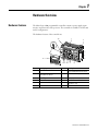
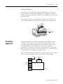
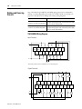
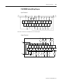
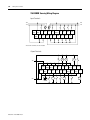
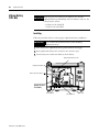
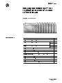
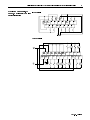
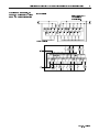
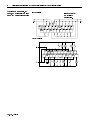
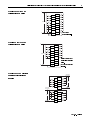
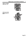
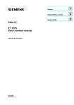
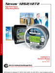
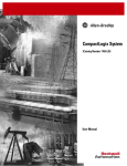
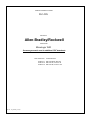
MANUFACTURER DATA SHEET PLC-CPU Manufacturer: Allen-Bradley/Rockwell Model Number: MicroLogic 1500 See www.geomartin.com for additional PDF datasheets Martin Part Number: VendorPartNumber: E-065167-01 AB# 1764-24BWA. Base Unit E-065174-00 AB# 1764-LSP, Processor 7K E-065167-00 AB# 1764-LRP, Processor 14K PDF File: Doc_000298_Cover.pdf This page is intentionally left blank MicroLogix™ 1500 Programmable Controllers (Bulletin 1764) User Manual Important User Information Because of the variety of uses for the products described in this publication, those responsible for the application and use of this control equipment must satisfy themselves that all necessary steps have been taken to assure that each application and use meets all performance and safety requirements, including any applicable laws, regulations, codes and standards. The illustrations, charts, sample programs and layout examples shown in this guide are intended solely for purposes of example. Since there are many variables and requirements associated with any particular installation, Rockwell International Corporation does not assume responsibility or liability (to include intellectual property liability) for actual use based upon the examples shown in this publication. Rockwell Automation publication SGI-1.1, Safety Guidelines for the Application, Installation and Maintenance of Solid-State Control (available from your local Rockwell Automation office), describes some important differences between solid-state equipment and electromechanical devices that should be taken into consideration when applying products such as those described in this publication. Reproduction of the contents of this copyrighted publication, in whole or part, without written permission of Rockwell Automation, is prohibited. Throughout this manual we use notes to make you aware of safety considerations: ATTENTION ! Identifies information about practices or circumstances that can lead to personal injury or death, property damage or economic loss Attention statements help you to: • identify a hazard • avoid a hazard • recognize the consequences IMPORTANT Identifies information that is critical for successful application and understanding of the product. 3/& LV D UHJLVWHUHG WUDGHPDUN DQG 0LFUR/RJL[ 6/& 56/RJL[ DQG 56/LQ[ DUH WUDGHPDUNV RI 5RFNZHOO $XWRPDWLRQ 0RGEXV LV D WUDGHPDUN RI 6FKQHLGHU $XWRPDWLRQ ,QFRUSRUDWHG 'HYLFH1HW LV D WUDGHPDUN RI 2SHQ 'HYLFH1HW 9HQGRU $VVRFLDWLRQ 2'9$ Chapter 1 Hardware Overview Hardware Features The MicroLogix 1500 programmable controller contains a power supply, input circuits, output circuits, and a processor. The controller is available in 24 I/O and 28 I/O configurations. The hardware features of the controller are: 1 10 2 RUN REM PROG 3 12 4 5 11 10 9 8 1 7 6 Feature Description Feature Description 1 Removable Terminal Blocks 7 Memory Module/Real-Time Clock(1) 2 Interface to Expansion I/O, Removable ESD Barrier 8 Replacement Battery(1) 3 Input LEDs 9 Battery 4 Output LEDs 10 Terminal Doors and Label 5 Communication Port 11 Data Access Tool(1) 6 Status LEDs 12 Mode Switch, Trim Pots (1) Optional. 1 Publication 1764-UM001A-US-P 1-2 Hardware Overview MicroLogix 1500 Component Descriptions A controller is composed of a standard processor (1764-LSP or enhanced 1764-LRP with RS-232 port) and one of the base units listed below. The FET transistor outputs are available on the 1764-28BXB base only. Base Units Catalog Number Base Unit I/O and Power Supply 1764-24AWA Twelve 120V ac inputs, twelve relay outputs and 120/240V ac power supply 1764-24BWA Twelve 24V dc inputs, twelve relay outputs and 120/240V ac power supply 1764-28BXB Sixteen 24V dc inputs, six FET and six relay outputs and 24V dc power supply Processors Processor (Catalog Number 1764-LSP) Processor (Catalog Number 1764-LRP) Communications Port • DTE (male) 9-pin D-shell connector • 30V dc isolation Publication 1764-UM001A-US-P Wiring Your Controller 3-3 Wiring with Spade Lugs The diameter of the terminal screw head is 5.5 mm (0.220 in.). The input and output terminals of the MicroLogix 1500 base unit are designed for a 6.35mm (0.25 in.) wide spade (standard for #6 screw for up to 14 AWG) or a 4 mm (metric #4) fork terminal. When using spade lugs, use a small, flat-blade screwdriver to pry the finger-safe cover from the terminal blocks as shown below. Then loosen the terminal screw. Finger-Safe Cover Using Surge Suppressors Inductive load devices, such as motor starters and solenoids, require the use of some type of surge suppression to protect and extend the operating life of the controller’s output contacts. Switching inductive loads without surge suppression can significantly reduce the life expectancy of relay contacts. By adding a suppression device directly across the coil of an inductive device, you prolong the life of the output or relay contacts. You also reduce the effects of voltage transients and electrical noise from radiating into adjacent systems. The following diagram shows an output with a suppression device. We recommend that you locate the suppression device as close as possible to the load device. +dc or L1 ac or dc Outputs VAC/ Out 0 Out 1 Out 2 Out 3 Out 4 Out 5 Out 6 Out 7 COM Suppression Device dc COM or L2 Publication 1764-UM001A-US-P 3-4 Wiring Your Controller If the outputs are dc, we recommend that you use an 1N4004 diode for surge suppression, as shown below. +24V dc Relay or Solid State dc Outputs VAC/ Out 0 Out 1 Out 2 Out 3 Out 4 Out 5 Out 6 Out 7 COM IN4004 Diode 24V dc common Suitable surge suppression methods for inductive ac load devices include a varistor, an RC network, or an Allen-Bradley surge suppressor, all shown below. These components must be appropriately rated to suppress the switching transient characteristic of the particular inductive device. See the table on page 3-5 for recommended suppressors. Surge Suppression for Inductive ac Load Devices Output Device Varistor Output Device RC Network Output Device Surge Suppressor If you connect an expansion I/O triac output to control an inductive load, we recommend that you use varistors to suppress noise. Choose a varistor that is appropriate for the application. The suppressors we recommend for triac outputs when switching 120V ac inductive loads are a Harris MOV, part number V175 LA10A, or an Allen-Bradley MOV, catalog number 599-K04 or 599-KA04. Consult the varistor manufacturer’s data sheet when selecting a varistor for your application For inductive dc load devices, a diode is suitable. A 1N4004 diode is acceptable for most applications. A surge suppressor can also be used. See the table on page 3-5 for recommended suppressors. Publication 1764-UM001A-US-P 3-8 Wiring Your Controller Terminal Block Layouts The base unit terminal block layouts are shown below. The shading on the labels indicates how the terminals are grouped. A detail of the groupings is shown in the table following the terminal block layouts. Group 0 DC COM 0 +24V Inputs DC POWER OUT 1764-24BWA Outputs VAC VDC 0 L2 85-265 VAC L1 Group 1 I/1 I/3 I/4 I/2 DC COM 1 I/5 I/7 I/8 I / 10 VAC VDC 1 VAC VDC 2 VAC VDC 3 VAC VDC 4 O/5 O/7 O/8 O / 10 O/1 O/2 O/4 O/3 VAC VDC 0 I/8 I / 10 VAC VDC 1 VAC VDC 2 VAC VDC 3 VAC VDC 4 O/5 O/7 O/8 O / 10 O/1 O/2 5 up 4 up Group 2 DC COM 2 I/6 I/9 I / 11 I / 15 I / 13 I/7 I/8 I / 10 I / 12 I / 14 VAC VDC 2 VDC 1 O/3 O/5 O/7 VAC VDC 3 O/9 O / 10 O/2 O/4 O/6 VDC COM 2 O/8 VAC VDC 4 28BXB 28BXB O / 11 4 up G ro 3 up G ro O/1 2 up G ro O/0 24AWA O / 11 I/5 I/2 24AWA G ro G ro 3 up I/4 O/9 DC COM 1 1 up G ro Publication 1764-UM001A-US-P O/6 VAC VDC 5 Group 1 I/3 0 up G ro +24V O/4 G ro 2 up VAC VDC 0 O/3 G ro 1 up COM 24 VDC I / 11 I/7 G ro Outputs I/0 I/9 I/5 0 up 1764-28BXB Group 2 AC COM 2 I/6 AC COM 1 I/1 NOT USED I/4 I/2 G ro Inputs DC COM 0 I/3 24BWA O / 11 I/0 Group 0 NOT USED Group 1 I/1 O/9 NOT USED O/0 L1 O/6 24BWA 5 up G ro L2 85-265 VAC AC COM 0 VAC VDC 5 4 up G ro 3 up G ro 2 up G ro 1 up G ro 0 up G ro Group 0 Outputs I / 11 I/0 NOT USED 1764-24AWA I/9 COM O/0 Inputs Group 2 DC COM 2 I/6 Wiring Your Controller 3-9 Terminal Groupings Controller 1764-24BWA 1764-24AWA 1764-28BXB Controller 1764-24BWA 1764-24AWA 1764-28BXB Inputs Input Group Group 0 Group 1 Group 2 Group 0 Group 1 Group 2 Group 0 Group 1 Group 2 Common Terminal DC COM 0 DC COM 1 DC COM 2 AC COM 0 AC COM 1 AC COM 2 DC COM 0 DC COM 1 DC COM 2 Input Terminal I/0 through I/3 I/4 through I/7 I/8 through I/11 I/0 through I/3 I/4 through I/7 I/8 through I/11 I/0 through I/3 I/4 through I/7 I/8 through I/15 Outputs Output Group Group 0 Group 1 Group 2 Group 3 Group 4 Group 5 Group 0 Group 1 Group 2 Group 3 Group 4 Group 5 Group 0 Group 1 Group 2 Group 3 Group 4 Voltage Terminal VAC/VDC 0 VAC/VDC 1 VAC/VDC 2 VAC/VDC 3 VAC/VDC 4 VAC/VDC 5 VAC/VDC 0 VAC/VDC 1 VAC/VDC 2 VAC/VDC 3 VAC/VDC 4 VAC/VDC 5 VAC/VDC 0 VAC/VDC 1 VDC 2, VDC COM 2 VAC/VDC 3 VAC/VDC 4 Output Terminal O/0 O/1 O/2 O/3 O/4 through O/7 O/8 through O/11 O/0 O/1 O/2 O/3 O/4 through O/7 O/8 through O/11 O/0 O/1 O/2 through O/7 O/8 and O/9 O/10 and O/11 Publication 1764-UM001A-US-P 3-10 Wiring Your Controller Sinking and Sourcing Circuits Any of the MicroLogix 1500 DC embedded input groups can be configured as sinking or sourcing depending on how the DC COM is wired on the group. See pages 3-11 through 3-14 for sinking and sourcing wiring diagrams. Type Definition Sinking Input The input energizes when high-level voltage is applied to connection of a PNP sourcing device the input terminal (active high). Connect the power supply VDC (-) to the DC COM terminal. The input energizes when low-level voltage is applied to Sourcing Input connection of an NPN sinking device the input terminal (active low). Connect the power supply VDC (+) to the DC COM terminal. 1764-24AWA Wiring Diagram Input Terminals L2 NOT AC IN 1 USED COM 0 NOT USED IN 0 IN 3 IN 4 IN 6 AC IN 2 COM 1 IN 5 AC IN 9 COM 2 IN 7 IN 8 IN 11 IN 10 L1 L2 L1 “NOT USED” terminals are not intended for use as connection points. Output Terminals CR CR L2 (Lo) VAC VAC/ VAC/ VAC/ VAC/ VAC/ NEUT VDC 0 VDC 1 VDC 2 VDC 3 VDC 4 OUT 5 OUT 7 OUT 8 OUT 10 VAC/ 120/240 EARTH OUT 0 OUT 1 OUT 2 OUT 3 OUT 4 OUT 6 OUT 9 OUT 11 VDC 5 VAC GND (Hi) L1 Publication 1764-UM001A-US-P CR CR CR CR Wiring Your Controller 3-11 1764-24BWA Sinking Wiring Diagram Input Terminals +24V DC IN 1 POWER OUT COM 0 IN 0 COM IN 3 IN 2 IN 4 IN 6 DC IN 5 COM 1 -DC DC COM 2 IN 7 IN 8 IN 9 IN 11 IN 10 +DC Output Terminals CR CR L2 (Lo) VAC VAC/ VAC/ VAC/ VAC/ VAC/ OUT 5 OUT 7 OUT 8 OUT 10 NEUT VDC 0 VDC 1 VDC 2 VDC 3 VDC 4 120/240 EARTH VAC/ VAC GND OUT 0 OUT 1 OUT 2 OUT 3 OUT 4 OUT 6 VDC 5 OUT 9 OUT 11 (Hi) L1 CR CR CR CR Publication 1764-UM001A-US-P 3-12 Wiring Your Controller 1764-24BWA Sourcing Wiring Diagram Input Terminals +24V POWER DC IN 1 OUT COM 0 COM IN 0 IN 2 IN 3 IN 4 DC IN 5 COM 1 IN 6 DC IN 9 COM 2 IN 7 IN 8 IN 11 IN 10 +DC -DC Output Terminals CR L2 CR (Lo) VAC VAC/ VAC/ VAC/ VAC/ VAC/ NEUT VDC 0 VDC 1 VDC 2 VDC 3 VDC 4 OUT 5 OUT 7 OUT 8 OUT 10 VAC/ 120/240 EARTH OUT 0 OUT 1 OUT 2 OUT 3 OUT 4 OUT 6 OUT 9 OUT 11 VDC 5 VAC GND L1 Publication 1764-UM001A-US-P (Hi) CR CR CR CR Wiring Your Controller 3-13 1764-28BXB Sinking Wiring Diagram Input Terminals -DC +DC -DC +DC NOT DC IN 1 USED COM 0 NOT IN 0 USED IN 3 IN 2 IN 4 IN 6 DC IN 5 COM 1 DC IN 9 COM 2 IN 7 IN 8 IN 11 IN 13 IN 15 IN 10 IN 12 IN 14 “NOT USED” terminals are not intended for use as connection points. Output Terminals CR CR CR -DC COM VAC/ VAC/ VDC 2 OUT 3 OUT 5 OUT 7 VAC/ OUT 9 OUT 10 VDC 0 VDC 1 VDC 3 +24v EARTH OUT 0 OUT 1 OUT 2 OUT 4 OUT 6 VDC OUT 8 VAC/ OUT 11 COM 2 GND VDC 4 +DC CR CR CR Publication 1764-UM001A-US-P 3-14 Wiring Your Controller 1764-28BXB Sourcing Wiring Diagram Input Terminals +DC -DC +DC -DC NOT DC IN 1 USED COM 0 NOT IN 0 USED IN 3 IN 2 IN 4 IN 6 DC IN 5 COM 1 DC IN 9 COM 2 IN 7 IN 8 IN 11 IN 13 IN 15 IN 10 IN 12 IN 14 “NOT USED” terminals are not intended Output Terminals CR CR CR -DC COM +24V +DC Publication 1764-UM001A-US-P VAC/ VAC/ VAC/ OUT 9 OUT 10 VDC 2 OUT 3 OUT 5 OUT 7 VDC 3 VDC 0 VDC 1 VDC VAC/ EARTH OUT 0 OUT 1 OUT 2 OUT 4 OUT 6 OUT 8 OUT 11 COM 2 VDC 4 GND CR CR CR B-2 Replacement Parts Lithium Battery (1747-BA) IMPORTANT When the processor’s Battery Low indicator is lit, install a replacement battery immediately. After the indicator turns on, the battery lasts for at least: • 14 days for the 1764-LSP • 7 days for the 1764-LRP Installing Follow the procedure below to ensure proper replacement battery installation. IMPORTANT Do not remove the permanent battery when installing replacement battery. 1. Insert battery into replacement battery pocket with wires facing up. 2. Insert replacement battery wire connector into connector port. 3. Secure battery wires under wire latch (as shown below). Replacement Battery Pocket Replacement Battery DC INPUTS Battery Connector Wires 24V SINK/SOURCE DC/RELAY OUT 24V SOURCE Permanent Battery (DO NOT ATTEMPT TO REMOVE) Connector Port Publication 1764-UM001A-US-P Wire Connector Wire Latch 9DEJA 2=FAH Wiring Diagrams for MicroLogix 1500 Programmable Controllers and Compact Discrete I/O Modules (Bulletin 1764 and 1769) List of Diagrams Description Page 1764-24AWA Base Unit, AC Power, 12 AC Inputs/ 12 Relay Outputs 2 1764-24BWA Base Unit, AC Power, 12 DC Inputs/ 12 Relay Outputs 1764-28BXB Base Unit, DC Power, 16 DC Inputs/ 6 Relay and 6 FET Outputs Sinking 3 Sourcing 4 Sinking 5 Sourcing 6 1769-IA16 100/120V ac 16-Point Input Module 7 1769-IM12 200/240V ac 12-Point Input Module 7 1769-IQ16 24V dc Sinking/Sourcing 16-Point Input Module 7 1769-IQ6XOW4 24V dc Sinking/Sourcing 6-Point Input, AC/DC 4-Point Normally Open Relay Output Module 8 1769-OA8 100 to 240V ac 8-Point Output Module 8 1769-OB16 24V dc Sourcing 16-Point Output Module 8 1769-OV16 24V dc Sinking 16-Point Output Module 9 1769-OW8 AC/DC Normally Open Relay 8-Point Output Module 9 1764-901 - April 1999 2 Wiring Diagrams for MicroLogix 1500 Programmable Controllers and Compact Discrete I/O Modules 1764-24AWA Base Unit, AC Power, 12 AC Inputs/ 12 Relay Outputs Input Terminals Output Terminals 1764-901 - April 1999 Note: Do not use the NOT USED terminals as connection points. Wiring Diagrams for MicroLogix 1500 Programmable Controllers and Compact Discrete I/O Modules 1764-24BWA Base Unit, AC Power, 12 DC Inputs/ 12 Relay Outputs - Sinking ! Input Terminals Output Terminals 1764-901 - April 1999 " Wiring Diagrams for MicroLogix 1500 Programmable Controllers and Compact Discrete I/O Modules 1764-24BWA Base Unit, AC Power, 12 DC Inputs/ 12 Relay Outputs - Sourcing Input Terminals Output Terminals 1764-901 - April 1999 Wiring Diagrams for MicroLogix 1500 Programmable Controllers and Compact Discrete I/O Modules 1764-28BXB Base Unit, DC Power, 16 DC Inputs/ 6 Relay and 6 FET Outputs - Sinking 5 Input Terminals Note: Do not use the NOT USED terminals as connection points. Output Terminals 1764-901 - April 1999 6 Wiring Diagrams for MicroLogix 1500 Programmable Controllers and Compact Discrete I/O Modules 1764-28BXB Base Unit, DC Power, 16 DC Inputs/ 6 Relay and 6 FET Outputs - Sourcing Input Terminals Note: Do not use the NOT USED terminals as connection points. Output Terminals 1764-901 - April 1999 Wiring Diagrams for MicroLogix 1500 Programmable Controllers and Compact Discrete I/O Modules 1769-IA16 100/120V ac 16-Point Input Module 7 L1 IN 0 IN 1 IN 2 IN 3 IN 4 IN 5 IN 6 100/120V ac IN 7 IN 8 IN 9 IN 10 IN 11 IN 12 IN 13 IN 14 IN 15 AC COM L2 1769-IM12 200/240V ac 12-Point Input Module AC COM Commons are connected internally. L1 IN 0 IN 1 IN 2 IN 3 IN 4 IN 5 IN 6 200/240V ac IN 7 IN 8 IN 9 IN 10 IN 11 Note: Do not use the NC terminals as connection points. NC NC NC NC AC COM L2 1769-IQ16 24V dc Sinking/ Sourcing 16-Point Input Module AC COM Commons are connected internally. +DC (sinking) -DC (sourcing) IN 0 IN 1 IN 2 24V dc IN 3 IN 4 IN 5 IN 6 IN 7 +DC (sinking) -DC (sourcing) DC COM 1 -DC (sinking) +DC (sourcing) IN 9 IN 8 IN 11 24V dc IN 10 IN 13 IN 12 IN 15 -DC (sinking) +DC (sourcing) DC COM 2 IN 14 1764-901 - April 1999 8 Wiring Diagrams for MicroLogix 1500 Programmable Controllers and Compact Discrete I/O Modules 1769-IQ6XOW4 24V dc Sinking/ Sourcing 6-Point Input, AC/DC 4-Point Normally Open Relay Output Module CR OUT 0 CR OUT 2 VAC VDC L1 or +DC OUT 1 CR OUT 3 CR NC NC NC NC NC L2 or -DC Note: Do not use the NC terminals as connection points. NC +DC (sinking) -DC (sourcing) IN 0 IN 1 24V dc IN 2 IN 3 IN 4 IN 5 DC COM -DC (sinking) +DC (sourcing) 1769-OA8 100 to 240V ac 8-Point Output Module L1 VAC 1 CR OUT 0 CR OUT 2 OUT 1 CR OUT 3 CR 100 to 240V ac L2 L1 VAC 2 100 to 240V ac CR OUT 4 CR OUT 6 OUT 5 CR OUT 7 CR L2 1769-OB16 24V dc Sourcing 16-Point Output Module +DC +VDC CR OUT 0 CR OUT 2 OUT 1 CR OUT 3 CR OUT 4 OUT 5 CR OUT 6 CR OUT 8 OUT 7 CR OUT 9 CR OUT 11 CR OUT 13 CR 24V dc (source) OUT 10 OUT 12 OUT 14 OUT 15 DC COM -DC 1764-901 - April 1999 Wiring Diagrams for MicroLogix 1500 Programmable Controllers and Compact Discrete I/O Modules 1769-OV16 24V dc Sinking 16-Point Output Module +DC +VDC CR OUT 0 CR OUT 2 ' OUT 1 CR OUT 3 CR OUT 4 OUT 5 CR OUT 6 CR OUT 8 OUT 7 CR OUT 9 CR OUT 11 CR OUT 13 CR 24V dc (sink) OUT 10 OUT 12 OUT 14 OUT 15 DC COM -DC 1769-OW8 AC/DC Normally Open Relay 8-Point Output Module OUT 0 CR L2 or -DC L1 or +DC OUT 1 CR OUT 3 CR OUT 5 CR L2 or -DC OUT 2 VAC-VDC 2 L1 or +DC VAC-VDC 1 CR OUT 4 CR OUT 6 OUT 7 1764-901 - April 1999 Publication 1764-901 - April 1999 Supersedes Publication xxxxxxx-xx - xxxxxxx-xx PN xxxxxxx-xx © 1999 Rockwell International Corporation. All rights reserved. Printed in the U.S.A.