1
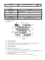
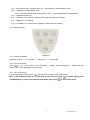
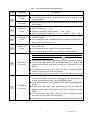
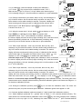
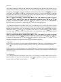
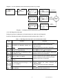
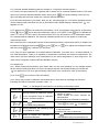
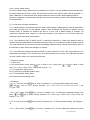
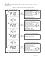
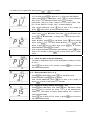
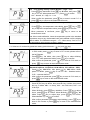
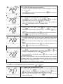
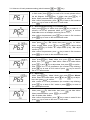
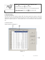
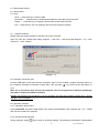
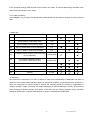
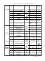
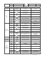
70 Series
pH/Conductivity Portable Meter
Manual
PH 70 Portable pH Meter
COND 70 Portable Cond. Meter
PC 70 Portable pH/Cond. Meter
PC70 Version1.4
Table of Contents
1. Introduction --------------------------------------------------------------------------------------------------------------------------1
2. Specifications ------------------------------------------------------------------------------------------------------------------------2
3. Instrument Description ------------------------------------------------------------------------------------------------------------3
3.1. LCD display---------------------------------------------------------------------------------------------------------------------3
3.2. Keypad functions --------------------------------------------------------------------------------------------------------------4
3.3. Meter socket ---------------------------------------------------------------------------------------------------------------------6
3.4. Reading stability display mode-----------------------------------------------------------------------------------------------6
3.5. Store, recall and clear readings--------------------------------------------------------------------------------------------6
3.6. Auto. power off ---------------------------------------------------------------------------------------------------------------7
4. pH measurement -------------------------------------------------------------------------------------------------------------------7
4.1. pH electrode information-----------------------------------------------------------------------------------------------------7
4.2. pH calibration consideration ------------------------------------------------------------------------------------------------7
4.3. pH calibration -------------------------------------------------------------------------------------------------------------------9
4.4. Customer-defined calibration ------------------------------------------------------------------------------------------------9
4.5. Sample test ----------------------------------------------------------------------------------------------------------------------10
4.6. pH electrode maintenance---------------------------------------------------------------------------------------------------12
5. mV measurement--------------------------------------------------------------------------------------------------------------------13
6. Conductivity measurement ---------------------------------------------------------------------------------------------------------13
6.1. Conductivity electrode information------------------------------------------------------------------------------------------13
6.2. Conductivity calibration consideration------------------------------------------------------------------------------------14
6.3. Conductivity calibration-------------------------------------------------------------------------------------------------------16
6.4. Relations between TDS and conductivity--------------------------------------------------------------------------------16
6.5. Customer-defined calibration-------------------------------------------------------------------------------------------------17
6.6. Sample test-----------------------------------------------------------------------------------------------------------------------17
6.7 Conductivity electrode maintenance----------------------------------------------------------------------------------------18
7. Parameter setting---------------------------------------------------------------------------------------------------------------------18
7.1. Main menu------------------------------------------------------------------------------------------------------------------------18
7.2. Submenu -------------------------------------------------------------------------------------------------------------------------18
7.3. Submenu of pH parameter setting ------------------------------------------------------------------------------------------20
7.4. Conductivity parameter setting submenu--------------------------------------------------------------------------------21
7.5. Submenu of TDS parameter setting --------------------------------------------------------------------------------------22
7.6. Submenu of basic parameter setting ---------------------------------------------------------------------------------------23
8. USB communication------------------------------------------------------------------------------------------------------------------24
9. Meter Kits--------------------------------------------------------------------------------------------------------------------------------26
10. Warranty-------------------------------------------------------------------------------------------------------------------------------26
Appendix I: Parameter setting and factory restoring setting------------------------------------------------------------------27
Appendix II: Abbreviation Glossary--------------------------------------------------------------------------------------------------28
Appendix III: Self-diagnosis information--------------------------------------------------------------------------------------------29
PC70 Version1.4
1. Introduction
Thanks for purchasing 70 series portable pH/Conductivity meter.
This meter is perfect combination of the most advanced electronics, sensor technology and software
design, and is the most cost effective portable electrochemical meter suited for industrial and mining
enterprises, power plant, water treatment engineering, environmental protection industry, etc,
especially suited for application in field.
In order to use and maintain the instrument properly, please read the manual thoroughly before use.
To improve instrument performance constantly, we reserve the right to change the manual and
accessories without giving notice in advance.
1.1. Measurement parameters
Measurement
parameters
pH70
pH/mV
√
COND70
√
Conductivity/TDS
Temperature
PC70
√
√
√
√
√
1.2. Basic features
● The microprocessor-based portable meter features automatic calibration, automatic temperature
compensation, function set-up, self-diagnostics, due calibration reminding, calibration date
checking, automatic power-off and low voltage display.
● Meet GLP, clock display, manual storage and automatic timing storage, USB port.
● The meter’s digital filter improves measurement speed and accuracy. There is reading stability
display.
● The package includes portable case, meter, electrode, standard solutions and all accessories,
convenient to use in field.
● The meter is dust-proof and water-proof, meeting the IP57 rating.
● Temperature calibration function.
1.3. pH measurement features (suited for model PH70 and PC70)
● 1-3 point automatic calibration, the meter provides calibration guide and automatic checking
function.
● The meter is able to recognize up to 8 types of pH standard buffer solutions. There are three
options of standard buffer solution: USA series, NIST series and customer-defined solution
set-up.
● The meter provides reading stability criteria.
1.4. Conductivity measurement features (suited for model COND70 and PC70)
● 1-4 point automatic calibration, the meter provides calibration guide and automatic checking
function.
● The meter is able to switch among conductivity, TDS and salinity measurement mode.
1
PC70 Version1.4
● The meter is able to switch between conductivity and TDS measurement mode.
● The meter is able to recognize up to 4 types of conductivity standard solutions. There is
customer-defined solution set-up.
2.
Specifications
2.1. Main specifications
Specifications
Range
(-2.00 ~ 16.00)pH
Resolution
0.1/0.01 pH
Accuracy
±0.01 pH ±1digit
Temperature
compensation
Multi-point
calibration
pH
mV
Models
(0 ~ 100)°C(manual or automatic)
1-3 point
PH 70
PC 70
Buffer value
USA: 1,68-4,00-7,00-10,01pH
NIST: 1,68-4,01-6,86-9,18pH
2 value CUSTOMER
Range
±1,999mV
Resolution
±200 mV :0.1 mV ;others:1mV
Accuracy
±0.1% FS ±1digit
Conductivity:0~200 mS/cm,divided into five ranges:
(0.00~19.99)μS/cm (20.0~199.9)μS/cm
Range
(200~1999)μS/cm (2.00~19.99)mS/cm
(20.0~199.9)mS/cm
TDS:(0 ~ 100)g/L, Salinity: (0 – 100) ppt
Resolution
Conductivity
Temperature
0.01/0.1/1μS/cm
0.01/0.1 mS/cm
C0ND 70
Accuracy
±1.0% FS ±1digit
Temperature
compensation
(0 ~ 100)°C(manual or automatic)
Multi-point
calibration
1-4 point
Standard solution
84 μS/cm, 1413 μS/cm, 12.88, 111,9 mS/cm
1 customer value
Electrode constant
0.1 / 1 / 10 cm-1
Range
-10~110°C
Resolution
0.1℃
Accuracy
±0.5℃±1digit
PC 70
PH 70
C0ND 70
PC 70
Reading stability criteria
Low:1.2mV/10 sec., Medium:0.6mV/10 sec.,
High:0.3mV/10 seconds
PH 70
PC 70
Due calibration
Remind due calibration
PH 70
PC 70
2
PC70 Version1.4
Out of test
PH 70
PC 70
Electrode provides error
2.2. Other specifications:
Data storage
500 groups
Storage content
Serial number, date, time, measuring value, measuring unit and
temperature value
Output
USB
Power
AAA batteries × 3 (1.5V× 3) / 220 V with USB power supply
IP rating
IP57
Dimension & Weight
Meter: (86×196×33 )mm / 335g
3. Instrument description
3.1. LCD display:
Diagram-1
(1) — Parameter mode icons
(2) — Measurement reading
(3) — Timing storage icon. When this icon appears, the meter is in the automatic storage mode
(4) — Time(appears with (5), and prompts of special display mode
(5) — Date(appears with (4))
(6) — Units of measurement
(7) — Temperature units (°C and °F)
(8) — Units of pH and conductivity calibration value(appears with(9))
(9) — pH and conductivity calibration value(appears with (8)), the serial number for storage and recall
(appears with (10)), and prompts of special display mode
(10) — Storage and recall icons
M+ — Measurement to be stored icon, RM — Reading to be recalled icon
3
PC70 Version1.4
(11) — Temperature value(appears with (7)), and prompts of special display mode
(12) — Temperature compensation icons
ATC — automatic temperature compensation, MTC — manual temperature compensation
(13) — Calibration guide icon
(14) — USB icon,when this icon appears, the meter connects the computer
(15) — Stability icon of readings
(16) —Low battery icon, when this icon appears, please renew the battery
3.2. Keypad functions
Diagram-2
3.2.1. Keypad operations
Momentary press ----- <1.5 seconds , Long press ----- >1.5 seconds.
3.2.2. Turn on the meter
Press
to turn on the meter: LCD full display → display some parameters → display the last
measurement mode (backlight for one minute).
3.2.3. Turn off the meter
In the measurement mode, press
and hold for 2 seconds to turn off the meter.
Note: In the calibration mode or the parameter set-up mode, pressing
is invalid. Please press
CAL/MEAS key to return to the measurement mode, then press
to turn off the meter.
4
PC70 Version1.4
Chart – 1 Keypad operations and descriptions
Keypad
Operations
Descriptions
Momentary
press
● In the power-off mode, press this key to turn on the meter
● In the measurement mode, press this key to turn on or turn off the
backlight display.
Long press
● In the measurement mode, press and hold this key for 2 seconds to turn
off the meter.
Momentary
press
Measurement mode:
● PH70 pH meter: pH → mV,
● COND70 Conductivity meter: COND → TDS → SAL ,
● PC70 pH/Conductivity meter: pH → mV → COND → TDS → SAL
Momentary
press
● In the measurement mode, press this key to enter in the
calibration mode
● In the calibration mode or the parameter set-up mode, press this key to
return to the measurement mode
Momentary
press
● In the measurement mode, press this key to enter in the parameter
set-up main menu
● In the calibration mode, press this key to make calibration
● In the parameter set-up mode, press this key to select programs
Momentary/
long press
● In the mode of manual temperature compensation (MTC), when press
and hold this key, the temperature value flashes, then press this key to
change the temperature value, and press
to confirm
● In the measurement mode, press this key to store the measuring value.
● In the recall mode (RM), press momentarily this key to change the
storage serial number, press and hold this key to change the number
quickly
● In the parameter set-up mode, press this key to change the serial
number of the main menu and the submenu
● In the submenu mode, press this key to change parameters and set-up
Momentary/
long press
● In the mode of manual temperature compensation (MTC), when press
and hold this key, the temperature value flashes, then press this key to
change the temperature value, and press
to confirm
● In the measurement mode, press this key to recall the stored measuring
value.
● In the recall mode (RM), press momentarily this key to change the
storage serial number, press and hold this key to change the number
quickly
● In the parameter set-up mode, press this key to change the serial
number of the main menu and the submenu
● In the submenu mode, press this key to change parameters and set-up
5
PC70 Version1.4
3.3. Meter socket
Electrode socket uses BNC and RCA. USB socket uses standard type. The following chart is socket for
model PH70, COND70 and PC70:
Chart – 2 Sockets for meters
Models
Photos
Description
PH70 pH meter
•BNC socket (right) — connect pH
electrode or ORP electrode,
• RCA socket (middle) — connect
temperature probe
COND70 Conductivity meter
•BNC socket (left) —
connect conductivity electrode,
• RCA socket (middle) — connect
temperature probe
PC70 pH/Conductivity meter
•BNC socket (right) — connect pH
electrode or ORP electrode,
•BNC socket(left) —
connect conductivity electrode,
• RCA socket (middle) — connect
temperature probe
3.4. Reading stability display mode
When the measuring value is stable, smiley icon
appears on LCD,
see Diagram – 3. If the
icon does not appear or flash, please do not
get the reading value or make calibration until the measuring value is stable.
Per parameter P1.6, there are 3 criteria for stability standard:
(Normal),
(High) and
(Low). The factory default
is set “Normal”. “High” is set for stability for longer time, “Low” is set for
stability for shorter time. User can select suitable stability criteria
according to different testing requirement.
3.5. Store, recall and clear readings
3.5.1. Manual storage
When the measurement is stable, press momentarily
Diagram - 3
key,
M+ icon and storage serial number appear on LCD, storing measuring
information, see Diagram – 4.
3.5.2. Automatic timing storage
Set the storage timing (eg. 3 minutes) per parameter P6.3,
icon appears on LCD and the meter enters into the timing storage
mode. When press momentarily
key,
key flashes and
the first measuring value is stored. After 3 minutes, the 2nd measuring
value is stored. See Diagram – 5: the meter stores automatically eight
measuring values. When press momentarily
key,
icon
stops flashing and the meter stops automatic storage. In automatic storage
mode, manual storage does not work. Set time 0 per parameter
P6.3 to exit from the automatic storage mode.
6
Diagram - 4
Diagram - 5
PC70 Version1.4
3.5.3. Recall stored value
In the measurement mode, press
key to recall the last stored
measuring value. See Diagram – 6: display RM icon and storage
serial number. Continue pressing
key and
key to recall
successively the stored measuring value.
Press and hold
key and
key to recall quickly
the stored measuring value.
Diagram - 6
3.5.4. Clear stored value
Select YES per parameter P6.7 to clear all stored value, refer to clause 7.6.
3.6. Automatic power-off
The meter will be power-off after the meter stops operation for 20 minutes. During Auto Logging
Automatic power-off disable.
4. pH measurement
4.1. pH electrode information
The meter matches 201T-F plastic three-in-on combination pH electrode with built-in temperature sensor
to realize automatic temperature compensation. Electrode housing adopts polycarbonate engineering
plastics which is corrosion and impact resistant. The BNC socket of electrode connects pH socket, RCA
socket connects temperature socket. When dip the electrode in the solution, please stir the solution briefly
and allow it to stay in the solution until a stable reading is reached.
4.2. pH calibration consideration
4.2.1. Standard buffer solution
The meter uses two series of standard buffer solution: USA series and NIST series, and also
customer-defined solution. Please see Chart - 3 for the two series of standard buffer solution. For
customer-defined solution, please select it per parameter P1.1 and refer to clause 7.3 for details.
Chart - 3 pH standard buffer solution series
Icons
pH standard buffer solution series
USA Series
NIST series
1.68 pH and 4.00 pH
1.68 pH and 4.01 pH
7.00 pH
6.86pH
10.01 pH
9.18 pH
Three-point calibration
4.2.2. Three-point calibration
The instrument can perform 1-3 point calibration. The first point calibration must use 7.00 pH (or 6.86 pH)
standard solution, then select other standard solution to perform the second and the third point calibration,
see Chart-4. During the calibration process, the instrument displays the electrode slope of acidity range
and alkalinity range respectively.
7
PC70 Version1.4
Chart - 4 Three-point calibration mode
USA standard
NIST standard
7.00 pH
6.86 pH
Accuracy
≤ ±0.1pH
7.00 pH,
4.00 pH or 1.68 pH
6.86 pH,
4.01 pH or 1.68 pH
Range<7.00pH
7.00 pH and 10.01pH 6.86 pH and 9.18pH
Range>7.00pH
One-point calibration
Two-point calibration
Three-point calibration
7.00 pH, 4.00 pH or
1.68 pH, 10.01 pH
Icons
Suited range
6.86 pH, 4.01 pH or
1.68 pH, 9.18 pH
Large Range
4.2.3. Calibration intervals
Calibration intervals depend on the sample, the electrode performance, and the required accuracy. For
high accuracy measurements (≤ ±0.02pH), the meter should be calibrated immediately before taking a
measurement. For general accuracy (≥±0.1pH), the meter can be calibrated and used for approximately
one week before the next calibration.
The meter must be recalibrated in the following situations:
(a) New probe, or probe that is unused for a long period of time
(b) After measuring acids (pH<2) or alkaline solutions (pH>12)
(c) After measuring a solution that contains fluoride or a concentrated organic solution
(d) If the solution’s temperature differs greatly from the calibration solution temperature
4.2.4. Due calibration
Pre-set calibration interval (begin from the date of last calibration) to
remind due calibration in a preset period per parameter P1.2 (clause 7.3).
During due calibration, Er 7 icon appears on LCD (see Diagram – 7).
The meter can not continue operation and Er 7 icon disappears until
the calibration is done, or when select No per parameter P1.2.
Diagram - 7
4.2.5. Check calibration date
Check the date and time of last calibration to decide whether new
calibration is needed. Please refer to parameter setting P1.3 (clause 7.3).
8
PC70 Version1.4
4.3. pH calibration ( take an example of three-point calibration)
4.3.1. Press
key to enter into the calibration mode, “CAL 1”
blinks at the top right of LCD and “7.00 pH ”blinks at the bottom right of
LCD, indicating using pH 7.00 buffer solution to make the 1st point calibration.
4.3.2. Rinse pH electrode in pure water, allow it to dry, and submerge it in
pH7.00 buffer solution. Stir the solution briefly and allow it to stay in the
buffer solution until a stable reading is reached. The meter’s display will
show scanning and locking process of calibration buffer solution at the
bottom right of LCD. Er 2 displays if press
is locked. See Chart – 5.
4.3.3. When the meter locks 7.00 pH, stable
key before the value
icon displays on LCD.
Press
key to calibrate the meter. End icon appears after
calibration is done. The 1st point calibration is finished, meanwhile,
the meter’s display will show at the top right a blinking CAL2, and show at the
bottom right blinking 4.00pH and 10.01pH alternately, indicating using
pH4.00 or pH10.01 buffer solution to make the 2nd point calibration.
4.3.4. Take out pH electrode,rinse it in pure water, allow it to dry, and
submerge it in pH4.00 buffer solution. Stir the solution briefly and allow it to
stay in the buffer solution until a stable reading is reached. The meter’s
display will show scanning and locking process of calibration buffer solution
at the bottom right of LCD. When the meter locks 4.00 pH, stable
icon
displays on LCD. Press
key to calibrate the meter. End icon and
electrode slope of acidity range display after calibration is done, meanwhile,
the meter’s display will show at the top right a blinking CAL3, and show at the
bottom right blinking 10.01pH, indicating using pH10.01 buffer solution to make
the 3rd point calibration.
4.3.5. Take out pH electrode,rinse it in pure water, allow it to dry, and
submerge it in pH10.01 buffer solution. Stir the solution briefly and allow it to
stay in the buffer solution until a stable reading is reached. The meter’s
Diagram - 8
display will show scanning and locking process of calibration buffer solution at the bottom right of LCD.
When the meter locks 10.01 pH, stable
icon displays on LCD. Press
key to calibrate the meter.
End icon and electrode slope of alkalinity range display after calibration is done. The meter goes to the
measurement mode, displays stable measuring value and calibration guide icons.Please see Diagram – 8
for the above calibration process.
4.3.6. During the calibration process, press
key to exit from the calibration mode. The meter can
perform one-point, two-point and three-point calibration. Calibration guide icons appear on LCD.
4.4. Customer-defined calibration (take an example of 1.60pH and 6.50pH calibration solution)
4.4.1. Select CUS per parameter P1.1 (please refer to clause 7.3 for customer-defined solution). The
meter enters into Customer-defined calibration mode. Press
key, the meter’s display show a blinking
CAL1 icon at the top right of LCD, indicating the meter enters into the 1st point customer-defined
9
PC70 Version1.4
calibration.
4.4.2. Rinse pH electrode in pure water, allow it to dry, and submerge it in pH1.60 buffer solution. Stir the
solution briefly and allow it to stay in the buffer solution until a stable reading is reached. For automatic
temperature compensation (ATC), the temperature value does not blink. When press
key, the main
value blinks. Press
key or
key to adjust the main value to 1.60, then press
key to calibrate
the meter. After calibration is done, LCD at the top right shows blinking CAL2 icon, indicating the meter
enters into the 2nd point customer-defined calibration.
Note: For manual temperature compensation (MTC), when LCD displays the stable measuring
value and
icon, press
key, then the temperature value blinks, Press
key or
key
to adjust the temperature value, and press
key to confirm it. Then the main value blinks.
Follow the above procedures to adjust the main value and calibrate the meter.
4.4.3. Rinse pH electrode in pure water, allow it to dry, and submerge it in pH 6.50 buffer solution. Stir the
solution briefly and allow it to stay in the buffer solution until a stable reading is reached. For automatic
temperature compensation (ATC), the temperature value does not blink. When press
key, the main
value blinks. Press
key or
key to adjust the main value to 6.50, then press
key to calibrate
the meter. After calibration is done, the meter goes to the measurement mode. For customer-defined
calibration, LCD does not show electrode calibration guide icons.
Note: For manual temperature compensation (MTC), when LCD displays the stable measuring
value and smiley icon, press
key and the temperature value blinks. Press
key or
key
to adjust the temperature value, and press
to confirm it. Then the main value blinks. Follow
the above procedures to adjust the main value and calibrate the meter.
4.4.4. Notes
(a) The meter can perform 1-2 point customer-defined calibration. When the 1st point calibration is done,
press
key, the meter exits from calibration mode. This is one-point customer-defined calibration.
(b) The value set in “Customer-defined” is at a fixed temperature. The meter has to perform calibration and
measurement at the same temperature to avoid large error. The meter cannot recognize customer-defined
calibration solution.
4.5. Sample test
4.5.1. Rinse pH electrode in pure water, allow it to dry, and submerge it in tested solution. Stir the solution
briefly and allow it to stay in the tested solution until
icon appears on LCD and a stable reading is
reached which is pH value of tested solution.
10
PC70 Version1.4
Diagram – 9 is the calibration and measurement process of pH meter
Press
to turn on
the meter.
Press
key to enter
into the calibration
mode.
Submerge the electrode
in pH7.00 solution, press
key when
icon
appears.
Submerge the electrode
in pH4.00 solution, press
key when
icon
appears.
Submerge the electrode
in pH10.01solution,press
key when
icon
appears.
After the 1st point st
calibration is done, 1 point calibration
press
key to enter
into the measurement
mode.
After the 2nd point
calibration is done,
press
key to enter
into the measurement
mode.
After the 3rd point
calibration is done, the
meter enters into the
measurement
mode
automatically.
2nd point
calibration
Sample
Test
3r dpoint
calibration
Diagram – 9 Calibration and measurement process of pH meter
4.5.2. Self-diagnosis information
During the process of calibration and measurement, the meter has self-diagnosis
functions, indicating the relative information as below, please refer to Chart – 5.
Chart – 5 Self-diagnosis information of pH measurement mode
Display
Icons
Contents
Checking
Wrong pH buffer solution or the meter
recognition of calibration solution out of
range
1.Check whether pH buffer solution is correct.
2.Check whether the meter connects the
electrode well.
3.Check whether the electrode is damaged.
Press
key when measuring value is
not stable during calibration.
Press
During calibration, the measuring value is
not stable for ≥3min.
1.Check whether there are bubbles in glass bulb.
2.Replace with new pH electrode.
Electrode zero electric potential out of
range (<-60mV or >60mV)
Electrode slope out of range(<85% or
>110%)
key when
icon appears
1.Check whether there are bubbles in glass bulb.
2.Check whether pH buffer solution is correct.
3.Replace with new pH electrode.
pH measuring range out of range(<-2.00
pH or >16.00pH)
1.Check whether the electrode is suspended.
2.Check whether the meter connects the
electrode well.
3.Check whether the electrode is damaged
Enter in pre-set due calibration to remind
due calibration
Press
key to perform calibration or cancel due
calibration setup per parameter P1.2
11
PC70 Version1.4
4.5.3. pH temperature principle
Note that the closer the temperature of the sample solution to the calibration solution, the more
accurate readings
4.5.4. Factory default setting
For factory default setting, please refer to parameter P1.5 (clause 7.3). Per parameter P1.5, all calibration
data is deleted and the meter restores to the theory value (zero electric potential of pH is 7.00, the slope is
100%). Some functions restore to the original value (refer to appendix -1). When calibration or
measurement fails, please restore the meter to factory default setting and then perform re-calibration or
measurement. Please note once set the factory default, all the data deleted will not be retrievable.
4.6. pH electrode maintenance
4.6.1. Daily maintenance
The soaking solution contained in the supplied protective bottle is used to maintain activation in the glass
bulb and junction. Loosen the capsule, remove the electrode and rinse in pure water before taking a
measurement. Insert the electrode and tighten the capsule after measurements to prevent the solution
from leaking. If the soak solution is turbid or moldy, replace the solution.
The electrode should not be soaked in pure water, protein solution or acid fluoride solution for long periods
of time. In addition, do not soak the electrode in organic silicon lipids.
For best accuracy, always keep the meter clean and dry, especially the meter’s electrode and electrode
jack. Clean with medical cotton and alcohol if necessary.
4.6.2. Calibration buffer solution
For calibration accuracy, the pH of the standard buffer solution must be reliable. The buffer solution should
be refreshed often, especially after heavy use.
4.6.3. Protect glass bulb
The sensitive glass bulb at the front of the combination electrode should not come in contact with hard
surfaces. Scratches or cracks on the electrode will cause inaccurate readings. Before and after each
measurement, the electrode should be washed with pure water and dried. Do not clean the glass bulb with
a tissue for it will affect the stability of the electrode potential and increase the response time. The
electrode should be thoroughly cleaned if a sample sticks to the electrode. Use a solvent if the solution
does not appear clean after washing.
4.6.4. Renew glass bulb
Electrodes that have been used over a long period of time, will become ageing. Submerge the electrode in
0.1mol/L hydrochloric acid for 24 hours, then wash the electrode in pure water, then submerge it in
soaking solution for 24 hours.
The method to prepare 0.1mol/L hydrochloric acid: dilute 9mL hydrochloric acid in pure water to 1000mL.
For serious passivation, submerge the bulb in 4% HF (hydrofluoric acid) for 3-5 seconds, and wash it in
pure water, then submerge it in the soaking solution for 24 hours to renew it.
4.6.5. Clean contaminated glass bulb and junction (please refer to Chart – 6)
12
PC70 Version1.4
Chart – 6 Clean contaminated glass bulb and junction
Contamination
Abluent
Inorganic metal oxide
Dilute acid less than 1mol/L
Organic lipid
Dilute detergent (weak alkaline)
Resin macromolecule
Dilute alcohol, acetone, ether
Proteinic haematocyte sediment
Acidic enzymatic solution (saccharated yeast tablets)
Paint
Dilute bleacher, peroxide
Note: The electrode housing is polycarbonate. When use abluent, take cautions on carbon
tetrachloride, trichlorethylene, tetrahydrofuran, acetone, etc which will dissolve the housing and
invalidate the electrode.
5. mV measurement:
5.1. Press
key, and switch the meter to mV measurement mode. Connect ORP electrode (need
purchase it separately) and dip it in sample solution, stir the solution briefly and allow it to stay in the
solution until
icon appears and get the reading which is ORP value.
ORP means Oxidation Reduction Potential. The unit is mV.
5.2. Notes
5.2.1. ORP measurement does not require calibration. When the user is not sure about ORP electrode
quality or measuring value, use ORP standard solution to test mV value and see whether ORP electrode
or meter works properly.
5.2.2. Clean and activate ORP electrode
After the electrode has been used over long period of time, the platinum surface will get polluted which
causes inaccurate measurement and slow response. Please refer to the following methods to clean and
activate ORP electrode:
(a) For inorganic pollutant, submerge the electrode in 0.1mol/L dilute hydrochloric acid for 30 minutes,
then wash it in pure water, then submerge it in the soaking solution for 6 hours.
(b) For organic or lipid pollutant, clean the platinum surface with detergent, then wash it in pure water, then
submerge it in the soaking solution for 6 hours.
(c) For heavily polluted platinum surface on which there is oxidation film, polish the platinum surface with
toothpaste, then wash it in pure water, then submerge it in the soaking solution for 6 hours.
6.
Conductivity Measurement:
6.1. Conductivity electrode information
6.1.1. Conductivity electrode
Model 2301T-F plastic conductivity electrode with constant K=1.0 and built-in temperature sensor, can
realize automatic temperature compensation. The electrode housing is polycarbonate plastic which is
corrosion resistant and impact resistant. BNC jack of electrode connects to the meter’s conductivity input
jack, RCA jack connects temperature jack. When submerge the conductivity electrode in solution, stir the
solution briefly to eliminate the air bubbles and improve response and stability.
13
PC70 Version1.4
6.1.2. Conductivity electrode constant
The meter matches conductivity electrodes of three constants: K=0.1, K=1.0 and K=10.0. Please refer to
chart-7 for measuring range. Set constant per parameter P2.1 and refer to clause 7.4.
Chart –7 Electrode constant and measuring range
Range
<20 μS/cm
0.5μS/cm~100mS/cm
>100mS/cm
Conductivity
electrode
constant
K=0.1 cm-1
K=1.0 cm-1
K=10 cm-1
Standard
solution
84μS/cm
84μS/cm
1413 μS/cm
12.88 mS/cm
111.9 mS/cm
6.2. Conductivity calibration consideration
6.2.1. Conductivity calibration solutions
The meter uses conductivity standard solution: 84μS/cm, 1413μS/cm, 12.88 mS/cm, 111.9 mS/cm and
customer-defined solution. Select the standard solution per parameter P2.2 (refer to clause 7.4). The
meter can recognize the standard solution automatically, can perform one-point or multi-point calibration
(the maximum is four-point calibration). The calibration guide icons at the bottom left of LCD correspond to
the four standard values. See chart – 8:
Chart – 8 Conductivity standard solution series
Calibration guide icons
Calibration solution series
Range
84 μS/cm
0-200 μS/cm
1413 μS/cm
200-2,000 μS/cm
12.88 mS/cm
2-20 mS/cm
111.9 mS/cm
20-200 mS/cm
6.2.2. Calibration intervals
(a) The meter is calibrated before leaving the factory and can generally be used right out of the box.
(b) Normally perform calibration per month.
(c) For high accuracy measurements or large temperature deviation from the reference temperature
(25°C), perform calibration per week.
(d) Use conductivity standard solution to check whether there is error. Perform calibration for large error.
(e) For new electrode or factory default setting, perform 3-point or 4-point calibration. Choose closer
standard solution to the sample solution to perform 1- point or 2-point calibration. For example: 1413
μS/cm standard solution is suited for range 0-2,000 μS/cm.
14
PC70 Version1.4
6.2.3. One-point and multi-point calibration
For 1-point calibration after 3-point or 4-point calibration, the previous calibration value in the same range
will be replaced, meanwhile, the meter will show the calibration guide icon of this point, other two
calibration guide icons will be deleted, but the chip will reserve the last calibration data. After the meter
restores to factory default setting, all the calibration data is deleted and the meter restores to theory value.
When choose multi-point calibration, perform calibration from low to high concentration to avoid standard
solution of low concentration being contaminated.
6.2.4. Reference temperature
Reference temperature of factory default is 25°C. Other reference temperature can also be set for range
15°C – 30°C. Select per parameter P2.5 and see clause 7.4.
6.2.5. Temperature coefficient
The temperature compensation coefficient of the meter setting is 2.0%. However, the conductivity
temperature coefficient is different for solutions of a different variety and concentration. Please refer to
chart – 9 and the data collected during testing. Set per parameter P2.6. and see clause 7.4.
Note: When the coefficient for the temperature compensation is set to 0.00 (no compensation), the
measurment value will be based on the current temperature.
Chart – 9 Temperature compensation coefficient of special solutions
Solution
Temperature compensation coefficient
NaCl salt solution
2.12%/°C
5%NaOH solution
1.72%/°C
Dilute ammonia solution
1.88%/°C
10% hydrochloric acid solution
1.32%/°C
5% sulfuric acid solution
0.96%/°C
6.2.7. Avoid contamination of standard solution
Conductivity standard solution has no buffer. Please avoid being contaminated during usage. Submerge
the electrode in standard solution before wash the electrode and allow it dry. Please renew conductivity
standard solution frequently especially for standard solution of low concentration 84μS/cm. The
contaminated standard solution can affect accuracy.
6.2.8. Due calibration
Pre-set calibration interval (begin from the date of last calibration) to remind
due calibration in a preset period per parameter P2.3 (clause 7.3).
During due calibration, Er 7 icon appears on LCD (see Diagram – 10).
The meter cannot continue operation and Er 7 icon disappears until
the calibration is done, or when select No per parameter P2.3.
15
Diagram - 10
PC70 Version1.4
6.2.9. Check the calibration date
Check the last calibration date to see whether a new calibration is needed per parameter P2.4. (clause
7.4.)
6.3. Conductivity calibration (take an example of calibration with 1413μS/cm)
6.3.1. Rinse pH electrode in pure water, allow it to dry, wash with a little of standard solution and
submerge it in standard solution. Stir the solution briefly and allow it to stay in the solution until a stable
reading is reached.
6.3.2. Press
key to enter into the calibration mode.
The meter’s display will show blinking “std” at the top right, and
scanning and locking process of calibration solution at the bottom right.
Er 2 appears if press
key before the value is locked. See chart – 10.
6.3.3. When the meter locks 1413 μS, stable
icon displays on LCD.
Press
key to calibrate the meter. End icon appears after
calibration is done. The meter returns to the measurement mode
and LCD shows M icon at the bottom left. See Diagram – 11 for
calibration process.
6.3.4. If return from calibration mode without calibration, press
return to the measurement mode without calibration.
key to
6.3.5. For multi-point calibration, please repeat clause 6.3.1-6.3.3 until all
the calibration is done. The meter can repeat calibration in the same calibration
solution until the stable value is reached.
6.4. Relations among TDS, salinity and conductivity
Diagram - 11
6.4.1. TDS and conductivity is linear related, the conversion factor is 0.40-1.00. Adjust per parameter P3.1.
The factory default setting is 0.71 per clause 7.5. The meter can only be calibrated in Conductivity mode
and not TDS mode. After calibration of conductivity, the meter can switch from conductivity to TDS or
salinity.
6.4.2. Adjust TDS conversion factor per parameter P3.1 according to the data collected during testing.
See chart – 10: commonly used TDS conversion factors.
Chart – 10 Commonly used TDS conversion factors
Conductivity of solution
TDS conversion factor
0-100 μS/cm
0.60
100-1,000 μS/cm
0.71
1-10 mS/cm
0.81
10-100 mS/cm
0.94
16
PC70 Version1.4
6.5. Customer-defined calibration (take an example of 10.50μS/cm standard solution)
6.5.1.Select CUS per parameter P2.2 (please refer to clause 9.5 for customer-defined solution). The meter
enters into Customer-defined calibration mode. When press
, LCD shows blinking CUS at the top
right, indicating that the meter enters into customer-defined calibration.
6.5.2. Rinse the electrode in pure water, allow it to dry, and submerge it in 10.50 μS/cm standard solution.
Stir the solution briefly and allow it to stay in the solution until a stable reading is reached and
icon
appears on LCD.
6.5.3. When press
key, the measuring value blinks. “CUS” icon appears at the right top of the screen.
Press
key or
key to adjust the measuring value to 10.50 μS/cm, Press
key to calibrate the
meter. After the calibration is done, the screen shows “End” icon and returns to the measurement mode.
For customer-defined calibration, the electrode calibration guide icons do not appear in conductivity
measurement mode.
Note: When there is no temperature sensor and manual temperature compensation (MTC) is adopted, the
temperature value blinks when press
key, press
key or
key to adjust the temperature value,
and when press
key, conductivity value blinks.
6.5.4. Only one-point calibration for customer-defined calibration. The value set in “Customer-defined” is
at a fixed temperature. There is no regulation of temperature coefficient and reference temperature. The
meter has to perform calibration and measurement at the same temperature to avoid large error. The
meter cannot recognize customer-defined calibration solution.
6.6. Sample test
6.6.1. Rinse conductivity electrode in pure water, allow it to dry, and submerge it in the sample solution.
Stir the solution briefly and allow it to stay in the sample solution until a stable reading is reached and
icon appears on LCD, then get the reading value which is the conductivity value of the solution.
6.6.2. Press
key to switch to TDS and salinity.
6.6.3. During the process of calibration and measurement, the meter has self-diagnosis functions,
indicating the relative information as below: chart – 11.
Chart – 11 Self-diagnosis information of conductivity measurement mode
Display Icons
Contents
Wrong conductivity calibration solution
or the recognition range of calibration
solution exceeds standard.
Press
key when measuring value
is not stable during calibration.
During calibration, the measuring value
is not stable for ≥3min.
Enter in pre-set due calibration to
remind due calibration
17
Checking
1. Check whether conductivity calibration
solution is correct.
2. Check whether the meter connects the
electrode well.
3. Check whether the electrode is damaged.
Press
key when
icon appears
1. Shake the electrode to eliminate bubbles
in electrode head.
2. Replace with new pH electrode.
Press
key to perform calibration or cancel
due calibration setup per parameter P2.3.
PC70 Version1.4
6.6.4. Factory default setting
For factory default setting, please refer to parameter P2.8 (clause 7.4). All calibration data is deleted and
the meter restores to the theory value. Some functions restore to the original value (refer to appendix -1).
When calibration or measurement fails, please restore the meter to factory default setting and then
perform re-calibration or measurement. Please note once set the factory default, all the data deleted will
not be retrievable.
6.7. Conductivity electrode maintenance
6.7.1. Always keep the conductivity electrode clean. Before taking a measurement, rinse the electrode in
pure water and then rinse it in the sample solution. When submerge the electrode in solution, stir the
solution briefly to eliminate air bubbles and allow it to stay until a stable reading is reached. For
conductivity electrode which keeps dry, soak the electrode in pure water for 5-10 minutes. Rinse the
electrode in pure water after measurement.
6.7.2. The interaction pole of Model 2301T-F conductivity electrode is coated with platinum black to
minimize electrode polarization and expand measuring range. Do not polish the surface of platinum black,
only stir the electrode in pure water to avoid the damage of platinum black coating. Clean organic stain on
the electrode in warm water with detergent, or alcohol.
6.7.3. If the electrode coated with platinum black is invalid, immerse it in 10% nitric acid solution or 10%
hydrochloric acid solution for 2 minutes, then rinse the electrode in pure water. If the electrode still does
not work, replace with a new conductivity electrode.
7. Parameter setting
7.1. Main menu
In the measurement mode, press
key to enter in P1.0, then press
menu: P1.0→P2.0→P3.0→P6.0. Please refer to chart – 12.
P1.0: pH parameter setting menu,
P2.0: Conductivity parameter setting menu,
P3.0: TDS parameter setting menu,
P6.0: Basic parameter setting menu.
or
to switch to main
7.2.Submenu
7.2.1. In P1.0 mode, press
key to enter in submenu P1.1 of pH parameter setting, then press
and
key to switch among submenu: P1.1→P1.2→P1.3→P1.4→P1.5→P1.6→P1.7, see
Diagram – 12.
7.2.2. In P2.0 mode, press
key to enter in submenu P2.1 of conductivity parameter setting, then
press
and
key to switch among submenu: P2.1→P2.2→P2.3→P2.4→P2.5→P2.8→P2.9, see
Diagram – 12.
7.2.3. In P3.0 mode, press
12.
key to enter in submenu P3.1 of TDS parameter setting, see Diagram –
7.2.4. In P6.0 mode, press
key to enter in submenu P6.1 of basic parameter setting, then press
18
PC70 Version1.4
and
key to switch among submenu: P6.1→P6.2→P6.3→P6.4→P6.5→P6.7→P6.8,
see Diagram – 12.
Diagram – 12 Main menu and submenu of parameter setting
Submenu of pH parameter setting
Main menu of parameter setting
P1.1 Select pH standard solution
P1.2 Set due calibration
P1.3 Check calibration date
P1.4 Select resolution
P1.5 Restore to factory default setting
P1.6 Set stability criteria
P1.7 Temperature calibration
Submenu of Cond. parameter setting
P2.1 Select electrode constant
P2.2 Select conductivity standard solution
P2.3 Set due calibration
P2.4 Check calibration date
P2.5 Select standard temp.
P2.6 Adjust temperature compensation
factor
P2.8 Set stability criteria
P2.9 Temperature calibration
Submenu of TDS parameter setting
P3.1 Adjust TDS coefficient
Submenu of basic parameter setting
P6.1 Select temperature unit
P6.2 Select backlight time
P6.3 Adjust timing storage time
P6.4 Adjust date
P6.5 Adjust time
P6.7 Clear stored value
P6.8 Automatic power-off setup
19
PC70 Version1.4
7.3. Submenu of pH parameter setting (press
or
key to switch)
P1.1. - Select pH standard solution (USA-NIST-CUS)
1. In P1.0 mode, press
to enter in P1.1, refer to the left Diagram.
2. When press
key, USA blinks, press
key to select blinking
NIS→CUS. When parameter blinks, press
to confirm
(USA series: 1.68 pH, 4.00 pH, 7.00 pH, 10.01 pH; NIST series: 1.68
pH, 4.01 pH, 6.86 pH, 9.18 pH; CUS – customer-defined).
3. After confirm parameter, press
key to enter in P1.2 mode, or
press
key to return to the measurement mode.
P1.2. – Set due calibration (NO – H00 – D00)
1. When press
key, No blinks, then press
key, H blinks, then
press
key, D blinks. NO – no setup, H00 – set 0-99 hours, D00 –
set 0-99 days.
2. When H blinks, press
key, 00 blinks. Press
key to adjust
hours, press
key to confirm. When D blinks, press
key, 00
blinks. Adjust
key to adjust days, press
key to confirm.
When No blinks, press
to confirm.
3. After confirm parameter (parameter stops blinking), press
key to
enter in P1.3 mode, or press
key to return to the measurement
mode.
P1.3. – Check the date of the last calibration
1. The time for calibration shown on the left Diagram: 18:08 pm on June
8, 2012.
2. Press
key to enter in P1.4 mode, or press
key to return to
the measurement mode.
P1.4. – Select resolution (0.01 – 0.1)
1. Press
key, 0.01 blinks, press
key, 0.1 blinks, when
parameter blinks, press
key to confirm.
2. After confirm parameter, press
key to enter in P1.5 mode, or
press
to return to the measurement mode.
P1.5. – Restore to factory default setting (NO – Yes)
1. Press
key, No blinks, then press
key, Yes blinks. When
press
key to confirm, the meter returns to the measurement
mode. No – Not restore to factory default setting, Yes – restore to
factory default setting.
2. Press
key to enter in P1.6. mode, or press
key to return to
the measurement mode.
20
PC70 Version1.4
P1.6. – Set reading stability criteria (Normal – High – Low)
1. Press
key, nor blinks. Press
key, Hi blinks, then press
key, Lo blinks. When parameter blinks, press
to confirm.
Nor – Normal, Hi – High, Lo – Low.
2. When confirm the parameter, press
key to enter in mode P1.7 or
press
key to return to the measurement mode.
P1.7. – Temperature Calibration ( Calibration range ±5℃)
1.
Press
key, the temperature value blinks, press
key or
key to adjust the temperature value, press
key to confirm.
2. When parameter is confirmed, press
measurement mode.
key to return to the
Note: When make calibration, insert the temperature probe in the standard
temperature source (eg. thermostatic bath) and calibrate until the display
value is stable. The calibration range is ±5℃. When set up “Yes” in P1.5,
the temperature value restores to factory setting.
7.4. Submenu of conductivity parameter setting (switch between
key and
key)
P2.1. – Select electrode constant (1.0-10.0-0.1)
1. In P2.0 mode, press
key to enter in P2.1 mode, please refer to
the left Diagram.
2. Press
key, 1.0 blinks, then press
key to select blinking
10.0→0.1, when parameter blinks, press
key to confirm.
3. After confirm the parameter, press
key to enter in P2.2 mode, or
press
key to return to the measurement mode.
P2.2. – Select conductivity standard solution
(Standard: 84μS/cm, 1413μS/cm, 12.88 mS/cm, 111.9 mS/cm – CUS)
1. Press
key, Std blinks, then press
key, CUS blinks. When
parameter blinks, press
key to confirm. Std – Standard series,
CUS – customer defined.
2. After confirm the parameter, press
key to enter in P2.3 mode, or
press
key to return to the measurement mode.
P2.3. – Set due calibration (No – H00 – D00)
1. Press SETUP key, No blinks, then press M+ key, H blinks, then press
M+ key, D blinks. NO – no setup, H00 – set 0-99 hours, D00 – set
0-99 days.
2. When H blinks, press
key, 00 blinks. Press
key to adjust
hours, press
key to confirm. When D blinks, press
key, 00
blinks. Adjust
key to adjust days, press
key to confirm.
When No blinks, press
to confirm.
3. After confirm parameter (parameter stops blinking), press
key to
enter in P2.4 mode, or press
key to return to the measurement
mode.
21
PC70 Version1.4
P2.4. – Check the date of the last calibration
1. The date of the last calibration shown on the left Diagram: 12:00 pm
on June 6, 2012.
2. Press
key to enter in P2.5 mode, or press
key to return to
the measurement mode.
P2.5. – Select reference temperature (15.0°C-30.0°C)
1. Press
key, 25.0°C blinks, then press
or
key to adjust
temperature value 15.0-30.0, press
key to confirm.
2. After confirm parameter, press
key to enter in P2.6 mode, or
press
key to return to the measurement mode.
P2.6. – Adjust temperature compensation coefficient (0.00 -9.99%)
1. Press
key, 2.00 blinks, press
key or
key to adjust
temperature compensation coefficient 0.00 – 9.99, press
key to
confirm.
2. After confirm the parameter, press
key to enter in P2.8 mode, or
press
key to return to the measurement mode.
P2.8. – Restore to factory default setting (NO – Yes)
1. Press
key, No blinks, then press
key, Yes blinks. When press
key to confirm, the meter returns to the measurement mode. No –
Not restore to factory default setting, Yes – restore to factory default
setting.
2. When confirm the parameter, press
key to enter in mode P2.9, or
press
key to return to the measurement mode.
P2.9 – Temperature Calibration ( Calibration range ±5℃)
1.
Press
key, the temperature value blinks, press
or
to adjust the temperature value, press
key to confirm.
key
2. When parameter is confirmed, press
key to return to the
measurement mode.
Note: When make calibration, insert the temperature probe in the standard
temperature source (eg. thermostatic bath) and calibrate until the display
value is stable. The calibration range is ±5℃. When set up “Yes” in P2.8,
the temperature value restores to factory setting.
7.5. Submenu of TDS parameter setting (switch between
or
key)
P3.1. – Adjust TDS coefficient (0.40 – 1.00)
1. In P3.0 mode, press
key to enter in P3.1 mode, please refer to
the left Diagram. Press
key, 0.71 blinks, then press
key and
key to adjust TDS coefficient, press
key to confirm.
2. After confirm the parameter, press
key to return to the
measurement mode.
22
PC70 Version1.4
7.6. Submenu of basic parameter setting (switch between
and
key)
P6.1. – Select temperature unit (°C—°F).
1. In P6.0 mode, press
key to enter in P6.1 mode, please refer to
the left Diagram. Press
key, °C blinks, then press
key, °F
blinks. When parameter blinks, press
key to confirm.
2. After confirm the parameter, press
key to enter in P6.2 mode or
press
key to return to the measurement mode.
P6.2. – Select backlight timing (1-2-3 minutes-On)
1. When press
key,“1” blinks, then press
key to select 2→3
minutes → On. When parameter blinks, press
key to confirm.
Select On to turn on backlight, the timing unit is minute.
2. After confirm the parameter, press
key to enter in P6.3 mode or
press
key to return to the measurement mode.
P6.3. – Adjust timing storage time
1. When press
key, “:00” blinks, then press
key, “0:” blinks.
When number blinks, press
key and
key to adjust timing
and press
key to confirm. “0:”: adjust hours (0-99), “:00”: adjust
minutes (0-59).
2. After confirm the parameter, press
key to enter in P6.4 mode or
press
key to return to the measurement mode.
P6.4. – Adjust date
1. When press
key, “Date” blinks, then press
and “Month”
blinks, then press
and “Year” blinks. When the number blinks,
press
key and
key to adjust date, then press
to confirm.
2. After confirm the above parameters (the numbers stop blinking),
press
key to enter in P6.5 mode or press
key to return to
the measurement mode.
P6.5. – Adjust time
1. When press
key, “Hour” blinks, then press
and “Minute”
blinks. When the number blinks, press
key and
key to adjust
time, then press
to confirm.
2. After confirm the above parameters (the numbers stop blinking),
press
key to enter in P6.7 mode or press
key to return to
the measurement mode.
P6.7. – Clear all storage value
1. When press
key, “No” blinks, then press
and “Yes” blinks.
When parameter blinks, press
key to confirm.
No: not delete, Yes: Delete.
2. After confirm the parameter, press
key to enter in mode P6.8 or
press
key to return to the measurement mode.
23
PC70 Version1.4
P6.8 – Automatic power-off setup (On-Off)
1. Press
key, On blinks, press
key, Off blinks. When
parameter blinks, press
key to confirm.
On – turn on automatic power-off, Off – turn off automatic power-off.
2. After confirm the parameter, press
measurement mode.
key to return to the
8. USB communication
8.1 Software requirement
The meter uses “PC-Link” software to realize USB. This software requires the computer to meet such
requirement: Personal computer (Microsoft Excel 2000 or the version of higher rank) which can operate
Windows XP operation system, PC – IBM compatible with XT and CD-ROM driver, USB communication
port.
8.2 Software interface
Software interface: see Diagram-13.
Diagram -13
24
PC70 Version1.4
1 — Meter serial number
2 — Stored value
3 — Keys
Clear — press this key to clear the data
Download —
Export —
press this key to download the data from the meter to the computer
press this key to export the stored value to Microsoft Excel file
Exit — press this key, PC-Link program exits from the computer interface
8.3
Load the software
Please follow the steps as below to load PC-Link to the computer:
Open “PC-Link” file→double click “Setup” program → click “OK”→ click icons (see Diagram – 14) → click
“Continue”→ click “Confirm”.
Diagram – 14
8.4. Automatic connection port
Connect USB cable to the meter and the computer, open PC-Link program, program interface shows on
the computer, automatic connection is done after a few seconds.
Icon shows at the left bottom of
LCD.
Note: for re-connection after turn-off, the computer can not recognize the software automatically
and please re-open the software interface.
Besides, this software only recognizes 1-16 port numbers. For other port numbers, please set in “ device
manager” of the computer.
8.5. Operation software
8.5.1. Upload the stored value
Press “Download” key, all the data stored in the meter is downloaded to the computer. pH,mV,COND
and TDS are sorted in the program.
8.5.2. Storage during operation
During operation, press
key to store or set timing storage. The measuring information is downloaded
25
PC70 Version1.4
to the computer through USB and will not be stored in the meter. The stored data during operation is the
same as the data shown on the meter.
8.5.3. Data processing
Press “Export ” key to export the stored value to Microsoft Excel file and then analyze or print the stored
data.
9. Meter Kits
No.
Include
Quantity
pH 70
1.1
PH70 portable pH meter
1 set
√
1.2
CD70 portable conductivity meter
1 set
1.3
PC70 portable pH/conductivity meter
1 set
2.1
201T-F plastic three-in-on pH electrode
1 pc
2.2
2301T-F plastic conductivity electrode
1 pc
3.1
pH standard buffer solution (4.00/7.00pH/mL)
1 bottle each
(4.00/7.00pH/mL)
3.2
Conductivity calibration solution
(1413 μS/cm/12.88 mS/cm /mL)
1 bottle each
4.1
PC-Link communication software disk
1 pc
4.2
USB communication cable
4.3
4.4
COND 70
PC 70
√
√
√
√
√
√
√
√
√
√
√
√
√
1 pc
√
√
√
Portable case
1 pc
√
√
√
Manual
1 book
√
√
√
10. Warranty
We warrant this instrument to be free of defects in parts and workmanship for one year from date of
shipment (a six month limited warranty applies to sensors and cables). If it should become necessary to
return the instrument for service during or beyond the warranty period, the sender is responsible for
shipping charges, freight, insurance and proper packaging to prevent damage in transit. This warranty
does not apply to defects resulting from action of the user such as misuse, improper wiring, operation
outside of specification, improper maintenance or repair, or unauthorized modification.
26
PC70 Version1.4
Appendix I: Parameter setting and factory default setting
Modes
Description
Restore
to factory
default
setting
Select pH buffer solution
USA-NIS-CUS
USA
P1.2
Set due calibration
No-H00-D00
No
P1.3
Check the date of the last
calibration
-
-
P1.4
Select resolution
0.01-0.1
0.01
P1.5
Restore factory default
setting
No-Yes
No
P1.6
Set reading stability
criteria
Norm-High-Low
Normal
Calibration
±5℃
Factory
default
value
Prompts
Parameter setting items
P1.1
P1.0 pH
P2.0
Conductivity
Abbreviation
/
range
P1.7
Temperature calibration
P2.1
Select electrode constant
1.0-10.0-0.1
1.0
P2.2
Select conductivity
standard solution
Standard—CUS
Standard
P2.3
Set due calibration
No-H00-D00
No
P2.4
Check the date of the last
calibration
-
-
P2.5
Select reference
temperature
(15~30)°C
25°C
P2.6
Adjust temperature
compensation coefficient
0.00~9.99
2.00
P2.8
Restore factory default
setting
No-Yes
No
P2.9
Temperature calibration
P3.0 TDS
P3.1
Adjust TDS coefficient
P6.0 Basic
parameters
P6.1
Select temperature unit
P6.2
Select backlight timing
P6.3
Adjust storage timing
P6.4
P6.5
/
Calibration
±5℃
range
Factory
default
value
0.40~1.00
0.71
°C-°F
℃
1-2-3-On
1minute
/
-
0:00
Adjust date
/
-
-
Adjust time
/
-
-
/
27
PC70 Version1.4
P6.7
Clear stored data
No-Yes
No
P6.8
Automatic Power-off setup
On-Off
On
Appendix II: Abbreviation Glossary
Modes
Prompts
Code and
abbreviation
In English
Description
P1.1
Standard buffers
Standard buffer solution
P1.2
Due Calibration
Remind due calibration
P1.4
Resolution
Resolution
P1.5
Factory default setting
Factory default setting
P1.6
Set reading stability criteria
Set reading stability
criteria
P1.7
Temperature Calibration
Temperature Calibration
P2.1
Cell
Constant Cell
P1.3
/
P1.0
pH
P2.2
Calibration solution
P2.3
P2.0
Conductivity
P3.0 TDS
Calibration solution
Due Calibration
Remind due calibration
P2.5
Reference temperature
Reference temperature
P2.6
Temperature compensation
coefficient
Temperature
compensation
coefficient
P2.8
Factory default setting
Factory default setting
P2.9
Temperature Calibration
Temperature Calibration
P3.1
Total Dissolved Solid
Total Dissolved Solid
Backlight
Backlight
P6.7
Clear readings
Clear readings
P6.8
Automatic Power-off
Automatic Power-off
P2.4
P6.1
/
/
P6.2
P6.0
P6.3
/
Basic
P6.4
/
P6.5
/
parameters
28
PC70 Version1.4
Appendix III: Self-diagnosis information
Icons
Self-diagnosis information
pH
Conductivity
Wrong pH buffer solution or the meter recognition of
calibration solution out of range
√
√
Press SETUP key when measuring value is not stable
during calibration.
√
√
During calibration, the measuring value is not stable for
≥3min.
√
√
Electrode zero electric potential out of range
(<-60mV or >60mV)
√
Electrode slope out of range
(<85% or >110%)
√
pH measuring range out of range
(<-2.00 pH or >16.00pH)
√
Enter in pre-set due calibration to remind due calibration
√
29
√
PC70 Version1.4

![TEMPLATE No1 [CPMP positive opinion full application]](http://vs1.manualzilla.com/store/data/005681628_1-1a3acb54fcca990dd8c826546eb4788f-150x150.png)