1
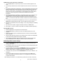
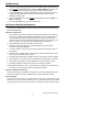
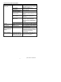
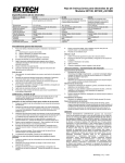
User Manual
Oyster-10 pH/mV/Temperature Meter
Introduction
Congratulations on your purchase of Extech's Oyster Series splash-proof meter. This
microprocessor-based device with tactile buttons simultaneously displays pH or mV and
o
o
Temperature ( C/ F selectable). 25 labeled readings can be conveniently stored for later
recall. The Oyster 10 is battery operated, portable, and includes a hinged display that can be
adjusted to any viewing angle. In addition, the neck-strap offers hands-free operation.
Advanced features include diagnostic displays, MIN/MAX readings, audible alerts, 5-point
buffer recognition, & Auto/Manual temperature compensation. Careful use of this meter will
provide years of reliable service.
Specifications
Range (Resolution)
± 1000 mV DC (1 mV)
mV
Temperature
o
Accuracy
+ 2mV
o
o
o
32.0 to 212.0 F (0.0 to 99.9 C)
+ 0.8 F (0.5 C)
0.00 to 14.00pH (0.01pH)
+ 0.02pH
pH
o
o
Temperature Compensation
32 to 212 F (0-100 C) AUTO or MANUAL modes
Power
9 volt battery or optional AC adapter
Display
Dual LCD display for simultaneous pH or mV and
o
o
temperature readings. LCD viewing angle: 90 to 180
Over-range Indication
Displays " ---- "
Power
9 volt battery or optional AC adapter
Auto Power OFF
After 10 minutes of inactivity
Low Battery Indication
Battery icon appears on LCD
Dimensions / Weight
3.75 x 4.25 x 2" (96 x 108 x 45mm) / 12 oz (340g)
Meter Description
1.
LCD Display
2.
Battery compartment (9V battery)
3.
Function buttons (Power, Up/Down, Max/Min, pH/mV, Store/Recall)
4.
AC Adapter input (117VAC)
5.
RTD Temperature probe input (3.5mm phono jack)
6.
BNC style pH/mV electrode input
7.
Neckstrap loop (2)
1
2
4
5
6
3
7
7
2
Oyster-10, Version 1.7 December 2004
pH Overview
pH is a unit of measure (ranging from 0 to 14pH) indicating the degree of acidity or
alkalinity of a solution. pH tests are the most commonly performed measurements in water
analysis, using the hydrogen ion activity of a solution to determine acidity or alkalinity.
Solutions with a pH less than 7 are considered acidic, solutions with a pH higher than 7 are
known as bases, and solutions with a pH of exactly 7 are considered neutral.
The pH scale is logarithmic, so, for example, if sample A is 1 pH less than Sample B, this
means that Sample A is 10 times more acidic then Sample B. A difference of 1 pH
represents a ten-fold difference in acidity.
ORP/REDOX Overview
ORP stands for Oxidation Reduction Potential and represents the oxidizing or reducing
nature of a solution. The overall “reactive” tendency of a solution can be determined from
ORP measurements. ORP testing is becoming more common in waste-water and water
treatment measurement regimens. The unit of measurement for ORP is mV.
Calibration and Operation
pH Calibration (NOTE: ORP does not require calibration)
Before accurate measurements can be obtained, it is necessary to calibrate the meter with
the electrode. Typically, pH 7 is calibrated first and then one or more of the other buffers
(shown in the left column in the table below). The meter automatically recognizes all of the
buffers listed in the table below and calibrates itself to the buffer’s pH value.
1. Connect the pH electrode to the meter’s BNC connector input.
2. Open the top half of the meter to an appropriate viewing position.
3. Power the meter with the POWER/CAL button.
4. Place the electrode into a buffer solution (4, 7, or 10).
5. Press and hold the CAL key until the CAL display icon appears.
6. During calibration, CAL is shown on the display followed by SA (saved).
7. When calibration is complete, the meter automatically displays END and returns to
normal operation mode. Repeat steps 1-5 as necessary. Note that it is not necessary
to turn the meter off and then back on again to calibration another reference.
Important calibration note: Since pH electrodes can vary in performance, this meter
includes a special feature that displays an electrode’s slope in %. For example, if two
electrodes (one new and moderately used) are calibrated in the same pH 4 solution they’ll
both display pH 4 on the meter. This is because the meter will accept one pH value for a
range of measurement values as shown in the table below (in this case, any reading
between 1.68pH and 6.50pH will be accepted as 4pH calibration). The meter then displays
the slope % for the electrode under test. If the slope % is below 75% or above 125%, the
electrode must be replaced. A slope of 100% is ideal.
pH reading
Range of measurement
1.68
0.00 to 1.68
4.00
1.68 to 6.50
7.00
6.50 to 7.50
10.00
7.50 to 12.45
12.45
12.45 to 14.00
3
Oyster-10, Version 1.7 December 2004
pH Measurement and Temperature Compensation
1. Use the pH/mV button to select the pH mode. The unit of measure appears on the
LCD.
2. Connect the pH electrode to the meter and place the sensor end in the solution under
test.
3. For automatic temperature compensation, connect the temperature probe to the meter
(display will read ATC) and place the sensor end in the solution about 1/3 of the way
below the solution surface. The temperature reading of the solution appears on the
bottom of the LCD. When the temperature of a sample differs from a buffer solution
temperature, allow enough time for the electrode to stabilize to the sample's
temperature.
4. For manual temperature compensation, a temperature sensor is not connected to the
meter (MANUAL is displayed). Adjust the meter’s temperature display with the
up/down buttons so that the displayed temperature matches the temperature of the
solution. A manual thermometer will be needed to determine the solution temperature
first.
5. To change the unit of measure for temperature (C to F or F to C), press and hold the
pH/mV button while powering the meter. The LCD reflects the unit of measure.
6. Read the pH measurement on the main display. An out of range reading is indicated by
dashes ( ----- ).
7. When the test is complete, unplug the electrode and rinse it in distilled water.
8. Place approx. 1 ml of pH 4 solution or tap water in the wetting cap before replacing it.
mV (ORP) Measurements
1. Note that calibration is not required for mV measurements.
2. Use the pH/mV button to select the mV mode. The display will reflect the unit of
measure.
3. Remove the wetting cap from the ORP electrode and connect the cable via the BNC
meter connection.
4. Rinse the ORP electrode and place it into a sample solution. When the LCD stabilizes
it will read the redox potential of the sample in millivolts.
5. When sampling is complete, unplug and rinse the electrode. Place a small portion
(1ml) of distilled water in the wetting cap. Place the cap over the electrode.
25-Reading Measurement Storage
1. Press the STORE/RECALL button to store the current reading. Press each time a
reading is to be stored.
2. If an attempt is made to store more than 25 readings, the stored readings (starting with
the first reading) will be overwritten.
3. To recall readings, press and hold the STORE/RECALL button until the ‘RECALL’ icon
appears on the LCD. Use the up/down arrow buttons to scroll through the stored
readings. Note that ‘NULL’ is displayed if there are no readings in memory.
4. To exit this mode, press and hold the STORE/RECALL button until the ‘RECALL’ icon
disappears.
5. To clear the contents of the memory press and hold the up and the down arrow
buttons while powering the meter on until the ‘CLr’ icon appears on the LCD. All 25
locations will be erased.
Note: Readings are stored in non-volatile memory (saved when the meter is turned off).
4
Oyster-10, Version 1.7 December 2004
MAX/MIN Display
1. The meter memorizes the highest (MAX) and lowest (MIN) readings when prompted.
2. Press and hold the MAX/MIN button until both the MAX and MIN icons appear on the
LCD. The meter will now begin keeping track of the MIN and MAX readings.
3. To view MAX/MIN values, press the MAX/MIN button again; the meter automatically
displays the highest and lowest readings in succession and then returns to the
MAX/MIN recording mode.
4. To exit the MAX/MIN mode, press and hold the MAX/MIN button until the MAX and
MIN icons disappear.
5. To clear the MAX/MIN memory, cycle the meter power.
pH Electrode Model 60120B Operation
The Following information applies to the Epoxy Body, Sealed Reference Combination pH
Electrode Model 60120B.
Electrode Considerations
1. The 60120B pH electrode is recessed in the polymer body allowing it to rest against
the bottom of a beaker without damaging the glass bulb. This eliminates the need for
electrode holders and allows the probe to be used as a stirring rod. This sealed
reference design eliminates the need for adding filling solutions (minimizing "dry-out")
and can be used in up to 100 psig systems without external pressurization.
2. The Electrode should remain in its bottle or cap until used.
3. If bubbles are seen in the bulb area, hold the electrode by its cap and shake
downwards until bubbles disappear.
4. To improve speed of response, vigorously stir the electrode in the sample, buffer, or
rinse solution.
5. After exposure to a sample, buffer, or rinse solution, shake the electrode with a snap
motion to remove residual drops of solution.
6. Use part of the sample/buffer to be tested next as a rinse solution whenever possible.
7. When calibrating, use a buffer as close as possible to the expected pH of the sample.
8. Keep buffers and samples at the same temperature to avoid temperature effects.
9. pH readings stabilize at various rates; allow time for readings to stabilize.
10. Electrodes deteriorate over time. If accuracy falls to 10% (slope), the electrode should
be cleaned. If no improvement is observed, replace the electrode.
Electrode Calibration and Cleaning
Refer to the earlier section ‘Calibration and Operation’ for calibration details. Refer to the
section below ‘Maintenance and Troubleshooting’ for details on electrode cleaning.
Electrode Storage
The electrode can be stored in the soaker bottle or wetting cap. For the storage bottle,
slide the cover onto the electrode, replace the O-ring, and insert electrode into the bottle
firmly tightening the cap. Ensure that the bottle or cap is filled with a pH of 4 buffer solution.
5
Oyster-10, Version 1.7 December 2004
Maintenance and Troubleshooting
Electrode Cleaning
The type of electrode coating that occurs over time will determine the cleaning method.
Soft coatings can be removed by vigorous stirring or by using a squirt bottle. Organic
chemical coating (hard coatings) should be chemically removed. Only in extreme cases
should the bulb be cleaned mechanically.
Battery Replacement
Install a new battery when the low battery indicator appears on the LCD. Remove the
battery cover, install a new 9V battery, and replace the battery cover.
Troubleshooting the Meter
Meters are the least likely cause of pH measurement problems. To rule out the meter
check the following:
1. Check the 9V battery and replace it if necessary.
2. When using the AC adaptor for power, check that the line cord is firmly connected to
the meter.
3. Replace the existing electrode connector with optional BNC shorting plug (shorts the
ground ring to the center pin of the meter’s BNC jack) and check the following:
a) Set the measurement mode to pH. The LCD reading should be stable.
b) Adjust the calibration control for an LCD reading of 7.00.
c) Change to the mV measurement mode. The LCD should read 0 mV.
d) Note that an out of range reading is indicated by dashes ( -------).
6
Oyster-10, Version 1.7 December 2004
Troubleshooting an Electrode Problem
Symptom
Cause
Long response time or Clogged Junction
reading drift
Strong Alkaline
measurement
Deteriorated Gel layer of
pH sensing membrane
Protein coating on
electrode surface
Dry Bulb
Static Charge
Same readings in
different buffers and
samples
Erratic LCD display
Recommended Solution
Soak in 4.07 M Potassium Chloride
o
(KCl) @ 60 C for 30 minutes. Replace
electrode if necessary.
Soak in 0.1 M HCL overnight
Replace electrode
Soak in 1 gm Pepsin dissolved in
100ml of 0.1 m HCL for 30 mins. or as
needed
Oil, paint, dyes, suspended Rinse electrode alternately with
solids on sensor
materials solvent (briefly) then a
buffer 7.00
Organic solvents are
Organic mole fraction has to be less
coating sensor
than 50% to assure reasonable
readings. Limit time of measurement.
Keep probe in the 7.0 buffer between
readings.
Dehydrated membrane
Read solution for dry bulb below
Long term storage without Soak electrode tip in wetting cap filled
wetting
with 1ml 7.00 buffer for 24 to 48 hours
Wiping electrodes
Rinse electrode in 7.0 buffer and blot.
Do no wipe electrode.
Cracked or broken bulb
Replace electrode. Use bulb guard.
Avoid plunging electrode to bottom of
container and spinning bars. A wetting
cap will protect bulb between
measurements.
Samples have low ionic
For each 50 ml of sample add 1 drop
strength (lacks salt); e.g.
(50uL) of SAT.KCL No alteration in
distilled, de-ionized, boiled, pH will occur by inert KCL.
lake water (high pressure)
7
Oyster-10, Version 1.7 December 2004
Calibration and Repair Services
Extech offers complete repair and calibration services for all of the products we sell.
For periodic calibration, NIST certification or repair of any Extech product, call customer
service for details on services available. Extech recommends that calibration be performed
on an annual basis to ensure calibration integrity.
WARRANTY
EXTECH INSTRUMENTS CORPORATION warrants the basic instrument to be free of
defects in parts and workmanship for one year from date of shipment (a six month limited
warranty applies on sensors and cables). If it should become necessary to return the
instrument for service during or beyond the warranty period, contact the Customer Service
Department at (781) 890-7440 EXTENSION 210 for authorization or visit www.extech.com for
more information. A Return Authorization (RA) number must be issued before any
product is returned to Extech. The sender is responsible for shipping charges, freight,
insurance and proper packaging to prevent damage in transit. This warranty does not apply
to defects resulting from action of the user such as misuse, improper wiring, operation
outside of specification, improper maintenance or repair, or unauthorized modification. Extech
specifically disclaims any implied warranties or merchantability or fitness for a specific
purpose and will not be liable for any direct, indirect, incidental or consequential damages.
Extech's total liability is limited to repair or replacement of the product. The warranty set forth
above is inclusive and no other warranty, whether written or oral, is expressed or implied.
Support line (781) 890-7440
Technical support: Extension 200; E-mail: [email protected]
Repair & Returns: Extension 210; E-mail: [email protected]
Product specifications subject to change without notice
For the latest version of this User’s Guide, Software updates, and other
up-to-the-minute product information, visit our website: www.extech.com
Copyright © 2004 Extech Instruments Corporation.
All rights reserved including the right of reproduction in whole or in part in any form.
8
Oyster-10, Version 1.7 December 2004