1
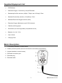
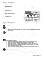
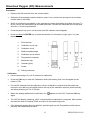
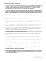
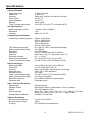
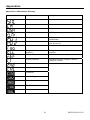
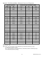
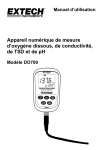
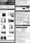
User's Guide
Digital Dissolved Oxygen,
Conductivity, TDS and pH Meter
Model DO700
Introduction
Congratulations on your purchase of the Extech DO700 meter. For best results, please read the
entire manual before use. The DO700 measures Dissolved Oxygen (DO), Conductivity, pH, mV,
and temperature parameters. Conductivity measurements also yield TDS (total dissolved solids),
Salinity, and Resistivity readings.
The built-in microprocessor provides automatic calibration, automatic temperature compensation,
data storage, and self-diagnostics. The digital filter improves measurement speed and accuracy.
The meter offers a backlit LCD display and is dust-proof and waterproof, meeting IP57.
This meter is shipped fully tested and calibrated and, with proper use, will provide years of reliable
service.
pH Features
The meter can recognize up to 13 types of pH standard buffer solutions. Two special pH modes
(for distilled water and distilled water mixed with ammonia) are provided. These special modes
offer general slope compensation and non-linearity solution temperature compensation suitable
for the electric power and petrochemical industries.
Conductivity Features
Automatic frequency conversion and voltage regulation increases the Conductivity electrode
range (K = 1 to 10 times). One point Conductivity calibration allows measurements from 0 to
100mS/cm. Up to 8 types of Conductivity standards can be recognized.
The meter has an automatic range feature with non-linear temperature compensation for distilled
water with Conductivity values lower than 10uS/cm greatly improving accuracy and suitable for
the microelectronics and pharmaceutical industries.
Dissolved Oxygen Features
The latest technology DO electrode offers a temperature and salinity sensor with automatic
temperature compensation and automatic salinity compensation as well as manual barometric
pressure compensation.
2
DO700-EU-EN-V2.1-5/11
Supplied Equipment List
•
DO700 Meter
•
Dissolved Oxygen, Conductivity, and pH Electrode
•
Standard pH buffer solutions (4.00pH, 7.00pH, and 10.01pH) / 50ml
•
Standard Conductivity solution (1413µS/cm) / 50ml
•
Standard Dissolved Oxygen solution (30ml)
•
Dissolved Oxygen Membrane cap for DO electrode
•
Cathode polishing paper
•
Screwdriver (for removing battery compartment cover)
•
Batteries (2 x ’AA’ 1.5V)
•
User’s Guide
•
Carrying Case
Meter Description
1. LCD Display (detailed in section below)
2. Rubber protective jacket (remove to access the rear battery compartment)
3. Keypad (detailed in section below)
4. Electrode connection jack
5. Electrode plug
6. Electrode cable
3
DO700-EU-EN-V2.1-5/11
Display Description
1. Measurement type icons
2. Measured reading
3. 888 (Stored data serial number), M+ (measurement to be stored icon), RM (reading to be
recalled icon)
4. Units of measure
5. Temperature reading
6. Stable measurement icon
7. Calibration icons
8. Low battery icon
Keypad Description
ON/OFF Power Key
Calibration Key
a) When taking a measurement, press this key to enter the calibration mode
b) When in the programming mode, press this key to change the displayed number or the
ON/OFF state
Mode Key
a) In pH measuring mode, one short press switches between pH and mV measuring
modes. One long press (>2s) enters the parameter setting mode. Subsequent presses
will scroll through the available parameters.
b) In other measuring modes, press to enter the parameter setting modes. The meter will
scroll through the available parameters
Backlight and ENTER Key
a) In the measurement mode, momentary presses toggle the backlight on and off
b) When in the programming or calibration mode, press to ENTER data
c) When in the pH mode, press and hold to change the resolution 0.01 to 0.1pH
d) When in the Conductivity mode, press and hold to scroll through the TDS, Salinity,
Resistivity, and Conductivity modes
e) When in DO mode, press and hold to select the unit of measure (mg/L > ppm > %).
Release the key when the desired unit is displayed
MEMORY STORE and RECALL Key
a) In the measurement mode, momentary presses store the displayed readings. Press and
hold for at least 2 seconds to recall a saved reading
b) In programming mode, press to change the displayed number or ON/OFF state
4
DO700-EU-EN-V2.1-5/11
Store, Recall, and Clear Datalogger Memory
STORE Readings
The meter can store up to 100 DO, 100 pH, 100 mV, and 100 Conductivity readings for a total of
400 data points. To store a reading, wait until the reading stabilizes (the smiling face icon
appears when the reading stabilizes). Press the M+/RM key momentarily to store a reading. The M+
icon appears and the data point serial number increments.
RECALL Readings
In the measurement mode, press the M+/RM key to recall the most recently stored reading. RM and
the data point serial number for the displayed reading will appear on the LCD. The measurement
information will appear on the lower right hand side of the LCD. Use the CAL or M+/RM buttons to
scroll the remaining stored readings. Press the ENTER key to return to the normal measurement
mode.
CLEAR Readings
From the RECALL mode, press and hold the ENTER key for at least five (5) seconds. The LCD
display will show ‘CLR’ indicating that all of the stored readings have been erased. The unit will
automatically return to the normal measurement mode after approximately 2 seconds.
5
DO700-EU-EN-V2.1-5/11
pH Measurement Mode
Preparation for Measurement
1. Unscrew the protective cap on the probe jack located on the bottom of the meter (store the
protective cap in the carrying case for later use).
2. Carefully connect the pH probe to the meter’s probe jack. The probe can only be inserted in one
orientation. Once it is firmly connected, screw the probe collar onto the meter to secure the
probe.
3. Turn the meter on using the power key
.
4. Press the MODE key momentarily to switch to the pH mode only if the meter is in the mV mode.
Otherwise, the unit of measure should already display pH units.
3-Point Calibration (7.00pH, 4.00pH and 10.01pH)
1. Press the CAL key to enter the Calibration mode. The meter’s display will show a blinking ‘C1’
2. Rinse the probe in distilled water, allow it to dry, and submerge it into a pH 7.00 buffer solution.
Stir the solution briefly and allow it to stay in the buffer solution until a stable reading is reached
3. Press CAL again and the display will show a blinking ‘7.00’
4. This portion of the calibration procedure is complete when the display stops blinking and shows
the ‘C2’ icon. The unit will automatically switch to the second point of the calibration
5. Rinse the probe in distilled water again, allow it to dry, and submerge it into a pH 4.00 buffer
solution. Stir the solution briefly and allow it to stay in the buffer solution until a stable reading is
reached
6. Press CAL again and the display will show a blinking ‘4.00’
7. This portion of the calibration procedure is complete when the display stops blinking and shows
the ‘C3’ icon. The unit will automatically switch to the third point of the calibration
8. Rinse the probe in distilled water again, allow it to dry, and submerge it into a pH 10.01 buffer
solution. Stir the solution briefly and allow it to stay in the buffer solution until a stable reading is
reached
9. Press CAL again and the display will show a blinking ‘10.01’
10. After the display stabilizes the 3-point calibration icon will appear
1-Point and 2-Point Calibration
A one or two point calibration is acceptable if the expected measurement result is known.
For example, if the expeced pH is 4pH, it is acceptable to perform only a 1-Point Calibration (4pH).
If the expected measurement is between 4.00pH and 7.00pH, the user can perform a 2-Point
Calibration (4.00 and 7.00pH), and so on.
For a 4pH calibration, only the circled L will appear on the LCD. For a 7.00pH, only the circled M will
appear on the LCD. For a 10.01pH Calibration, only the circled H will appear (Low, Medium, and
High).
For all other applications, a 3-Point Calibration is recommended. Always perform a 3-Point
Calibration on new probes and probes that have been in use for long periods. This maximizes
measurement slope linearity.
Press the ENTER key to exit the Calibration mode.
6
DO700-EU-EN-V2.1-5/11
Testing the pH of a Sample
1. Perform the pH Calibratoin as described above
2. Rinse and dry the pH Probe and submerge it in a sample liquid
3. Stir the solution briefly with the probe and allow it to stand until the display stabilizes
4. Note that the closer the temperature of the sample solution to the calibration solution, the more
accurate readings
Programming pH Parameters
The Table below shows the available programming menu items P1 ~ P7. Each parameter is
explained in detail in the subsequent sections.
Parameters
P1
P2
P3
Code
sol
pH buffer solution series selection
Distilled water pH temperature
compensation setting (see notes
below this Table)
Distilled water with Ammonia pH
temperature compensation setting
(see Notes below this Table)
Selections
USA (Europe &
U.S.A)
NIS (NIST)
CH (China)
OFF / ON
OFF / ON
P4
Temperature unit setting
℃/℉
P5
Back light display time setting
0-1-3-6min
P6
Auto power off setting
0-10-20min
P7
Restore to default factory settings
OFF / ON
Notes on P2 and P3 Parameters: Measurements of distilled water and distilled water mixed with
ammonia affect the temperature compensation and the slope linearity of the pH probe. Such
measurements are sometimes used in the electrical power and petrochemical industries. Set these
parameters to ON only if necessary, otherwise leave these parameters in the OFF state.
7
DO700-EU-EN-V2.1-5/11
Parameter P1 (pH Buffer Solution Setting)
1. From the pH measurement mode, press and hold MODE for at least 2 seconds and then
release, the ‘P1’ icon appears on the LCD.
2. Use the CAL or the M+/RM keys to toggle through the three (3) selections: USA (for use in the
USA or Europe, NIS (for NIST calibration purposes), and CH (for use in China).
3. Momentarily press MODE to move to the next parameter (P2), or press ENTER to return to the
normal measurement mode.
Parameter P2 (Distilled Water Temperature Compensation Setting)
1. From the P2 menu, use the CAL or the M+/RM keys to turn this feature ON or OFF.
2. Momentarily press MODE to move to the next parameter (P3), or press ENTER to return to the
normal measurement mode.
Parameter P3 (Distilled Water with Ammonia Temperature Compensation Setting)
1. From the P3 menu, use the CAL or the M+/RM keys to turn this feature ON or OFF.
2. Momentarily press MODE to move to the next parameter (P4) or press ENTER to return to the
normal measurement mode.
Parameter P4 (Temperature Measurement Units Setting)
1. From the P4 menu, use the CAL or the M+/RM keys to turn this feature ON or OFF.
2. Momentarily press MODE to move to the next parameter (P5) or press ENTER to return to the
normal measurement mode.
Parameter P5 (Display Backlight Setting)
1. From the P5 menu, use the CAL or the M+/RM keys to select 0, 1, 3, or 6 minute default
backlighting time.
2. Momentarily press MODE to move to the next parameter (P6) or press ENTER to return to the
normal measurement mode.
Parameter P6 (Automatic Power OFF Setting)
1. From the P6 menu, use the CAL or the M+/RM keys to select a 0, 10, or 20 minute Auto Power
OFF time.
2. Momentarily press MODE to move to the next parameter (P7) or press ENTER to return to the
normal measurement mode.
Parameter P7 (Restore Factory Default Settings)
1. From the P7 menu, use the CAL or the M+/RM keys to select ON (reset the factory default
settings) or OFF (cancel edit).
2. Momentarily press MODE to move to the first parameter (P1) or press ENTER to return to the
normal measurement mode.
8
DO700-EU-EN-V2.1-5/11
pH Measurement, Calibration, and Electrode Considerations
•
Error messages ERR-1: Electrode zero potential error and ERR-2: Electrode slope error; For
either error, check the following:
1. Air bubbles in the electrode bulb. Shake rigorously to remove air bubbles
2. Accuracy of the pH buffers used in calibration. Replace buffers if necessary
3. Set meter to its factory default state in Parameter P7 (previous section of manual)
•
Calibration intervals depend on the sample, the electrode performance, and the required
accuracy. For high accuracy measurements (≤ ±0.02pH), the meter should be calibrated
immediately before taking a measurement. For general accuracy (≥±0.1pH), the meter can be
calibrated and used for approximately one week before the next calibration.
•
The meter must be recalibrated in the following situations:
1. New probe, or probe that is unused for a long period of time
2. After measuring acids (pH<2) or alkaline solutions (pH>12)
3. After measuring a solution that contains fluoride or a concentrated organic solution
4. If the solution’s temperature differs widely from the calibration solution temperature
•
The soaking solution contained in the supplied protective bottle is used to maintain activation in
the glass bulb and junction. Loosen the capsule, remove the electrode and rinse in distilled
water before taking a measurement. Insert the electrode and tighten the capsule after
measurements to prevent the solution from leaking. If the soak solution is turbid or moldy,
replace the solution.
•
To prepare a soak solution: Use 25g pure KCL dissolved with purified water and diluted to
100mL. The electrode should not be soaked in a distilled water protein solution or an acid
fluoride solution for long periods of time. In addition, do not soak the electrode in organic silicon
lipids.
•
For calibration accuracy, the pH of the standard buffer solution must be reliable. The buffer
solution should be refreshed often, especially after heavy use.
•
For best accuracy, always keep the meter clean and dry, especially the meter’s electrode and
electrode jack. Clean with medical cotton and alcohol if necessary.
•
The sensitive glass bulb at the front of the combination electrode should not come in contact
with hard surfaces. Scratches or cracks on the electrode will cause inaccurate readings. Before
and after each measurement, the electrode should be washed with distilled water and dried. Do
not clean the glass bulb with a tissue for it will affect the stability of the electrode potential and
increase the response time. The electrode should be thoroughly cleaned if a sample sticks to
the electrode. Use a solvent if the solution does not appear clean after washing.
•
Electrodes that have been used over a long period of time, used in a strong solution that has
damaged the sensitive bulb, or used with a substance resulting in a jam at the junction will be
become passivated; the sensitivity will decrease, its response will slow, and the readings will be
inaccurate. Replace the electrode as soon as possible in these cases.
•
For abnormal readings, try calibrating again; if the problem persists replace the Electrode. The
user can also try resetting the meter to factory default conditions per Parameter P7 (detailed in
an earlier section). Electrode life can be shortened by heavy use, extreme conditions, and
improper maintenance.
9
DO700-EU-EN-V2.1-5/11
mV Measurement Mode
1.
Unscrew the protective cap on the probe jack located on the bottom of the meter (store the
protective cap in the carrying case for later use).
2.
Carefully connect the pH probe to the meter’s probe jack. The probe can only be inserted in
one orientation. Once it is firmly connected, screw the probe collar onto the meter to secure
the probe.
.
3.
Turn the meter on using the power key
4.
Press the MODE key momentarily to switch to the mV mode.
5.
Immerse the electrode in the sample solution, slowly stir the solution with the electrode and
then allow it to rest in the solution.
6.
When the smile face icon
appears on the LCD, the reading has stabilized.
mV Programming Parameters
Prompt
Parameters
Code
Settings
P1
Back light display time
0 -1-3-6 min
P2
Auto power off time
0 -10-20 min
Parameter P1 (Display Backlight Setting)
1.
Press MODE to access the P1 Parameter.
2.
Use the CAL or the M+/RM keys to select 0, 1, 3, or 6 minute default backlighting time.
3.
Momentarily press MODE to move to the next parameter (P2) or press ENTER to return to
the normal measurement mode.
Parameter P2 (Automatic Power OFF Setting)
1.
From the P2 menu, use the CAL or the M+/RM keys to select a 0, 10, or 20 minute Auto
Power OFF time.
2.
Momentarily press MODE to move back to Parameter P1, or press ENTER to return to the
normal measurement mode.
10
DO700-EU-EN-V2.1-5/11
Conductivity Measurement Mode
Preparation for Measurement
1. Unscrew the protective cap on the probe jack located on the bottom of the meter (store the
protective cap in the carrying case for later use).
2. Carefully connect the electrode to the meter’s input jack. The electrode can only be inserted in
one orientation. Once it is firmly connected, screw the electrode collar onto the meter to secure
it.
3. Turn the meter on using the power key
.
4. Press and hold the ENTER key to select the desired mode: Conductivity, TDS (Total Dissolved
Solids), Salinity, or Resistivity.
Calibration
1. Press the CAL key and ‘CAL’ will appear flashing on the LCD.
2. Clean and dry the conductivity electrode (use distilled water to clean).
3. Immerse the electrode in the 1413μS/cm calibration solution.
4. Stir the solution with the electrode and allow it to rest in the solution until the stabilize icon (
appears.
)
5. Press CAL again and the display will flash ‘1413μS/cm’; After several seconds the ‘END’ icon
will appear and the meter will return to the measuring mode.
6. The LCD will display the icon ‘M’, indicating that the calibration is complete.
7. If the measurement value is unstable, repeat the calibration until the measurement is stable.
Replace the electrode if necessary.
Notes: The meter is calibrated before leaving the factory and can generally be used right out of
the box. The meter can only be calibrated in the Conductivity mode and not from the TDS,
Salinity, or Resistivity modes.
Measuring the Conductivity of a Sample
1. Clean and dry the conductivity electrode and immerse in the sample solution.
2. Stir the solution and allow the electrode to rest in the solution until the reading stabilizes (smile
face icon appears).
3. Read the conductivity measurement on the meter’s display.
5. Press and hold the ENTER key to select TDS (Total Dissolved Solids), Salinity, Resistivity, or
Conductivity measurement modes.
Calibration Considerations
This meter offers two calibration solution series (configurued in Parameter P1).
(a) (Europe & U.S.A. series) — 84μS/cm, 1413μS/cm, 12.88 mS/cm and 111.9 mS/cm
(b) (China series) — 146.6μS/cm, 1408μS/cm, 12.85mS/cm and 111.3 mS/cm
The DO700 offers a unique one-point calibration feature. The user can select the calibration solution
closest to the expected measuremnt value. In general the most common calibration solution is 1413
μS/cm. Use the supplied conductivity electrode (K = 1 cm-1), and perform the calibration using the
supplied 1413 μS/cm calibration solution. The meter can then be used for measurements below 100
mS/cm. Please refer to the chart below.
11
DO700-EU-EN-V2.1-5/11
Measuring range
0.05 to 20μS/cm
Electrode constant
K=0.1cm
Calibration solution
84μS/cm
-1
0.5μS/cm to 200mS/cm
(flow test)
K=1.0cm
84μS/cm
-1
1413μS/cm
12.88 mS/cm
111.9 mS/cm
Calibration indicator
L
L
M
H
There are two electrode calibration methods: Standard Solution calibration and Constant calibration.
The calibration described above in the section Calibration refers to the Standard Solution method
(the most accurate calibration method, assuming the calibration buffer standard is accurate and
fresh).
To select the Constant calibration method use Parameter P5 described below in the Programming
Parameters – Conductivity section.
The temperature compensation coefficient of the meter setting is 2.0%. However, the conductivity
temperature coefficient is different for solutions of a different variety and concentration. Use the
chart below for common solution types (use Parameter P4 as described below in the Programming
Parameters – Conductivity section).
The meter can perform an automatic non-linear temperature compensation in distilled water for
readings below 10 μS/cm.
Note: When the coefficient for the temperature compensation is set to 0.00 (no compensation), the
measurment value will be based on the current temperature.
Solution
Temperature compensation
coefficient
NaCl salt solution
2.12%
5%NaOH solution
1.72%
Dilute ammonia solution
1.88%
10% hydrochloric acid solution
1.32%
5% sulfuric acid solution
0.96%
Important Note: When one or more of the programmable parameters is changed by the user from
its original factory default condition, the parameter’s code shown below, is displayed in the upper
right corner of the display as shown in diagram below (in this case, Parameter P Tcc). If more than
one parameter is changed, only the code from the first parameter change is displayed.
12
DO700-EU-EN-V2.1-5/11
Programming Parameters - Conductivity
The Table below shows the available programming menu items P1 ~ P9. Each parameter is
explained in detail in the subsequent sections.
Parameters
Code
Selections
P1
Standard solution series selection
sol
USA (Europe & U.S.A)
CH (China)
P2
Electrode Constant selection
0.1, 1, or 10
P3
Reference Temperature selection
77, 68, and 64 F (25,
20,and 18 ℃)
P4
Temperature compensation
coefficient setting
0.00 to 9.99%
P5
Electrode Constant Calibration
P6
Temperature units
℃℉
P7
Back light display time setting
0-1-3-6min
P8
Auto power off setting
0-10-20min
P9
Restore to default factory settings
OFF / ON
o
Parameter P1 (Conductivity Solution Setting)
1. From the Conductivity mode, press the MODE key, the ‘P1’ icon appears on the LCD.
2. Use the CAL or the M+/RM keys to toggle through the two (2) selections: USA (for use in the
USA or Europe) and CH (for use in China).
3. Momentarily press MODE to move to the next parameter (P2), or press ENTER to return to the
normal measurement mode.
Parameter P2 (Electrode Constant ‘K’ Selection)
1. From the P2 menu, use the CAL or the M+/RM keys to select the desired electrode constant
(0.1, 1.0, or 10). The default setting is K=1.0.
2. Momentarily press MODE to move to the next parameter (P3), or press ENTER to return to the
normal measurement mode.
13
DO700-EU-EN-V2.1-5/11
Parameter P3 (Reference Temperature Selection)
1. From the P3 menu, use the CAL or the M+/RM keys to select the desired reference temperature
(25, 20, or 18℃).The default setting is 25℃
2. Momentarily press MODE to move to the next parameter (P4) or press ENTER to return to the
normal measurement mode
Parameter P4 (Temperature Coefficient Temperature Compensation Setting)
1. From the P4 menu, use the CAL or the M+/RM keys to select the coefficient in percent from
0.00 to 9.99. When set to zero, the temperature compensation is turned OFF. The default
setting is 2.0%
2. Momentarily press MODE to move to the next parameter (P5) or press ENTER to return to the
normal measurement mode
Parameter P5 (Electrode Constant calibration)
1. In the P5 window the user can see the existing constant in the main measurement area of the
-1
LCD in cm units
2. From the P5 menu, use the CAL or the M+/RM keys to change the constant to match the
constant printed on the electrode housing
3. Momentarily press MODE to move to the next parameter (P6) or press ENTER to return to the
normal measurement mode
Parameter P6 (Temperature units of measure)
1. From the P6 menu, use the CAL or the M+/RM keys to select the desired unit of measure (C or
F)
2. Momentarily press MODE to move to the next parameter (P7) or press ENTER to return to the
normal measurement mode
Parameter P7 (Display Backlight Setting)
1. From the P7 menu, use the CAL or the M+/RM keys to select 0, 1, 3, or 6 minute default
backlighting time
2. Momentarily press MODE to move to the next parameter (P8) or press ENTER to return to the
normal measurement mode
Parameter P8 (Automatic Power OFF Setting)
1. From the P8 menu, use the CAL or the M+/RM keys to select a 0, 10, or 20 minute Auto Power
OFF time
2. Momentarily press MODE to move to the next parameter (P9) or press ENTER to return to the
normal measurement mode
Parameter P9 (Restore Factory Default Settings)
1. From the P9 menu, use the CAL or the M+/RM keys to select ON (reset the factory default
settings) or OFF (cancel edit). Note that the instant the ON selection is made the meter will
revert to its factory default state and all user settings will be cleared. Only select ON if absolutely
necessary.
2. Momentarily press MODE to move to the first parameter (P1) or press ENTER to return to the
normal measurement mode
14
DO700-EU-EN-V2.1-5/11
Conductivity Measurement, Calibration, and Maintenance Considerations
•
The meter and probe are calibrated before leaving the factory; the user can take measurements
immediately upon receiving the unit.
•
The recommend calibration period is once per month under normal circumstances; It is
necessary to calibrate a newly purchased conductivity electrode or one that has been in service
for a long period of time.
•
Keep the conductivity electrode clean. It’s best to rinse electrodes with the sample solution.
•
The surface of the supplied conductivity electrode is plated with a layer of platinum (black) in
order to lower the electrode polarization and increase the measuring range. Do not polish the
black platinum surface; clean it by stirring in Distilled water. If excessive organic buildup appears
on the black platinum coating clean with hot water and detergent or with alcohol.
•
Replace the electrode if the above cleaning methods are ineffective.
•
Reset the meter to its factory default settings (Parameter P9) if unusual operation is noticed. If
the reset process does not solve the issue, return the unit for an evaluation.
15
DO700-EU-EN-V2.1-5/11
Dissolved Oxygen (DO) Measurements
Preparation
•
Remove the DO electrode from the solution bottle.
•
Determine if the sponge inside the bottle is moist. If not, moisten the sponge but do not allow
excess water in the bottle.
•
Small air bubbles are acceptable in the electrode but larger air bubbles should be removed. To
do so, remove the membrane cap and add electrolyte. Connect the electrode to the meter and
allow for a 15-minute polarization.
•
Press the power key to turn on the meter (the DO indicator should appear).
•
Press and hold the ENTER key to select the desired unit of measure (mg/L, ppm, %); then
release.
1.
DO electrode
2.
Calibration cover cap
3.
Calibration cover
4.
Water soaked sponge
5.
Calibration cover bottom
6.
Temperature electrode
7.
Membrane cap
8.
Cathode (gold)
9.
Anode
10. Salinity electrode
Calibration
•
Use the percentage (%) unit of measure for calibration.
•
Press the CAL key to enter the Calibration mode (the flashing CAL icon will appear on the
meter’s LCD).
•
Put the DO electrode into the calibration solution (calibration container that the probe was
housed in upon delivery) and tightly secure the cap of the calibration solution, place vertically
and allow polarizing for 3 to 5 minutes.
•
When the reading stabilizes the smile face icon
again.
•
The LCD will display a flashing ‘100%’ indicating that the calibration is complete. After several
seconds the meter will display ‘END’ and return to the measuring mode.
•
If the displayed reading does not stabilize, polarize again per the Preparation section above,
and retry this calibration procedure.
16
appears on the LCD. Press the CAL key
DO700-EU-EN-V2.1-5/11
Dissolved Oxygen Water Sample Test
•
To measure moving water (water sample velocity of flow >5cm/s) insert the DO electrode into
the water. The water surface should cover the electrode’s thermistor (temperature sensor). The
recommended electrode orientation with regard to the water is a 45°to 75°angle. Move the
electrode around in the water and allow 3 to 5 minutes to take the reading.
•
To measure in static water: Insert the DO electrode into water, water surface should cover the
location of the electrode’s thermistor (temperature sensor), the direction for the electrode with
respect to the water is a 45°to 75°angle. Quickly stir the electrode in water at a speed >5cm/s.
Allow 3 to 5 minutes while taking the reading.
•
To test in slower flowing water: Use the first method above but stir the electrode faster in the
water.
Dissolved Oxygen Measurement and Calibration Considerations
•
The air temperature and water temperature should be within 10 degrees C, if the temperature
difference is greater, please immerse the electrode in the sample water for 10 minutes and then
calibrate.
•
After each start-up, the electrode must be polarized and a calibration must be performed; do not
turn the meter OFF (when in the DO mode, the default auto power off time is zero).
•
During DO tests, the temperature affects the measurement greatly. The electrode’s thermistor
should come in direct contact with the water sample. Please allow 3 to 5 minutes for the
thermistor to gage a stable temperature measurement.
•
DO measurements are also greatly affected by Barometric pressure. The DO700 meter has an
automatic Barometric pressure compensation function.
•
The DO electrode must not be left static in the test solution. Always stir the electrode in the
solution.
•
When measuring, remove air bubbles from the solution under test otherwise measurement
accuracy will be compromised.
•
Small air bubbles in the electrode’s electrolyte are acceptable; however larger bubbles must be
removed.
•
Keep the surface of the DO electrode moist to protect the cathode electrolyte. The supplied
storage sponge should always be kept moistened for proper storage.
•
The salinity electrode is installed in the DO electrode. Its surface is plated with a layer of
platinum (black) to reduce electrode polarization. This surface must not be rubbed or wiped
(clean by swirling it in water). Wash organic matter off of the surface with lukewarm water
containing detergent or use alcohol if necessary.
•
For any display abnormalities while measuring or calibrating, set the meter to its factory default
settings using parameter P7 (explained in next section). If abnormalities persist, the electrode
most probably needs replacing.
17
DO700-EU-EN-V2.1-5/11
Parameter Settings
Prompt
Parameters
Code
Selections
P1
Resolution selection
0.01/0.1(mg/L and ppm)
0.1/1(%)
P2
Salinity calibration
P3
Barometric pressure setting
P4
Temperature unit setting
P5
Back light display time setting
0-1-3-6 min
P6
Auto power off time setting
0-10-20 min
P7
Restore to producer setting
OFF-On (shut-set)
Refer to explanation below
66 to 200kPa
o
o
C/ F
P1 - Resolution selection
•
Press the MODE key to enter the P1 parameter mode.
•
Use the CAL key to select the resolution: 0.01→0.1;
•
Press the MODE key to enter into the next parameter setting or press ENTER to return to
the normal measurement mode.
P2 - Salinity Auto-Compensation
•
From the P1 parameter, press the MODE key to enter P2.
•
Immerse the DO electrode in the 12.88mS/cm calibration solution (the solution level should
cover the electrode). After stirring, allow the electrode to rest in the solution and press the
CAL key. When the value stabilizes, the smile face icon appears on the LCD along with a
flashing “12.9”. The calibration will finish after several minutes and will display a stable
value.
•
Press the MODE key to enter the next parameter or press ENTER to confirm and return to
the measuring mode.
P3 – Manual Barometric Pressure setting
•
From P2, press the MODE key to enter P3, the LCD will display the current barometric
pressure value (unit of measure is kPa), for example, 101.3kPa.
•
Use the CAL or RM key to change the setting (refer to the standard Barometric pressure
table). Press and hold CAL or RM to quickly scroll the value.
•
Press MODE to move to the next parameter or press ENTER to confirm and return to the
measuring mode.
18
DO700-EU-EN-V2.1-5/11
P4 - Temperature unit of measure selection
o
o
•
Use the CAL or the M+/RM keys to select the desired unit of measure ( C or F).
•
Momentarily press MODE to move to the next parameter or press ENTER to return to the
normal measurement mode.
P5 - Display Backlight Setting
•
Use the CAL or the M+/RM keys to select 0, 1, 3, or 6 minute default backlighting time.
•
Momentarily press MODE to move to the next parameter or press ENTER to return to the
normal measurement mode.
P6 - Automatic Power OFF Setting
•
Use the CAL or the M+/RM keys to select a 0, 10, or 20 minute Auto Power OFF time.
•
Momentarily press MODE to move to the next parameter or press ENTER to return to the
normal measurement mode.
Note: The default setting for DO is 0, that is, the auto power off function is defeated.
P7 - Restore Factory Default Settings
•
Use the CAL or the M+/RM keys to select ON (reset the factory default settings) or OFF
(cancel edit).
•
Momentarily press MODE to move to the first parameter (P1) or press ENTER to return to
the normal measurement mode.
Replacing the Membrane Cap
Replace the Membrane cap under the following conditions:
•
Electrode response time increases.
•
Displayed value appears incorrect or abnormal.
•
Damaged or cracked membrane.
Replace as follows:
1. Loosen and then remove the membrane cap.
2. Clean the electrode (without membrane cap) with distilled water and shake the water off
of the electrode.
3. Lightly polish the cathode surface (gold) with a piece of clear velvet or tissue.
4. Slowly inject electrolyte into a new membrane cap. After injecting, check the electrolyte
for air bubbles. If air bubbles are present, carefully tap the membrane cap to remove the
air pockets.
5. Place the membrane cap on a clean surface and place the electrode in the cap
vertically. Slowly twist in a clockwise motion until electrode is tightly attached. Excess
electrolyte may be displaced, wipe excess electrolyte with tissue and distilled water.
6. Check that there are no air bubbles present in the electrolyte (smaller air bubbles are
acceptable). If large air bubbles are present, re-assembly will be required.
7. Do not touch the sensitive membrane when using the electrode or replacing the
membrane cap. Oils from the skin will affect the quality of the membrane and decrease
the rate of oxygen permeability.
19
DO700-EU-EN-V2.1-5/11
Zero Dissolved Oxygen Calibration
The meter receives a zero oxygen calibration before leaving the factory and only requires a zero
oxygen calibration when the electrode (or the electrode cap) is replaced or has been in use for a
relatively extended period of time (6 months or longer). To perform a zero oxygen calibration:
1.
Prepare 100mL of anaerobic water: In a 100 mL beaker add 5g anhydrous sodium sulfite
(Na2SO3) to 100 mL distilled water. Stir to dissolve. The anaerobic water will be usable in
24 hours.
2.
Polarize the DO electrode by connecting it into meter for 15 minutes and then perform a
standard calibration as described in the calibration section earlier in this manual.
3.
Place the electrode in the anaerobic water and press the CAL key to enter the calibration
mode. When the displayed value is ≤ 0.15mg/L (≤5min) press the ENTER key.
4.
If the displayed value is ≤0.02mg/L (within 5 minutes), this indicates that the response time
and the residual current are normal and there is no need to perform the zero oxygen
calibration, press the ENTER key to the normal operating mode.
5.
If the displayed value is >0.15 mg/L after 5 minutes, this indicates that the response time of
the meter is too slow and there is too much residual current. In this case, replace the
membrane cap or remove the membrane cap and use the supplied polishing paper to lightly
wipe the gold plane’s cathode (the surface along the gold-polished arc) and clean the
surface of the cathode with a soft cloth or tissue. Clean the electrode with distilled water and
shake off the excess water. Add some electrolyte to the membrane cap, re-assemble, and
then perform a full scale and a zero oxygen calibration.
Salinity Calibration
Under normal circumstances, a salinity calibration is not required. The meter is equipped with an
automatic salinity compensation; In addition, a salinity calibration has been performed at the
factory prior to shipment; however a salinity calibration is required when the electrode is replaced
or has been in service for a relatively extended period of time. Refer to parameter P2 in previous
section for calibration procedure.
Barometric Pressure Setting
The meter is equipped with a manual barometric pressure adjustment. It is recommended that the
value be set according to the standard barometric pressure table when there is an excessive
change in barometric pressure while using meter. This ensures the accuracy of the barometric
pressure compensation. To change the barometric value refer to parameter P3 in the previous
section. Use the Table in Appendix C for barometric pressure values.
You, as the end user, are legally bound (EU Battery ordinance) to return all used
batteries, disposal in the household garbage is prohibited! You can hand over your
used batteries / accumulators at collection points in your community or wherever batteries
/ accumulators are sold!
Disposal: Follow the valid legal stipulations in respect of the disposal of the device at the
end of its lifecycle
20
DO700-EU-EN-V2.1-5/11
Specifications
pH Specifications
Measuring range
Resolution
Accuracy
Input current
Input impedance
Stability
Temp. Compensation range
-2.00 to 19.99 pH
0.1/0.01 pH
Meter only: ±0.01pH; with probe: ±0.02pH
-12
≤2×10 A
12
≥1×10 Ω
±0.01 pH/3h
o
o
0 to 100 C (32 to 212 F); Automatic (ATC)
mV Specifications
Measuring range (mV/EH)
Resolution
Accuracy
-1999 mV to 0 to 1999mV
1mV
Meter: ±0.1% FS
Conductivity Specifications
Conductivity measuring ranges
TDS measurement range
Salinity measurement range
Resistivity
Resolution
Accuracy
Electrode constant
Reference temperatures
Temp. Compensation range
0.00 to 19.99 µS/cm
20.0 to 199.9 µS/cm
200 to 1999 µS/cm
2.00 19.99 mS/cm
20.0 to 199.9 mS/cm
0 to 100 g/L (TDS: Total Dissolved Solids)
0 to 100 ppt
0 to 100 Mohms
0.01/0.1/1 µS/cm and 0.01/0.1mS/cm
Meter only: ±1% F.S.; with probe: ±2% F.S.
-1
0.1 / 1 / 10 cm
o
o
25, 20, and 18 C (77, 68, and 64 F)
o
o
0 to 50 C (32 to 122 F); Automatic (ATC)
Dissolved Oxygen
Measuring range
Resolution
Accuracy
Response time
Residual current
Temp. compensation range
Salinity compensation range
Barometric pressure
Electrode type
(0 to 40.00) mg/L (ppm) (0 to 200.0) %
0.1/0.01 mg/L (ppm) 1/0.1 %
Meter: ±0.10 mg/L; with electrode: ±0.40 mg/L
o
≤30 s (25 C, 90% response)
≤0.1 mg/L
o
o
0 to 45 C (32 to 112 F); Automatic (ATC)
0 to 45 ppt; Automatic
66 to 200 kPa (Manual compensation)
Polarogram type
Other Technical Parameters
Data storage
Storage content
Power
Size and weight
Quality/Safety certification
400 data groups
Data serial number, measurement, & unit of measure
Two ‘AA’ batteries (1.5V)
Meter: 65 × 120 × 31mm (2.6 x 4.7 x 1.2”) / 180g (6.3 oz) Case:
360 x 270 x 76mm (14.1 x 10.6 x 3”) / 1.6kg (3.4 lbs)
ISO9001, CE and CMC
Ambient Conditions
Environment temperature
Environmental humidity
IP rating
o
o
5 to 35 C (41 to 95 F)
≤85%
IP57 Dustproof and waterproof
21
DO700-EU-EN-V2.1-5/11
Appendices
Appendix A - Abbreviation Glossary
Code or Abbreviation
Translation
Description
Solution
Standard solution
Chinese
Chinese series standard
USA
Europe / USA series standard
NIST
NIST series standard
Pure1
pH Temperature compensation setting for
Distilled Water
Pure2
pH Temperature compensation setting for Distilled
Water with Ammonia
Constant
Electrode constant setting
Temperature Compensation
Coefficient
Setting for temperature compensation
coefficient
Reference Temperature
Reference temperature setting
Constant Calibration
Calibration that uses a constant for reference
rather than a solution
End
Calibration
Conductivity
Dissolved Oxygen
Resistivity
Total Dissolved Solids
Salinity
22
DO700-EU-EN-V2.1-5/11
Appendix B – DO of Saturated Water vs. Temperature
Temperature
℃
DO
mg/L
@ 1 atm
Temperature
℃
DO
mg/L
@ 1 atm
Temperature
℃
DO
mg/L
@ 1 atm
0
14.64
16
9.86
32
7.30
1
14.22
17
9.66
33
7.18
2
13.82
18
9.46
34
7.07
3
13.44
19
9.27
35
6.95
4
13.09
20
9.08
36
6.84
5
12.74
21
8.90
37
6.73
6
12.42
22
8.73
38
6.63
7
12.11
23
8.57
39
6.53
8
11.81
24
8.41
40
6.43
9
11.53
25
8.25
41
6.34
10
11.26
26
8.11
42
6.25
11
11.01
27
7.96
43
6.17
12
10.77
28
7.82
44
6.09
13
10.53
29
7.69
45
6.01
14
10.30
30
7.56
15
10.08
31
7.43
23
DO700-EU-EN-V2.1-5/11
Appendix C - DO of Saturated Water vs Barometric Pressure and Temperature
Barometric pressure
Dissolved Oxygen Concentration (mg/L)
o
o
o
mmHg
kPa
15 C
25 C
35 C
750
100.00
9.94
8.14
6.85
751
100.13
9.96
8.15
6.86
752
100.26
9.97
8.16
6.87
753
100.40
9.98
8.17
6.88
754
100.53
9.99
8.18
6.89
755
100.66
10.00
8.20
6.90
756
100.80
10.01
8.21
6.91
757
100.93
10.03
8.22
6.92
758
101.06
10.04
8.23
6.93
759
101.20
10.07
8.24
6.94
760
101.33
10.08
8.25
6.95
761
101.46
10.09
8.26
6.96
762
101.60
10.11
8.27
6.97
763
101.73
10.12
8.28
6.98
764
101.86
10.14
8.30
6.99
765
102.00
10.15
8.31
7.00
766
102.13
10.16
8.32
7.01
767
102.26
10.18
8.33
7.02
768
102.40
10.19
8.34
7.02
769
102.53
10.21
8.35
7.03
770
102.66
10.22
8.36
7.04
771
102.80
10.23
8.37
7.05
772
102.93
10.25
8.39
7.06
773
103.06
10.26
8.40
7.07
774
103.19
10.28
8.41
7.08
775
103.33
10.29
8.42
7.09
Conversion factor for mmHg and kPa: mmHg × 0.13333 = kPa
DOpt = P×DOt ÷ 760
Note: DOpt = DO concentration under temperature (t), barometric pressure (P, mg/L)
P = Barometric pressure (mmHg)
DOt = DO concentration under temperature (t), barometric pressure (760mmHg, mg/L)
760 = Barometric pressure (mmHg)
24
DO700-EU-EN-V2.1-5/11
Appendix D – DO of Saturated Water vs. Altitude
Altitude
Feet
Barometric
pressure
meters
kPa
mmHg
DO
(25°C)
mg/l
Altitude
Feet
DO
(25°C)
kPa
mmHg
mg/l
2287
77.1
579
6.28
2439
75.63
568
6.16
2591
74.44
559
6.06
9000
2744
72.97
548
5.94
7.68
9500
2896
71.64
538
5.83
7.54
10000
3049
70.17
527
5.71
683
7.41
10500
3201
68.84
517
5.61
89.35
671
7.28
11000
3354
67.38
506
5.49
87.75
659
7.15
12000
3659
66.58
500
5.42
1372
86.15
647
7.02
13000
3963
65.78
494
5.36
1524
84.56
635
6.89
14000
4268
64.98
488
5.29
1677
83.09
624
6.77
15000
4573
64.18
482
5.23
1829
81.63
613
6.65
16000
4878
63.38
476
5.16
6500
1982
80.03
601
6.52
17000
5183
62.58
470
5.10
7000
2134
78.56
590
6.40
18000
5488
61.79
464
5.03
0
0
101.3
760
8.25
7500
500
152
99.34
746
8.09
8000
1000
305
97.6
733
7.95
8500
1500
457
95.87
720
7.81
2000
610
94.28
708
2500
762
92.54
695
3000
915
90.95
3500
1067
4000
1220
4500
5000
5500
6000
Meters
Barometric
pressure
Copyright © 2011 Extech Instruments Corporation (a FLIR company)
All rights reserved including the right of reproduction in whole or in part in any form.
www.extech.com
25
DO700-EU-EN-V2.1-5/11