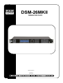
1
DSM-26MKII ORDERCODE D2072 Highlite International B.V. Vestastraat 2 6468 EX Kerkrade The Netherlands Congratulations! You have bought a great, innovative product from DAP Audio. The DAP Audio DSM-26MKII brings excitement to any venue. Whether you want simple plug-&-play action or a sophisticated show, this product provides the effect you need. You can rely on DAP Audio, for more excellent audio products. We design and manufacture professional audio equipment for the entertainment industry. New products are being launched regularly. We work hard to keep you, our customer, satisfied. For more information: [email protected] You can get some of the best quality, best priced products on the market from DAP Audio. So next time, turn to DAP Audio for more great audio equipment. Always get the best -- with DAP Audio ! Thank you! DAP Audio DAP Audio DSM-26MKII™ Product Guide Warning ................................................................................................................................................................................. 2 Safety Instructions............................................................................................................................................................. 2 Operating Determinations ............................................................................................................................................... 4 Return Procedure ............................................................................................................................................................. 4 Claims ............................................................................................................................................................................... 4 Description of the device ..................................................................................................................................................... 5 Overview .......................................................................................................................................................................... 5 Backside ........................................................................................................................................................................... 6 Installation ............................................................................................................................................................................. 7 Set Up and Operation ........................................................................................................................................................... 7 System test ........................................................................................................................................................................ 7 Menu Overview ................................................................................................................................................................ 8 Input setup ..................................................................................................................................................................... 10 Output setup .................................................................................................................................................................. 10 Load/save menu ............................................................................................................................................................ 11 The sytem menu ............................................................................................................................................................. 12 Device ID setup ......................................................................................................................................................... 12 Lock Menu Setup ....................................................................................................................................................... 13 Power On Setup......................................................................................................................................................... 14 Backlight Setup .......................................................................................................................................................... 15 Current program........................................................................................................................................................ 15 System Information .................................................................................................................................................... 15 Digital Speaker Manager software installation .................................................................................................................. 15 Software Installation ....................................................................................................................................................... 15 Installing the CP2103 USB driver ................................................................................................................................. 16 Installing the Digital Speaker Manager software ...................................................................................................... 17 Connecting a single DSM-26MKII using the USB port .................................................................................................... 19 Connecting several DSM-26MKII’s using the RS-485 ports ............................................................................................. 19 Making a connection between your PC and DSM-26MKII ........................................................................................... 20 Software operation ............................................................................................................................................................. 21 A. The information zone ................................................................................................................................................. 21 B. The display and connection zone ............................................................................................................................. 21 C. the parameter adjustment zone ............................................................................................................................... 24 Channel selection ..................................................................................................................................................... 24 Editing labels .............................................................................................................................................................. 24 Mute button ............................................................................................................................................................... 24 Curve button ............................................................................................................................................................. 25 The link function ......................................................................................................................................................... 25 Gain ........................................................................................................................................................................... 25 EQ............................................................................................................................................................................... 25 Delay .......................................................................................................................................................................... 26 Polarity ....................................................................................................................................................................... 26 X-over ......................................................................................................................................................................... 26 Compressor/Limiter.................................................................................................................................................... 26 Noise Gate ................................................................................................................................................................. 26 Source ........................................................................................................................................................................ 27 Connection Cables ............................................................................................................................................................ 27 Maintenance ...................................................................................................................................................................... 28 Replacing a Fuse............................................................................................................................................................ 28 Troubleshooting .................................................................................................................................................................. 28 Product Specifications ........................................................................................................................................................ 29 1 Warning FOR YOUR OWN SAFETY, PLEASE READ THIS USER MANUAL CAREFULLY BEFORE YOUR INITIAL START-UP! Unpacking Instructions Immediately upon receiving this product, carefully unpack the carton and check the contents to ensure that all parts are present, and have been received in good condition. Notify the dealer immediately and retain packing material for inspection if any parts appear damaged from shipping or the carton itself shows signs of mishandling. Save the carton and all packing materials. In the event that a fixture must be returned to the factory, it is important that the fixture be returned in the original factory box and packing. Your shipment includes: • DAP DSM-26MKII • DSM-26MKII Digital Speaker Manager edit software • USB cable (140cm) • IEC cable (180cm) • User manual CAUTION! Keep this system away from rain and moisture! Safety Instructions Every person involved with the installation, operation and maintenance of this system has to: be qualified follow the instructions of this manual CAUTION! Be careful with your operations. With a dangerous voltage you can suffer a dangerous electric shock when touching the wires! Before you initial start-up, please make sure that there is no damage caused by transportation. Should there be any, consult your dealer and do not use the system. To maintain perfect condition and to ensure a safe operation, it is absolutely necessary for the user to follow the safety instructions and warning notes written in this manual. Please consider that damages caused by manual modifications to the system are not subject to warranty. This system contains no user-serviceable parts. Refer servicing to qualified technicians only. IMPORTANT: The manufacturer will not accept liability for any resulting damages caused by the nonobservance of this manual or any unauthorized modification to the system. Never let the power-cord come into contact with other cables! Handle the power-cord and all connections with the mains with particular caution! Never remove warning or informative labels from the unit. Never use anything to cover the ground contact. Do not insert objects into air vents. Do not connect this system to a dimmerpack. 2 Do not switch the system on and off in short intervals, as this would reduce the system’s life. Only use system indoor, avoid contact with water or other liquids. Avoid flames and do not put close to flammable liquids or gases. Always disconnect power from the mains, when system is not used. Only handle the power-cord by the plug. Never pull out the plug by tugging the power-cord. Make sure you don’t use the wrong kind of cables or defective cables. Make sure that the signals into the mixer are balanced, otherwise hum could be created. Make sure you use DI boxes to balance unbalanced signals; All incoming signals should be clear. Make sure that the available voltage is not higher than stated on the rear panel. Make sure that the power-cord is never crimped or damaged. Check the system and the powercord from time to time. Before switching on or off make certain the sound system’s amplifiers are off or turned down: this will avoid signal peaks, which are annoying and sometimes dangerous (particularly for speaker enclosures). Avoid installing your equipment very near radio or TV sets, mobile phones, etc., as these can cause RF (radio frequency) interference. When connecting the other parts of your sound system, watch out for the so-called “ground loops”. The best way (even if not always feasible) to avoid ground loops is to connect the electric ground of all the equipment to a single central point (“star” system). In this case, the central point can be the mixer. To avoid or solve hum and buzzing troubles, try different combinations of lifting grounds on units that are supplied with ground lift switches or make sure all chassis are connected to earth ground, either through the A.C. power cord ground or by the front panel rack mount screws. Before changing your grounds around, always switch your amplifiers off. Keep this user’s manual for future consultation. Also remember that the device will get a better price on the secondhand market if (as well as being in good condition) it has its original documentation and packaging. Always operate the unit with the AC ground wire connected to the electrical system ground. Do not drive the inputs with a signal level bigger, than required to drive the equipment to full output. Please turn off the power switch, when changing the power cord or signal cable. Sometimes, when you want to send one signal to more than one amplifier, you should use a signal distributor. Extreme frequency boosts in connection with a high input signal level may lead to overdriving your equipment. Should this occur, it is necessary to reduce the input signal level by using the INPUT control. To emphasize a frequency range, you don’t necessarily have to move its respective sliding control upward; try lowering surrounding frequency ranges instead. This way, you avoid causing the next piece of equipment in your sound path to overdrive. You also preserve valuable dynamic reserve (“headroom”) For replacement use fuses of same type and rating only. Prevent distortion! Make sure that all components connected to the DSM-26MKII have sufficient power ratings. Otherwise distortion will be generated because the components are operated at their limits. Avoid ground loops! Always be sure to connect the power amps and the mixing console to the same electrical circuit to ensure the same phase! If system is dropped or struck, disconnect mains power supply immediately. Have a qualified engineer inspect for safety before operating. If the system has been exposed to drastic temperature fluctuation (e.g. after transportation), do not switch it on immediately. The arising condensation water might damage your system. Leave the system switched off until it has reached room temperature. Repairs, servicing and electric connection must be carried out by a qualified technician. WARRANTY: Till one year after date of purchase. 3 Operating Determinations This system is not designed for permanent operation. Consistent operation breaks will ensure that the system will serve you for a long time without defects. If this system is operated in any other way, than the one described in this manual, the product may suffer damages and the warranty becomes void. Any other operation may lead to dangers like short-circuit, burns, electric shock, etc. You endanger your own safety and the safety of others! Improper installation can cause serious damage to people and property ! Connection with the mains Connect the device to the mains with the power-plug. Always pay attention, that the right color cable is connected to the right place. International EU Cable UK Cable US Cable Pin L BROWN RED YELLOW/COPPER FASE N BLUE BLACK SILVER NUL YELLOW/GREEN GREEN GREEN EARTH Make sure that the device is always connected properly to the earth! Return Procedure Returned merchandise must be sent prepaid and in the original packing, call tags will not be issued. Package must be clearly labeled with a Return Authorization Number (RMA number). Products returned without an RMA number will be refused. Highlite will not accept the returned goods or any responsibility. Call Highlite 0031-455667723 or mail [email protected] and request an RMA prior to shipping the fixture. Be prepared to provide the model number, serial number and a brief description of the cause for the return. Be sure to properly pack fixture, any shipping damage resulting from inadequate packaging is the customer’s responsibility. Highlite reserves the right to use its own discretion to repair or replace product(s). As a suggestion, proper UPS packing or double-boxing is always a safe method to use. Note: If you are given an RMA number, please include the following information on a piece of paper inside the box: 1) Your name 2) Your address 3) Your phone number 4) A brief description of the symptoms Claims The client has the obligation to check the delivered goods immediately upon delivery for any shortcomings and/or visible defects, or perform this check after our announcement that the goods are at their disposal. Damage incurred in shipping is the responsibility of the shipper; therefore the damage must be reported to the carrier upon receipt of merchandise. It is the customer's responsibility to notify and submit claims with the shipper in the event that a fixture is damaged due to shipping. Transportation damage has to be reported to us within one day after receipt of the delivery. Any return shipment has to be made post-paid at all times. Return shipments must be accompanied with a letter defining the reason for return shipment. Non-prepaid return shipments will be refused, unless otherwise agreed in writing. Complaints against us must be made known in writing or by fax within 10 working days after receipt of the invoice. After this period complaints will not be handled anymore. Complaints will only then be considered if the client has so far complied with all parts of the agreement, regardless of the agreement of which the obligation is resulting. 4 Description of the device Features The DAP DSM-26MKII is professional 2 in- and 6 output speaker manager that can be used for a wide range of applications. • DAP speaker presets available at www.dap-audio.info • Powerful chipset • 96 Khz Sample rate, 115 dB dynamic range • 30 User presets • S/NR better than 110dB dBu • USB at front with included user-friendly remote software • Connect multiple units with RS485 (use optional interface D2071) • Suitable for professional PA systems, line arrays, audio installations and sound distribution systems Overview 1) Input LED indicator + mute switch The VU-meter indicates the input level. Make sure the Clip led only lights up occasionally. Pushing the mute/ edit button shortly will mute the corresponding input. Pushing and holding the mute/ edit button allows you to enter edit mode for the corresponding channel. In edit mode you are able to adjust the gain, polarity, noisegate, delay and EQ for each input separately by pushing the GAIN(11), POLARITY/NG(6), DELAY(2) or EQ(3) button. 2) DELAY button Pushing the delay button allows you to enter the delay menu directly. The delay for each input and output can be adjusted separately. 3) EQ button Pushing the EQ button allows you to enter the EQ menu directly. You can setup up to 6 different EQ’s for each input and each output. 4) X-OVER button Pushing the X-over button allows you to enter the X-over menu directly. Pushing the X-over button again let’s you select and adjust a high- and low- pass filter for each output. 5) LIMITER button Pushing the Limiter button allows you to enter the Limiter menu directly. You can set up a limiter for each output. 6) POLARITY/NG button Pushing the polarity/ng button allows you to enter the polarity/noisegate menu directly. You can adjust the polarity for each in- and output channel separately. The noisegate can be setup for the input channels only. 7) 8) Output LED indicator + mute switch The VU-meter indicates the output level. Make sure the Clip led does only light up occasionally. The limit led will light if the internal limiter is actually limiting the signal. Pushing the output mute/edit button shortly will mute the corresponding input. Pushing and holding the output mute/edit button allows you to enter edit mode. In edit mode you are able to adjust the gain, polarity, delay, EQ and crossover for each output channel separately by pushing the GAIN(11), POLARITY/NG(6), DELAY(2), EQ(3) or X-over(4) button. LCD display To display functions and operating status. 5 9) Jogwheel Dialing the jogwheel allows you to change parameters. Clicking the jogwheel allows you to enter, select or confirm. 10) EXIT button Pushing the exit button allows you to exit the current menu. 11) GAIN button Pushing the gain button allows you to enter the gain menu directly. The gain can be setup for each channel separately. 12) SYSTEM button Pushing the system button gives you access to the system setup menu. 13) LOAD/SAVE button Pushing the load/save button allows you to enter program mode menu. The program mode allows you to load/save/copy programs. 14) USB port Connecting your computer to this port allows you to edit and manage your presets, using the included DSM-26MKII Speaker Management software. Backside 15) IEC Connector + Fuse This connector is meant for the connection of the supplied main cord. Connect one end of the power cord to the connector, the other end to the mains, then turn on the power switch to operate the unit. Note: Please make sure that the supply voltage matches the operation voltage before connecting the unit to mains. Replace the fuse only with a fuse of same specification (F0,5A). 16) Power switch Do not supply power before the whole system is set up and connected properly. Make sure the 115/230V(17) switch is set to the proper voltage. 17) 115V/230V Switch Before plugging in the power cord, make sure the 115/230V switch is set to the proper voltage. 18) Ground Ground screw in case a separate ground wire is needed. 19) Ground lift switch In a properly designed system (for safety and to minimize noise), the device should receive its ground from the line cord. Whenever possible, the signal source equipment should share the same AC ground as the amplifier(s). In some cases, this may result in a ground loop. If this happens, use the ground lift switch to lift the signal ground and isolate it completely from the chassis/AC ground. 20) RS485 ports RS485 com port for linking a DSM-26MKII with your computer in case you need very long cables (up to 1500m). You can link up to 250 sets. A suitable USB to RS485 interface is the optional DAP D2071 USB to RS485 interface. 21) Output Sockets XLR male balanced output. 22) XLR Input Sockets XLR female balanced input. 6 Installation Remove all packing materials from the DSM-26MKII. Check that all foam and plastic padding is removed. Screw the equipment into a 19" rack. Connect all cables. Always disconnect from electric mains power supply before cleaning or servicing. Damages caused by non-observance are not subject to warranty. Set Up and Operation Before plugging the unit in, always make sure that the power supply matches the product specification voltage. Do not attempt to operate a 120V specification product on 240V power, or vice versa. Check the 115/230V(17) switch on the back off the device. Install this device on a flat surface, not bend or curved. Do not supply power before all components of the system are set up and connected properly. Make sure to power-up before your power amplifier is turned in order to avoid loud transients, which could damage your speakers or annoy your audience. System test After connecting all cables, you should carry out a system test. Push all Mute-buttons in order to mute all outputs. Activate the HF-outputs first. In case of wrong cabling, High Frequency (HF) signals will come out of bass-speakers that cannot be harmed this way. Vice versa, the Low Frequency (LF) signals would destroy your HF-speakers. 7 Menu Overview 8 9 Input setup 1. Push and hold the Ch A input mute/edit button(1) for 3 seconds to enter edit mode for input channel A. While in edit mode, the edit LED in the corresponding VU meter will light up orange. 2. Push the GAIN(11) button to enter the gain menu. Adjust the gain by dialling the jogwheel(9). 3. Tap the EQ(3) button to select EQ1-EQ6. Click the jogwheel(9) to select the parameter you wish to edit. Adjust the parameter by dialing the jogwheel(9). Each EQ can be switched off by selecting the frequency parameter and dialing the jogwheel(9) counterclockwise until the frequency passes 19,7Hz. 4. Push the DELAY(2) button to enter the delay menu. Adjust the delay time by dialing the jogwheel(9). 5. Push the POLARITY/NG(6) button to enter the polarity/noisegate menu. Now you are able to adjust the polarity and noise gate threshold for the corresponding input channel. Select the parameter you wish to edit by clicking the jogwheel(9). Adjust the parameter by dialling the jogwheel(9). 6. Repeat step 1-5 for input channel B. Output setup 1. Push and hold the output CH 1 input mute/edit button(7) for 3 seconds to enter edit mode for output channel 1. While in edit mode, the edit LED in the corresponding VU meter will light up orange. 2. Tap the EQ(3) button to select EQ1-EQ6. Click the jogwheel(9) to select the parameter you wish to edit. Adjust the parameter by dialing the jogwheel(9). Each EQ can be switched off by selecting the frequency parameter and dialing the jogwheel(9) counterclockwise until the frequency passes 19,7Hz. 10 3. Push the X-OVER(4) button to enter the X-over menu. Tap the X-OVER(4) button to select either a Low Pass Filter (LPF) or a High Pass Filter (HPF). Click the jogwheel(9) to select a parameter for editing and dial the jogwheel(9) to edit the parameter. 4. Push the LIMITER(5) button to enter the limiter menu. Click the jogwheel(9) to select a parameter for editing and dial the jogwheel(9) to edit the parameter. 5. Push the DELAY(2) button to enter the delay menu. Adjust the delay time by dialing the jogwheel(9). 6. Push the GAIN(11) button to enter the gain menu. Adjust the gain by dialling the jogwheel(9). 7. Push the POLARITY/NG(6) button to enter the polarity menu. Now you are able to adjust the polarity for the corresponding input channel. Select the parameter you wish to edit by clicking the jogwheel(9). Adjust the parameter by dialling the jogwheel(9). 8. Repeat step 1-7 for input channel 2-6. Load/save menu 1. Push the load/save(13) button to enter the load save menu. 2. If you want to load a (previously stored) program from memory or copy settings from one channel to another channel, Select “1. Load program” by dialing the jogwheel(9) and confirm by clicking the jogwheel(9). If you wish to store a program into memory or wish to restore the default settings, select “2. Save Program”and continue with step 6. 3. If you wish to load a program from memory, select “”group Load” by dialing the jogwheel(9) and confirm by clicking the jogwheel(9). If you wish to copy the settings from one channel to another channel, select “Channels Copy” and continue with step 5. 4. Select preset 1-30 by dialing the jogwheel(9). Click the jogwheel(9) to load the selected program. The display will indicate the progress and after successfully loading the program, the DSM-26MKII will return to play-mode. If you wish to proceed with other load or save actions return to step 1. 5. Dial the jogwheel(9) to select the channel you wish to copy the settings from. Click the jogwheel(9) and select the channel you wish to copy your settings to by dialing. Push and hold the jogwheel(9) for 3 seconds to start copying. The display will ask you to continue. Select yes and click the jogwheel(9) to start copying. Repeat this step for all the channel settings you wish to copy. Push the EXIT(10) button to exit the current menu. If you wish to proceed with other load or save actions, return to step 1 otherwise return to the start up menu. 6. If you wish to load your current active program in memory preset 1-30, select “store” by dialing and clicking the jogwheel(9). If you wish to restore a memory preset to its default setting, select “default” and continue with step 9. 7. Select the memory preset in which you want to store your program by dialing and clicking the jogwheel(9). 11 8. Use the jogwheel(9) to enter a name for your new preset. Dial to edit a character and click to select the next character. Push and hold the jogwheel(9) for 3 seconds, to store the preset. The DSM-26MKII will return to play mode. 9. To restore a preset to its default settings make sure, “default” is selected and click the jogwheel(9). The display will ask you to continue. If you’re sure, select yes by dialing and clicking the jogwheel(9). The DSM-26MKII will return to step 8, allowing you to restore more presets to its default settings. If you’re finished, tap the EXIT(10) button to return to the start up menu. The system menu The system setup menu gives you access to six sub menus as described in the following 6 paragraphs. Select a submenu by dialing the jogwheel(9). Enter the submenu by clicking the jogwheel(9) Device ID setup When using the DSM-26MKII with the supplied Digital Speaker Manager software. You need to set up the device ID. For more info, see page 20. 1. Pushing the system(12) button allows you to enter the system setup. Dial the jogwheel(9) to select 1. Device ID setup. Enter by clicking the jogwheel(9). 2. Set the device ID by dialing the jogwheel(9) and enter by clicking the jogwheel(9). 12 Lock Menu Setup The lock menu allows you to block parameters for accidental changes. You are able to block each parameter for each input and output channel separately. It is even possible to protect them with a password if necessary. 1. If you want to protect your locked parameters with a password, select “1. Create Password” and click the jogwheel(9) to confirm. Else select “No password” and proceed with step 3. 2. Dial the jogwheel(9) to edit a character, confirm and move to the next character by clicking the jogwheel(9). Your password has to consist of exactly 6 characters. When you are finished, click the jogwheel(9) and your password will be saved. 3. Use the jogwheel(9) to select “input set” and enter the input set menu by clicking the jogwheel(9). 4. Use the jogwheel(9) to select the parameter you wish to lock. The input set menu allows you to lock: Noisegate, Gain, Delay, Polarity, EQ, Mute, Ch_name, Link and All lock. Select the functions you wish to block by dialing and clicking the jogwheel(9) (on = locked). 5. Use the jogwheel(9) to select “output set” and enter the output set menu by clicking the jogwheel(9). 6. Use the jogwheel(9) to select the parameter you wish to lock. The output set menu allows you to lock: Gain, Delay, Polarity, X_over, Limite, Source, Ch_name, EQ, Mute, Ch_name, Link and All lock. Select the functions you wish to block by dialing and clicking the jogwheel(9) (on = locked). 7. Use the jogwheel(9) to select “system lock set” and enter the output set menu by clicking the jogwheel(9). 8. Use the jogwheel(9) to select the parameter you wish to lock. The system lock set menu allows you to lock Load data, Save data, Erase data, Device ID, Backlight, Key edit, Copy data, Power on and All lock. Select the functions you wish to block by dialing and clicking the jogwheel(9) (on = locked). 9. When you’re finished, push the EXIT(10) button. Now you’re in the function set menu. You can only access the function set menu if you have stored a password. If you’ve selected “no Password”, you can’t access the function set menu. 10. The function set menu is your last chance to make changes to your password setup before storing. 13 Dial and click the jogwheel(9) to select “change password” if you want to change the password you previously set up and continue with step 11. Select “erase password” if you decide to block the parameters without a password and continue with step 12. Select “Change lock Menu” if you wish to block or unblock parameters and return to step 3. 11. Dial and click the jogwheel(9) to open the change password menu and return to step 2. 12. Dial and click the jogwheel(9) to open the erase password menu. Click the jogwheel(9) to erase your previously setup password. 13. The DSM-26MKII will return to the system setup menu. Return to the start up menu by tapping the EXIT(10) button. Power On Setup Dialing the jogwheel(9) allows you to select the status of the mute button per channel when the power is switched on. You can choose between. 1. Keep state Select “Keep state” if you want to all inputs and outputs switched on or off, the way they are programmed. Confirm by clicking the jogwheel(9). 2. All mute All mute” will mute all inputs and outputs when changing a program. This to prevent your speakers and audience from annoying or even dangerous sudden signal bursts. Confirm by clicking the jogwheel(9). 3. Load Select “load” if you want to power up with preset 1. 14 Backlight Setup Dialing the jogwheel(9) allows you to select: 1. Open Select “Open” if want to keep the backlight always on. Confirm by clicking the jogwheel(9). 2. 10s Select “10s” if you want the backlight to be switched off if no key is pushed for at least 10 seconds. Confirm by clicking the jogwheel(9). Current program Shows the current program name. System Information Shows the current software version. Digital Speaker Manager software installation Software Installation If the CD doesn’t start automatically, open the CD and double click the setup.exe icon. Now the setup window as shown in the figure below will pop up. 15 Installing the CP2103 USB driver Make sure the DSM-26MKII is not connected to your computer while installing the USB driver. Click “USB Driver Installation”. The window shown in the figure below will pop up. Select the correct driver which for your operation system. The window shown below will pop up asking you to confirm your selection. Confirm if ok. Now the InstallShield wizard will guide you through the driver installation. Click the next button. Click the Finish button to complete the installation. 16 Click the back button to return to the setup window. Installing the Digital Speaker Manager software Click “Application Installation” The Digital Speaker Management setup window will pop up. Click next. If you agree with the default destination folder, click the next button. 17 Click next to proceed Click the Finish button. Now you’re ready with the installation of the Digital Speaker Management software. Exit the setup window. 18 Connecting a single DSM-26MKII using the USB port Use the supplied USB cable to connect your DSM-26MKII with your PC. The drawback of this connection is that you can only use relatively short cables. Connecting several DSM-26MKII’s using the RS-485 ports When using several DSM-26MKII in a permanent installation, we suggest connecting them to a RS485 bus. This way you can convenient create, edit and manage your patches by means of a PC. You can connect up to 250 units in parallel with standard network cables by means of the RS485 terminals at the back panel. Connect the RS485-USB interface with the DSM-26MKII’s as shown in the figure below using network cables. Turn on the power of each DSM-26MKII and change each unit’s ID-number. Push the system(10) key to enter the DSM-26MKII’s system setup. Click the jogwheel(9) to enter “Device ID Setup” Click the jogwheel(9) to enter Device ID Setup Dial the jogwheel(9) to change the ID number. Make sure, each DSM-26MKII has its own unique IDnumber. Note: You’ll need the optional D2071 USB/RS-485 converter if you want to control a DSM-26MKII by a RS485 bus. 19 Making a connection between your PC and DSM-26MKII Connect your DSM-26MKII to your PC using the included USB cable or via the optional USB/RS485 converter in combination with a network cable. Start up the Digital Speaker Management software. Click the connection button. The connection window will pop up. Check if the settings are correct and push enter. If you’re not sure which com port number is used by your by your PC, check your device manager under windows. (Properties/Hardware/ports (COM&LPT). Look for the “Prolific USB-to-Serial Comm Port”. 20 Software operation The Digital Speaker Management window can be divided into 3 zones: A. The information zone B. The display and connections zone C. The parameter adjustment zone A. The information zone The information zone displays the software version number. B. The display and connection zone 1. Program name This field shows the name of the program in the upper row and the number of the preset in the bottom row. The first time you run the Digital Speaker Management software, the “Name” row will be blank and the “NO.” row will show “default”. And the Digital Speaker Management software will be set to default settings. After the first setup, the Digital Management Software will load the settings of the program which is in the DSM-26MKII’s working memory while connecting. The display will show “working”. 21 After storing and naming a program, the name of the program will be shown in the upper row and the number of the program will be shown in the bottom row. 2. Connection display The connection button can be used to setup or change a connection. For more information, see page 16/17. The box under the connection button shows the progress of the connection setup. The device number of the connected DSM-26MKII is shown in the box under “Device Id”. 3. 4. Display Displays the curves of the input and output channels. It is also possible to edit curves by clicking and drawing the curve. Function buttons Help Click to open the help function. Program Clicking the program button opens the program window as shown below. Device program Is for the for data exchange between the DSM-26MKII and the Digital Speaker Management software. Recall program from device Allows you to recall the program currently in the DSM-26MKII’s working memory and display the settings in the Digital Speaker Management software. Store program to device Allows you to store the program currently in the Digital Speaker Management software’s working memory into the DSM-26MKII’s working memory. Store all program to device Allows you to store all programs currently in the Digital Speaker Management software’s memory into the DSM-26MKII’s memory. Recall all programs from device Allows you to recall all the programs currently in the DSM-26MKII’s memory and put the settings in the Digital Speaker Management software’s memory. Delete Clicking the delete button will delete the program selected in this window. 22 PC program Is for exchanging programs between Digital Speaker Management and your hard disk or other storage media. Recall program from PC Allows you to recall a program from your PC’s hard disk and load it in the Digital Speaker Management software. Store program to PC Allows you to store the program currently in the Digital Speaker Management software’s working memory on your PC’s hard disk. Store all program to PC Allows you to store all programs in the Digital Speaker Management software’s memory on your PC’s hard disk. Device Clicking the device button opens the window shown below. Change Current Device ID Allows you to change the ID number of the DSM-26MKII you’re currently connected to. Re-Connect to Device Allows you disconnect from the DSM-26MKII you’re currently connected with. Interface Clicking the button opens a window which allows you change the message on the display of the DSM-26MKII while the unit is standby. Interface 1 Allows you to edit the first line of the display. Interface 2 Allows you to edit the second line of the display. Notebook The notebook button opens a notepad which allows you to ad notes to a program. Report The report window allows you to view the settings of your program and to print them out or export them as an excel file. 23 C. the parameter adjustment zone Channel selection Click the channel button (INA, INB, INC, IND, OUT1, OUT2, OUT3, OUT4, OUT5, OUT6, OUT7 or OUT8) to select and edit a channel. The button will turn red, indicating the channel is in edit mode. Now you can edit the parameters to your liking. Changing a parameter will also change the corresponding curve. It is even possible to click and drag the corresponding curve in the display in order to change the parameters. Input channels: Gain, Noise gate, EQ1 – EQ6, delay and polarity. Output channels: Gain, delay, polarity, X-over, Limiter and EQ1-EQ6. Editing labels The Digital Speaker Management software allows you to ad labels to each in and output channel. If the channel is in edit mode, you can enter a name in the box above the channel button as shown in the picture below. Mute button Clicking the mute button allows you to mute the corresponding channel. 24 Curve button Clicking the curve button allows you to display the corresponding EQ curve in the display(3). The link function The Digital Speaker Management software allows you link input channels to your needs. In the example below the B input is linked with the A input. Now input B is linked with input A, all settings (except mute) from input A will automatically be copied to input B. Gain Allows you to adjust the overall gain of the selected input or output channel. Adjust the gain by typing the value in the box, by clicking the increase/ decrease buttons in the value box or by clicking and dragging the fader. Clicking the All Volume button opens a field which holds a separate fader for each channel. EQ The EQ automatically switches off if the gain is set to zero. The input channels only have parametric EQ’s. The output channels allow you to configure each EQ as parametric, low shelving or high shelving. Adjust the gain by typing the value in the box, by clicking the increase/ decrease buttons in the value box or by clicking and dragging the fader. The other parameters can be adjusted by clicking the increase/decrease buttons in the value box or by typing the new value in the box. 25 Clicking the EQ/Bypass button allows you to bypass the complete EQ section. Delay The parameters can be adjusted by clicking the increase/decrease buttons in the value box or by typing the new value in the box. Polarity Click the polarity button to inverse the polarity of that channel X-over Each output channel has its own crossover. You can select the filter type, select the slope and adjust the center frequency of both the high and low pass filter. Compressor/Limiter Each DSM-26MKII output channel has its own limiter. You can adjust the threshold, attack time and release time by clicking the increase/ decrease buttons in the value box, or by typing the new value in the box. Noise Gate Each DSM-26MKII input channel has its own noise gate. You can adjust the threshold level by clicking the increase/ decrease buttons in the value box, or by typing the new value in the box. Typing “off” in the box will bypass the noise gate. 26 Source The source window indicates which source(s) is(are) connected to the selected output channel. Clicking the checkbox allows you to change, add or delete sources. Connection Cables Take care of your cables, always holding them by the connectors and avoiding knots and twists when coiling them: This gives the advantage of increasing their life and reliability. Periodically check your cables. A great number of problems (faulty contacts, ground hum, discharges, etc.) are caused entirely by using unsuitable or faulty cables. Headphones Unbalanced mono Balanced mono 27 Insert Compensation of interference with balanced connections Maintenance The DSM-26MKII crossover requires almost no maintenance. However, you should keep the unit clean. Disconnect the mains power supply, and then wipe the cover with a damp cloth. Do not immerse in liquid. Keep connections clean. Disconnect electric power, and then wipe the audio connections with a damp cloth. Make sure connections are thoroughly dry before linking equipment or supplying electric power. Replacing a Fuse Power surges, short-circuit or inappropriate electrical power supply may cause a fuse to burn out. If the fuse burns out, the product will not function. If this happens, follow the directions below to do so. 1. Unplug the unit from electric power source. 2. Insert a flat-head screwdriver into a slot in the fuse cover. Gently pry up the fuse cover. The fuse will come out. 3. Remove the broken fuse. If brown or unclear, it is burned out. 4. Insert the replacement fuse into the holder where the old fuse was. Reinsert the fuse cover. Be sure to use a fuse of the same type and specification. See the product specification label for details. Troubleshooting Dap Audio DSM-26MKII This troubleshooting guide is meant to help solve simple problems. If a problem occurs, carry out the steps below in sequence until a solution is found. Once the unit operates properly, do not carry out following steps. 1. If the device does not operate properly, unplug the device. 2. Check the power from the wall, all cables etc. 3. If all of the above appears to be O.K., plug the unit in again. 4. If you are unable to determine the cause of the problem, do not open the DSM-26MKII, as this may damage the unit and the warranty will become void. 5. Return the DSM-26MKII to your Dap Audio dealer. 28 Product Specifications Model: DAP Audio DSM-26MKII Input gain: -80dB - +12dB, step @ 0,1 dB Input selection: Each input channel can be connected to each output channel 6-Bands Input EQ: Bandwidth: EQ gain control: EQ frequencies: 0,05 to 3 octaves in 0,05 octave steps. -20 dB to +20 dB 19,7Hz to 20kHz in 1/24 octave steps delay: Input delay: Output delay: Channel independent from 0 to 1000 mS Channel independent from 0 to 1000 mS polarity: Input polarity: Output polarity: In phase (+) or reversed phase (-) In phase (+) or reversed phase (-) Output gain: -80dB - +12dB, step @ 0,1 dB 6-Bands Output EQ: Type: Lo/High shelf slope: EQ Bandwidth: EQ gain control: EQ frequencies: Low Shelf, High Shelf and Parametric 6 dB/12 dB 0,05 to 3 octaves in 0,05 steps. -20 dB to +20 dB on al EQ types. 19,7 Hz to 20 kHz in 1/24 octave steps Crossovers: Types: Slopes: frequencies: Linkwitz Riley, Bessel and Butterworth 12, 18, 24, 30, 36, 42, 48 dB/octave 19,7 Hz to 20 kHz in 1/24 octave steps Limiter: Threshold points: Attack times: Attack time steps: Release times: -40 to +20 dBu in 0,5 dB steps 0,3 mS to 200 mS 0,1 mS steps from 0,3 to 1 mS 1 mS steps from 1 to 100 mS 50 ms – 5000 ms Miscellaneous: DSP: AD/DA Converters: Input Impedance: Output Impedance: CMRR: Input range: Frequency response: S/NR: THD: Crosstalk: Memory Storage: Mute: Display: Latency: USB Interface: RS-485 interface: Power Supply: Power Consumption: Fuse: Power Switch: Dimensions (W x H x D): Net weight: 96 kHz, 32 bits floating point DSP, 192 kHz, 24 bits A/D and D/A converters. Balanced 20kΩ Balanced 100Ω >70dB@1kHz ≤ ±25 dBu 20Hz – 20kHz ±0,5dB >110dB <0,01% @output=0dBu/1kHz >80dB@1kHz 30 User presets All channels have their dedicated mute switches 2x 24 dot matrix characters 2,61 mS 1x Front 2x Back 110/220 Volt AC, 50/60 Hz 25 Watt F0,5A/250V Back 482 x 44 x 192 mm 3,4 kg Design and product specifications are subject to change without prior notice. Website: www.Dap-audio.info Email: [email protected] 29 2013 Dap Audio.