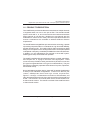
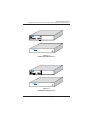
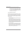
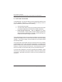
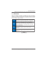
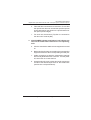
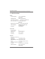
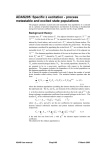
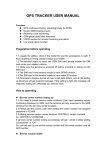
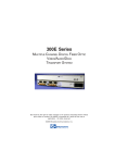
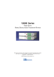
1
6100E Series
DIGITAL FIBER OPTIC MULTI-CHANNEL
AUDIO TRANSPORT SYSTEM
WITH DATA OPTIONS
BCI reserves the right to make changes to the products described herein without
prior notice or consent. No liability is assumed as a result of their use or
application. All rights reserved.
©2005 Broadata Communications, Inc.
BCI 6100E User’s Manual
Digital Fiber Optic Multi-Channel Audio Transport System with Data Options
SAFETY INSTRUCTIONS AND
COMPLIANCE DECLARATIONS
PLEASE OBSERVE THE FOLLOWING SAFETY
PRECAUTIONS AS OUR PRODUCTS CONTAIN
CLASS I LASER PRODUCTS
WARNING
Do not disconnect the fiber optic connector while the unit is powered
up. Exposure to laser radiation is possible when the laser fiber optic
connector is disconnected while the unit is powered up.
Although the fiber optic connectors in this product emit only Class 1
energy that is below the levels considered to be hazardous, one should
never stare directly into a fiber optic connector or an unconnected fiber
end unless one can be certain that no exposure to laser energy could
occur.
CAUTION
This manual is intended for use by trained service personnel. The use
of controls, making adjustments, or performing operations other than
those specified may result in hazardous radiation exposure.
The following label or equivalent is located on the surface of laser products.
This label indicates that the product is classified as a CLASS 1 LASER
PRODUCT.
CLASS 1 LASER PRODUCT
SURGE PROTECTION DEVICE RECOMMENDED
This product contains sensitive electrical components that may be
damaged by electrical spikes, surges, electric shock, lightning strikes,
etc. Use of surge protection systems is highly recommended in order
to protect and extend the life of your equipment.
Broadata Technical Support, [email protected]
3
BCI 6100E User’s Manual
Digital Fiber Optic Multi-Channel Audio Transport System with Data Options
TABLE OF CONTENTS
1.0 PRODUCT DESCRIPTION .............................................5
2.0 SETUP .............................................................................. 8
2.1 MOUNTING ......................................................................8
2.2 CABLING AND CONNECTORS ..................................... 9
2.2.1 AUDIO CABLE CONNECTION ....................................9
2.2.2 OPTICAL FIBER CONNECTION ............................... 12
2.3 AC POWER CONNECTION .......................................... 14
3.0 OPERATION ................................................................... 15
4.0 MAINTENANCE AND TROUBLESHOOTING.............. 16
4.1 MAINTENANCE ............................................................. 16
4.2 TROUBLESHOOTING .................................................. 16
5.0 SPECIFICATIONS .......................................................... 18
6.0 SERVICE PROCEDURE ............................................... 20
6.1 REPLACEMENT POLICY ............................................. 20
6.2 RETURN AND REPAIR SERVICE ................................. 20
7.0 LIMITED WARRANTY .................................................... 21
4
Broadata Technical Support, (800) 214-0222
BCI 6100E User’s Manual
Digital Fiber Optic Multi-Channel Audio Transport System with Data Options
1.0 PRODUCT DESCRIPTION
The 6100E Series provides simultaneous transmission of multiple channels
of digitized audio over one or one pair of fiber. The standard 6100E
system comes with 4-, 8-, and 16-channel versions and transmits these
audio channels in one direction. Models up to 32-channels are also
available as a custom version. Many versions of optical transmitter and
receiver combinations are available to address different distance
requirements.
The 6100E features a digital fiber optic transmission technology, capable
of providing crisp audio, little or no maintenance, high functional reliability,
and low operating costs. The quality of BCI's audio transmission digital
design is much superior to the analog transmission counterparts (based
on amplitude or frequency modulation) available from other manufacturers.
In addition, no user adjustments are required in the 6100E system,
enabling quick setup and trouble-free operation.
The 6100E is available with two packaging options: a rugged, standalone,
and compact unit, or a plug-in card for a card cage system. Panel
connectors are provided for audio (terminal block) and fiber connection
(FC-type for singlemode fiber or ST-type for multimode fiber). They are
also easily monitored by separate LED indicators for power, optical link,
and channel activity.
Due to its digital transmission design, the 6100E is capable of addressing
a variety of non-standard configurations. Contact us to discuss your
custom, OEM/private brand and high volume requirements.
Figures 1-1 through 1-4 illustrate the connections, LED indicators, and
other elements displayed in the front and rear panels of the 6108E and
6116E. The 6116E is a 16-channel audio version and the 6108E is our
8-channel audio version. The 6104E is a subset of the 6108E and is the
4-channel audio version.
Broadata Technical Support, [email protected]
5
RX
9
10
11
12
TX
1
2
3
4
PWR
11
12
9
3
10
4
15
16
13
7
14
8
13
14
15
16
A U D I O
5
6
7
8
1
6100E-T
2
+ --
+ --
5
I N P U T S
+ --
+ --
CHANNELS
BCI 6100E User’s Manual
Digital Fiber Optic Multi-Channel Audio Transport System with Data Options
6
12VDC
11
12
9
3
10
4
TX
1
2
3
4
PWR
LINK
15
16
13
7
14
8
13
14
15
16
9
10
11
12
RX
A U D I O
5
6
7
8
2
1
6100E-R
+ --
6
5
+ -- O U T P U T S + --
CHANNELS
Figure 1-1
6116E-T Front/Rear Panels
+ --
12VDC
Figure 1-2
6116E-R Front/Rear Panels
6
Broadata Technical Support, (800) 214-0222
BCI 6100E User’s Manual
Digital Fiber Optic Multi-Channel Audio Transport System with Data Options
6100E
TX
RX
A U D I O
3
TX
8
7
5
6
7
8
1
PWR
I N P U T S
4
1
2
3
4
+ --
+ --
2
CHANNELS
5
+ --
+ --
6
12VDC
Figure 1-3
6108E-T Front/Rear Panels
6100E
RX
RX
A U D I O
1
2
3
4
PWR
LINK
O U T P U T S
4
3
TX
7
8
5
6
7
8
1
+ --
+ --
2
CHANNELS
5
+ --
+ --
6
12VDC
Figure 1-4
6108E-R Front/Rear Panels
Broadata Technical Support, [email protected]
7
BCI 6100E User’s Manual
Digital Fiber Optic Multi-Channel Audio Transport System with Data Options
2.0 SETUP
The BCI 6100E Series units are used in pairs. One 6100E-T transmitter
unit is located at the near end and connected to an identical 6100E-R
receiver (6108E or 6116E, respectively) located at the far end of the link
through two optical fibers. Each unit provides a separate electrical
interface connector for the audio data signals. Connections are one to
one between both units. Figure 2-1 depicts a typical installation.
Figure 2-1
6100E Series Setup
2.1 Mounting
Before installing the units into your housing, make sure there is
enough space to pull and connect both the electrical and optical
cables without stressing them beyond the manufacturer’s
limitations (also known as the bend radius minimum). Rack
Mount kits are available through special order.
8
Broadata Technical Support, (800) 214-0222
BCI 6100E User’s Manual
Digital Fiber Optic Multi-Channel Audio Transport System with Data Options
2.2 Cabling and Connectors
In order to setup the BCI 6100E properly, make sure to observe
the following instructions when installing the proper cables. The
6100E requires two parts to the cabling setup: the audio and
the optical.
2.2.1 Audio Cable Connection
The only cable connections on the electrical side are for
the terminal block audio interfaces.
To connect the audio component, connect your terminal
block connectors to the appropriate channels, as illustrated
in Figure 2-2. The pinout assignment for the terminial block
connector is shown in Figure 2-3.
One Level
Audio Receiver
15
13
14
15
16
12
11
9
10
11
12
RX
9
3
1
2
3
4
TX
PW
R
10
4
2
+
1
+
--
--
U
A
I
N
D
P
I
14
8
13
7
O
U
6
+
5
6
7
8
5
T
S
NELS
CHAN
16
6100E-T
Unit
+
--
--
Audio Cable with
Terminal Block
Connector
T
E00
61
One Fiber
Cable
Audio Cable with
Terminal Block
Connector
To 6100E-R Unit
Figure 2-2
Audio Connection
Broadata Technical Support, [email protected]
9
BCI 6100E User’s Manual
Digital Fiber Optic Multi-Channel Audio Transport System with Data Options
6100E
TX
RX
A U D I O
3
TX
I N P U T S
4
8
7
1
2
3
4
5
6
7
8
1
PWR
+ --
+ --
Ch 1
Ch 2
Ch 3
Ch 4
2
CHANNELS
5
+ --
+ --
6
Ch 5
Ch 6
Ch 7
Ch 8
7
8
+ _ G + _
+ _ G + _
3
4
_
+
G + _
+ _ G + _
J1
J2
Figure 2-3
Terminal Block Pinout Assignment
6100E
TX
RX
A U D I O
3
TX
I N P U T S
4
8
7
5
6
7
8
1
2
3
4
PWR
6
5
2
1
1
+ --
Pin 1
CH 3(+)
Pin 3
CH 3(-)
Pin 2
CH 1(+)
Pin 4
CH 1(-)
+ --
2
CHANNELS
GND
Pin 5
CH 3&4
Pin 6
CH 1&2
GND
5
+ --
+ --
6
Pin 7
CH 4(+)
Pin 9
CH 4(-)
Pin 8
CH 2(+)
Pin 10
CH 2(-)
Table 1
6100E-T/6100E-R Terminal Block (J1) Pinout
10
Broadata Technical Support, (800) 214-0222
BCI 6100E User’s Manual
Digital Fiber Optic Multi-Channel Audio Transport System with Data Options
6100E
TX
RX
A U D I O
3
TX
7
4
1
2
3
4
PWR
I N P U T S
8
5
6
7
8
1
+ --
+ --
2
CHANNELS
5
+ --
Pin 1
CH 7(+)
Pin 3
CH 7(-)
Pin 2
CH 5(+)
Pin 4
CH 5(-)
+ --
6
GND
Pin 5
CH 7&8
Pin 6
CH 5&6
GND
Pin 7
CH 8(+)
Pin 9
CH 8(-)
Pin 8
CH 6(+)
Pin 10
CH 6(-)
Table 2
6100E-T/6100E-R Terminal Block (J2) Pinout
The following sections provide installation procedures for
connecting 6100E audio channel interfaces. Please refer to
Figure 2-2.
The audio interface in the 6108E/6116E system supports
transmission of eight/sixteen channels of high fidelity audio,
respectively. Line-level audio signals are connected to the
6100E units over balanced terminal block cable. Use the
following steps for transmission of high-fidelity audio:
1. Connect and label 8 or 16 terminal block cables to the
output connectors of the 8 or 16 line-level audio sources
to be sent.
2. Connect the terminal block cables of the 8 or 16 signals
to be transmitted to the corresponding 6100E-T rear
panel terminal block female receptacles labeled
channels 1, 2, …, 8/16.
3. Repeat Steps 1 and 2 for the receiver end (6100E-R).
Broadata Technical Support, [email protected]
11
BCI 6100E User’s Manual
Digital Fiber Optic Multi-Channel Audio Transport System with Data Options
4. Connect the terminal block cables of the 8 or 16 signals
to be received to the corresponding 6100E-R rear panel
terminal block male receptacles labeled channels
1, 2, …, 8/16. Connect and label these 8 or 16 terminal
block cables to the input connectors of the 8 or 16
line-level audio receivers/amplifier.
2.2.2 Optical Fiber Connection
Most cable manufacturers identify individual fibers in the fiber
cable. Select an appropriate terminated fiber. Each unit’s optical
ports in the system are specified for use with Multimode
(62.5/125 micron) fiber, or Singlemode (9/125 micron) fiber.
Follow the ensuing instructions for installing and connecting
the fiber optic links:
1. Ensure the power is off before proceeding with the fiber
optic cable installation.
2. Prior to connecting the fiber optic cables, remove and save
the dust caps from the optical port of both the 6100E units.
Wipe the inside of the sleeve with a lint-free pipe cleaner
moistened with regent-grade isopropyl alcohol. Clean the
fiber optic connector and use a lint-free cloth dampened
with alcohol to thoroughly wipe the side and end of the
ferrule. Table 3 shows the connection mechanisms for both
ST and FC connectors.
3. Connect the fibers from one unit to the other connecting
the near end 6100E unit’s optical TX port to the far end
6100E unit’s optical RX port as illustrated in Figure 2-4.
Observe the type of connector you have and connect the
optical connector by following the instructions and
guidelines from the legend provided below.
12
Broadata Technical Support, (800) 214-0222
BCI 6100E User’s Manual
Digital Fiber Optic Multi-Channel Audio Transport System with Data Options
11
9
10
11
12
10
4
9
3
RX
1
2
3
4
A
2
+
1
-T
TX
R
PW
13
14
15
16
12
--
U
D
I N
P
I O
14
8
13
7
5
6
7
8
U
6
+
5
T
+
--
--
S
6100E-R
Unit
--
+
E
00
RX
9
10
11
12
61
TX
PWR
One Fiber
1
2
3
4
11
12
9
3
10
4
LINK
6100E-R1
+ --
2
13
14
15
16
A U D
I O
5
6
7
8
15
16
13
7
+ -- O
5
U T P
U T S +
--
14
8
+ --
CHANNELS
6100E-T
Unit
LS
CHANNE
16
15
6
Figure 2-4
Fiber Optic Connection
C onnector
Illustration
*
Hold the connector by the strai n-reli ef boot* and i nsert
the connector ferrule i nto the port. Rotate the boot unti l
the "key" engages i n the slot of the coupli ng. Push the
c o nne c t o r ho us i ng f o r w a r d unt i l i t c a n b e t ur ne d
clockwi se to latch to the port.
*
Hold the connector by the strai n-reli ef boot* and i nsert
the connector ferrule i nto the port. Rotate the boot unti l
the "key" engages i n the slot of the coupli ng. Push the
connector housi ng forward and screw clockwi se unti l i t
i s ti ght.
ST
FC
*
SC
D escription
Hold the connector by the connector casi ng* and i nsert
the connector i nto the port. Make sure the key, si gni fi ed
by the notch on one si de of the connector ali gns wi th
the connector on the fi ber opti c equi pment.
Table 3
Fiber Optic Connector Legend
Broadata Technical Support, [email protected]
13
BCI 6100E User’s Manual
Digital Fiber Optic Multi-Channel Audio Transport System with Data Options
2.3 AC Power Connection
Congratulations! You are now ready to power up the BCI 6100E and set
up your network connection. In order to make sure that you have a
proper installation, please observe the following:
1. Your AC jack has power.
2. Your electrical system has proper grounding (this ensures that
your power supply does not suffer from voltage variations).
3. Power Surge Protection. This is optional, but highly
recommended. A UPS system provides voltage regularity as
well as prevents spikes from occurring, thus protecting your
6100E from sensitive voltage conditions.
The 6100E derives power from an external 12VDC/1.6A power supply
(6104E and 6108E) or from an internal 95-240 VAC/1.6A power supply
(6116E). This power supply comes standard for the 6100E unless
otherwise specified.
To provide power to the 6100E, simply connect the power cord, already
provided with the units, and connect it to the wall jack. (You will find one
power cord per unit). Once the power cord has been connected to the
wall jack, connect the other end to the unit. Once the power cord has
been connected, turn the switch ON (I) on the provided back panel.
If you have any problems or concerns, regarding the installation, make
sure that you have taken the proper steps to ensure a proper power
connection. Otherwise, feel free to contact us for any questions you
may have.
14
Broadata Technical Support, (800) 214-0222
BCI 6100E User’s Manual
Digital Fiber Optic Multi-Channel Audio Transport System with Data Options
3.0 OPERATION
After the installation procedure is completed, the units are ready for
operation. To operate the 6100E units, simply apply power as indicated
in the previous step. Note that the front panel link status indicator,
shown in Table 4, will be activated.
P o w er
This RED LED indicates that the 6100E-T or 6100E-R unit is
connected to a power source and the unit is switched on.
Optical
Link
The ON state of this GREEN LED on the 6100E-R unit
indicates that the fiber optic cable is properly connected and
that optical transmission is operating between the 6100E-T
and the 6100E-R units.
Audio
Out
This GREEN LED FLASHES ON when the 6100E-R
transmits audio signals to the user's audio receiver
equipment.
Audio
In
This GREEN LED FLASHES ON when the 6100E-T
receives audio signals from the user's audio source
equipment.
Table 4
Status Indicators
Broadata Technical Support, [email protected]
15
BCI 6100E User’s Manual
Digital Fiber Optic Multi-Channel Audio Transport System with Data Options
4.0 MAINTENANCE AND TROUBLESHOOTING
4.1 Maintenance
There is no operator maintenance other then keeping the units
clean. However, observe the light indicators (shown in Table 4)
to make sure that the unit is working properly.
4.2 Troubleshooting
If the BCI 6100E units do not operate properly after installation,
check for possible cable breaks, loose connections, and
incorrect cable connections. If a problem exists on the fiber
link, please check your fiber connectors for improperly cleaned
fiber cables and connectors. If problems persist that may be
fiber related, contact BCI at 1-800-214-0222 for further
assistance.
For electrical problems, perform the following troubleshooting
procedures:
1. If the POWER indicator is OFF, check for the following:
a. The line cord is plugged into the unit and your outlet
has power.
b. The 6100E unit is switched on.
c. Check for blown fuses (located in the rear panel-entry
module).
2. If the POWER indicator is ON, but the Optical Link
indicator is OFF, check for the following:
a. Make sure the appropriate (singlemode or multimode)
fibers are being used.
16
Broadata Technical Support, (800) 214-0222
BCI 6100E User’s Manual
Digital Fiber Optic Multi-Channel Audio Transport System with Data Options
b. Fiber and fiber connectors are not broken. Ensure that
the optical loss does not exceed the specified optical
power attenuation (see Section 5.0 Specifications for
the optical power budget).
c. For each unit, the transmit (TX) fiber is connected to
the other unit’s receiver (RX).
3. If the POWER indicator and Optical Link indicator are
ON, but the audio/video channels are not operating,
then:
a. Check to see that the attached user equipment is turned
on.
b. Both ends of the link are connected to the corresponding
equipment and to the same corresponding channel port.
c. Cable connections at both the video/audio channels
are securely fastened to each connector. Turn the power
off, then back on to reset the link.
d. Output levels of the user’s video and audio sources are
not above the allowed input levels of the 6100E units
(see Section 5.0 Specifications).
Broadata Technical Support, [email protected]
17
BCI 6100E User’s Manual
Digital Fiber Optic Multi-Channel Audio Transport System with Data Options
5.0 SPECIFICATIONS
Audio
Channel Capacity
4, 8, or 16 (Standard)
32 (Custom)
Operating Mode
Balanced/Unbalanced
Input/Output Impedance
600/600 Ohms (Balanced)
Max. Input/Output Level+10dBm @ 600 Ohms
(Balanced)
Magnitude Freq. Response 20Hz to 20kHz @ -3dB
SNR (Weighted)
80dB @ 1kHz, 0dBm Input
Level (Balanced)
Connector
Terminal Block
Serial Data
Channel Number
8
Signal Format
RS-232 or RS-422
Data Rate
Up to 115 Kb/s
Connector
Terminal Block
Physical
Dimension: (H x W x D)
Standalone*
1.72'' x 8.58'' x 12.0''
Standalone**
1.72'' x 17.03'' x 12.0''
Card-cage Plug-in Card 5.24” x 0.94” x 11.6”
Power
+12 VDC @ 1.6 A (4 or 8-ch)
Operating Temperature 0 to +50oC
Humidity
0 to 95% RH, non-condensing
Status Indicators
Power, Optical Link,
Audio Activity
18
Broadata Technical Support, (800) 214-0222
BCI 6100E User’s Manual
Digital Fiber Optic Multi-Channel Audio Transport System with Data Options
* For 4- or 8-channel, and for 16-channel unidirectional
** For 16-channel bi-directional
Optical
Fiber Type
Multimode and Singlemode
Number of Fibers
1
Wavelength
1310 and/or 1550 nm
Fiber Optic Connector ST (Multimode)
FC (Singlemode)
Broadata Technical Support, [email protected]
19
BCI 6100E User’s Manual
Digital Fiber Optic Multi-Channel Audio Transport System with Data Options
6.0 SERVICE PROCEDURE
6.1 Replacement Policy
Standard products found defective on arrival (DOA) will be
replaced, based on availability, within 24 to 48 hours anywhere
in the U.S. Please call Customer Service at 800-214-0222 for
information.
6.2 Return/Repair Service
The 6100E System contains no user serviceable components.
If you have a problem with your unit, please contact the
Customer Service Department. To facilitate our return/repair
processing please contact Broadata Communications, Inc. to
obtain a Return Material Authorization (RMA). Please include
the following information:
•
•
•
•
Product model number
Serial Number
Complete description of problem
Hardware installation description
Broadata Communications, Inc.
2545 West 237th Street, Suite K
Torrance, CA 90505
1-800-214-0222
(310) 530-1416
(310) 530-5958 (Facsimile)
e-mail: [email protected]
Website: www.broadatacom.com
20
Broadata Technical Support, (800) 214-0222
BCI 6100E User’s Manual
Digital Fiber Optic Multi-Channel Audio Transport System with Data Options
7.0 LIMITED WARRANTY
Broadata Communications, Inc. (BCI) warrants, for a period of one year
from date of shipment, each product sold shall be free from defects in
material and workmanship. BCI will correct, either by repair, or at BCI’s
election, by replacement, any said products that in our sole discretion
prove to be defective and are returned to the manufacturing location
within 30 days after such defect is ascertained. All warranties are limited
to defects arising under normal use and do not include malfunctions or
failure resulting from misuse, abuse, neglect, alterations, electrical power
problems, usage not in accordance with product instructions, improper
installation, or damage determined by BCI to have been caused by the
Buyer or repair made by a third party. Limited warranties granted on
products are to the initial customer end-user and are not transferable.
OUR LIABILITY UNDER THIS WARRANTY SHALL IN ANY CASE BE
LIMITED TO THE INVOICE VALUE OF THE PRODUCT SOLD AND BCI
SHALL NOT BE LIABLE TO ANYONE FOR CONSEQUENTIAL OR
INCIDENTAL DAMAGES ARISING FROM THE USE OF ITS PRODUCTS
OR THE SALE THEREOF. We make NO WARRANTY AS TO THE
MERCHANTABILITY OF ANY GOODS, OR THAT THEY ARE FIT FOR
ANY PARTICULAR PURPOSE OR END APPLICATION NOR DO WE
MAKE ANY WARRANTY, EXPRESSED OR IMPLIED OTHER THAN
AS STATED ABOVE.
Broadata Technical Support, [email protected]
21
BCI 6100E User’s Manual
Digital Fiber Optic Multi-Channel Audio Transport System with Data Options
22
Broadata Technical Support, (800) 214-0222
Broadata Communications, Inc.
2545 West 237th Street, Suite K
Torrance, CA 90505
1-800-214-0222
(310) 530-1416
(310) 530-5958 (Facsimile)
e-mail: [email protected]
Website: www.broadatacom.com
6000E-6100-C1