1
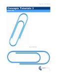
Contents User Manual Laser Distance Sensor OWLF series 1. 2. 3. 4. 5. 6. 7. 8. 9. 10. 11. 12. 13. 14. Safety instructions Introduction Functional principle Mounting instructions Application hints Teaching the OWLF Alarm output Synchronization input Technical data Connection diagram and pin assignment Grounding concept Service notes Accessories Troubleshooting 3 4 5 6 11 15 32 33 37 40 41 42 43 44 Welotec GmbH Zum Hagenbach 7 D-48366 Laer www.welotec.com [email protected] Fon: +49 (0)2554/9130-00 Fax: +49 (0)2554/9130-10 Seite / Page 2 1 Safety instruction 2 Laser safety • The laser diode installed in the OWLF emits visible red laser lights. This laser belongs to the Class 2 laser standard specified by the IEC 60825-1 / 2001. It also complies with 21 CFR 1040.10 and 1040.11 except for deviation pursuant to laser notice No. 50, July 2001. • Max. average output power < 1 mW • Laser radiation, do not stare into beam • To avoid uncontrolled laser exposure we recommended stopping the beam with a matte object. • For laser safety reasons, the voltage supply of the sensors must be turned off when the whole system or the machine is turned off. • Safety concept information and limiting parameters as published in the sales documentation apply at all times. Introduction The latest generation of laser distance sensors are setting new standards in terms of speed and performance. The short response time (300…900µs) makes it possible to measure small and fast moving objects up to 600 mm away and 0.3...2.7ms up to 1000 mm away. The advanced teach-in function allows arbitrarily configuring the measuring range between the default limits in order to increase the resolution. This allows the complete output swing of 4 – 20 mA and 0 – 10 V to be mapped on the new range. The alarm output switches on as soon as the sensor receives no usable signal or as soon as the object is outside the measuring range. The sync. output allows the sensor to synchronize the measurement or to use several sensors in a non-synchronous mode when they would normally interfere optically or to synchronize sensors to a machine clock or pulse. The distance measurement is based on the triangulation principal. The use of a photodiode array as the receiver and the intelligence of a high performance microcontroller produce measuring results that are almost independent of object colors and just a very small linearity error in the analog output signal. The rugged sensor has a metal housing with a front cover made of glass. The 90° rotating connecter allows wiring the sensor from the bottom or the rear . Seite / Page 3 Seite / Page 4 3 Functional principle 4 The distance measured is based on the triangulation principle. The emitted laser beam falls on the object as a small light spot and will be reflected diffusely. The position of the received light spot on the receiver (a diode line) defines the receiving angle. This angle corresponds to the distance and is the base for the internal calculations. A distance change close to the sensor effects a large change in angle; the same distance change at the end of the measuring range has a much smaller effect to the angle. This non-linearity feature is linearized by the microcontroller. The analog output signal is linear to the distance. Mounting instructions • For a proper mounting, the mounting surface has to be flat. Be aware of the max. tightening torque. • In case of EMC, the sensor has to be grounded and a shielded cable has to be used. • The 90° rotating connecter allows wiring the sensor from the bottom side or from the rear. • The max. accuracy will be reached >15 minutes after power on. Steps / edges: Diode line with receiving light spot Object close to sensor Object far away The sensor adapts automatically to different object colors by varying the emitting laser intensity and optimizing the exposure time. The result is a sensor that is nearly independent on different reflections (different colors, shiny surfaces, dark objects). The sensor reaches its highest accuracy if the object reflects diffusely. When measuring right next to steps / edges, it is important that the receiving beam is not covered by the steps / edges. This also applies to depth measurements of holes or valleys. Seite / Page 5 Seite / Page 6 Mounting above shiny surfaces: On shiny surfaces, it is important that no direct reflection can get to the receiving optics. The reflection could blind the sensor and produce poor results. To prevent this, the sensor may be slightly tilted. The direct reflection can be seen on a white piece of paper when held in front of the receiver. Objects with color edges in the same direction: When color edges are orientated in the right direction, the effect to the measuring result will be minor. If the color edges are in the wrong direction, the effect will depend on the reflectivity of the different colors. Shiny objects with a constant structure Especially shiny objects with a constant structure (lathed or scuffed objects, extruded aluminum profiles, etc.) could have a negative effect on the measuring result. Mounting above round, shiny surfaces: Seite / Page 7 Seite / Page 8 Profile measurement: For profile measurements, the sensor axes should be perpendicular to the moving direction. Several sensors without mutual optical interferences: Several sensors, when mounted next to the other, can affect each other. When mounting a sensor, be aware that no laser spot from another sensor is in the receiving field. When mounted side by side (as shown in the picture in the middle), sensing distances up to 600 mm can be achieved.. Measuring range Measuring range Ambient light: Be careful that no strong light source faces the receiving field. Measuring range mutual optical interferences If it is not possible to mount the sensors the correct way, use the sync input and choose the asynchronous function. Seite / Page 9 5 Seite / Page 10 Application hints To reach the maximum accuracy of OWLFxxx series laser distance sensors, keep an eye on the following points: Measuring on rough surfaces All laser distance sensors are adjusted and linearized on a reference object. The object is a white ceramic sheet with an absolutely flat surface. Many objects have a surface structure that is within the resolution of the sensor or rougher. In such a case, the sensor with its small laser spot measures the distance including the structure in contrast to a slide gauge that measures an average. For such applications, we recommend to use a laser distance sensor with a laser line (OWLF 4xxx S1 L). Flat surface distance max. min. Rough surface OWLF What can you do if you have color edges? For a high accuracy measurement, it is necessary that the laser spot reflects constantly and diffusely. Frequently, the object surface has different colors (black-white transition) or parts with different reflectivity (marble plate). If the laser spot falls just on a changing contrast (color edge), half of the spot will be reflected well and the other part not so well. This produces a signal on the receiver that can not be analyzed perfectly and causes a measuring fault. Whole spot reflected with the same reflectivity accurate measurement Spot on a color edge measuring fault Slide gauge ! Seite / Page 11 Seite / Page 12 Often objects have several color edges on the surface. What can you do if you have transparent, semi-transparent and highly reflective objects? for example: The measuring principle desires an object that reflects the light diffusely. Semi-transparent, transparent and highly reflective objects do not have this feature. text ! pictures ! grooves ! rust ! ! marble Measure with Laser Sensors • • • In the field, you have no guarantee that the spot is not falling on just a color edge that can cause a measuring fault. Also, when the object moves, you may get an incorrect signal for each color edge (it appears that the signal is unstable or has spikes) In such cases, we suggest to move the object (or sensor), take several measurment values and calculate the average. The quantity of measurment values depends on the structure, the moving speed and the accuracy you desire. Other possible solutions: use a sensor with the laser line (OWLFxxxxS1 L) contact Welotec When measuring on semi-transparent objects, the light enters the object and so the measured distance is larger than the actual distance is. Light will pass through a transparent object so a measuring signal is not available. A highly reflective object only has a direct reflection and it is not possible to work with it. For such an application, ask Welotec. to measure these objects, it is only possible if you place a diffuse reflecting surface on the object (sticker, etc.) ! Semi transparent objects: the light enters the object. the measured distance is larger than the real distance Teaching the OWLF Every sensor is delivered with the factory setup (max. measuring range). The teach-in feature was designed to choose a smaller range within the nominal measuring range for optimizing the resolution and linearity. Output current, voltage and alarm output adapt to the new range. Two positions must be taught. • The first teach-in position aligns with 0 V (or 4 mA), the second position aligns with 10 V (or 20 mA) • These teach-in positions are always just at the border of the new range (inside the measuring range) • The sensor may be taught more than 10,000 times in its lifetime • The sensor can always be reset to the factory settings • The sensor may be taught with the teach button or via the external teach input • During the teach-in process, the red LED and the alarm output provides a feedback • The red LED on the back side of the sensor and the alarm output indicate “run” mode if an object is within the measuring range. Attention: Within 5 minutes after power on, the sensor can be taught via the button or the teach-in wire. After 5 minutes, the teach-in button will be locked preventing accidental adjustment. The teach-in wire is active all the time. Highly reflective objects: Only direct reflection Transparent objects: The light passes the object without a diffuse reflection. No measurment is possible Example of a taught measuring range: Analog out 10V / 20 mA No measurmentis possible Example of a taught output curve Standard output curve 0V / 4mA Alarm out LED m Example of a reverse taught measuring range: Analog out 10V / 20mA m 0 3 Example of a reversed output curve m m 0 3 1 3 1 Standard output curve 0V / 4mA Alarm out LED m Seite / Page 15 Seite / Page 14 Seite / Page 13 6 m Seite / Page 16 0 3 m m 0 OWLF 4007 Fa S1 (L) Typical resolution: MR = taught measuring range OWLF 4013 FA S1 (L) Typical linearity error: MR = taught measuring range Typical resolution: MR = taught measuring range Seite / Page 17 OWLF 4030 FA S1 (L) Typical resolution: MR = taught measuring range Typical linearity error: MR = taught measuring range Seite / Page 18 OWLF 4060 FA S1 (L) Typical linearity error: MR = taught measuring range Seite / Page 19 Typical resolution: MR = taught measuring range Typical linearity error: MR = taught measuring range Seite / Page 20 OWLF 4100 FA S1 (L) Typical resolution: MR = taught measuring range OWLF 4100 FS S1 (L) Typical linearity error: MR = taught measuring range Typical resolution: Typical linearity error: MR = taught measuring range MR = taught measuring range Seite / Page 21 6.1 How to teach a new range using the teach button Seite / Page 22 Timing of the teach procedure Teaching a new measuring range: Within 5 minutes after power-up, the button may be used to teach a new range. After finishing a teach procedure, the 5 minutes starts again. After the 5 minutes, the sensor does not respond to pressing the button. Seven steps to teaching a new measuring range: 1. 2. 3. 4. 5. 6. 7. Press (and hold) the button. The red LED will turn on, if the sensor can be taught. Hold down the button for 5 more sec. The LED will start to blink. Release the button. Place a target at the first new position of the measuring range. This is the position that will later produce 0 V (or 4 mA). Briefly press the button again. The LED will stop blinking and will stay on for about 3 sec to indicate that the first position has been stored. Then the LED will blink again. Now place the target at the second position (the other end of the new range), which will produce 10 V (or 20 mA). Briefly press the button again. The LED will stop blinking and will stay on for about 3 sec to indicate that the second position has been stored. The LED will then turn off and blink once more. Now the sensor is ready to measure. t1 t2 t3 t4 t5 red LED LED is ON if the procedure was successful t6 The new, smaller operating range is now set. The red LED now indicates whether an object is within the new range (LED OFF) or not (LED ON) If one of the new borders of the range was outside the standard range or the two positions were too close to each other, then the new settings are not valid. The sensor will respond with an extended blinking at the end of the teach procedure. The previous settings are still valid and the new settings are lost. Seite / Page 23 Seite / Page 24 LED blinks if the procedure was not successful 6.2 How to reset the factory settings using the teach button 6.3 Within 5 minutes after power up, the button may be used to reset the sensor back to the factory settings. After finishing a teach procedure, the 5 minutes starts again. After the 5 minutes, the sensor does not respond to the button. 1. 2. 3. Push the button. The red LED will turn on, if the sensor can be taught. Hold down the button further 5 sec. The LED will start to blink. DO NOT RELEASE the button now. Wait another 10 sec until the LED is ON without blinking. Factory settings have been restored to the sensor. Release the button. How to teach a new range using the external teach input Teaching the sensor via the external teach input is equivalent to the teaching procedure via the button. There is no 5 min. time limit. The sensor may be taught at any time. In addition to the LED, the alarm output is used to indicate the state of the sensor for an external digital controller. 12-28 V Teach-in wire t7 t8 t9 0V t1 t2 t4 t3 red LED Until button has been released (t13) t12 (t1 t5 Alarm output red LED t10 t6 Seite / Page 25 Seite / Page 26 Delay between teach signal and response on alarm output: 6.4 How to reset the factory settings using the external teach input Teaching the sensor via the external teach input is equivalent to the teaching procedure via the button. There is no 5 min. time limit. The sensor may be taught at any time. The alarm output can be used as an acknowledge signal for a control system. external teach input t10 t11 alarm output 12-28 V t15 Teach-in wire 0V t1 red LED Input circuit: teach-in low: 0 .. 2V high: 12 .. 28V t14 27kΩ 10kΩ Alarm output 3V3 Seite / Page 27 Seite / Page 28 Delay between teach signal and response on alarm output: Time Description of timing functions Value t1 Minimum button hold time to enter teach mode 5s t2 Maximum waiting time after teaching the first position. external teach input t11 alarm output t3 t4 t5 t6 t7 LED on as response for the first position. Maximum waiting time after teaching the second position. t9 t10 t11 t12 t13 t14 t15 Pulse lengths on external teach input for first position. Pulse lengths on external teach input for second position. Delays between teach signal and response on alarm output at the rising edge of the signal. Delay between teach signal and response on alarm output at the falling edge of the signal Minimum blinking time for the reset to factory settings with button. Blinking time after reset to factory settings Minimum blinking time for the reset to factory settings with external teach input. Minimum high time of the external teach input after the alarm output has been set at the end of the setting of the factory settings. approx 3 s < 20 s LED on and “OK response” after the second position. LED Blinking for “NOT OK response” after teaching the second position. Minimal time between high/low transition of alarm output high/low transition of the external teach input at the beginning of the teach. Seite / Page 29 t8 < 20 s 7 approx 3 s approx 5 s 1 ms Alarm output The alarm output indicates when an object is outside the measuring range or when the received signal cannot be used for measuring distance. In this case, the output shows 0 V (4 mA). 30 .. 2000 ms The sensor has no internal hold function if measured values are missing. It provides real time measuring. In some critical applications (poorly reflective objects), the sensor sometimes loses the signal and the output signal drops down to 0 V (4 mA). For such applications, we recommend to use the alarm output. Before reading the analog signal, observe the alarm output; if it is active, the analog signal must be invalid. < 20 ms < 10 ms 10 s As long as the button is down or the external teach input is high. 10 s 0.2 s Seite / Page 31 If the button has not been pushed during this interval, the sensor will leave the teach mode without any changes. Seite / Page 30 30 .. 2000 ms > 0.2 s Comment Using the button, this feature can only be used within 5 minutes after power-up. Using the external teach input, it may be used at any time. If the button has not been pushed during this interval, the sensor will leave the teach mode without any changes. Seite / Page 32 8 Synchronization input Synchronizing several sensors Hold function of the analog output / switching off the laser diode If 12-28 V is being applied to the sync input, then the sensor will hold the value of the current measurement and will switch off the laser diode. It will wait until the sync input goes back to low (0 V) before it starts a new measurement. After every measuring cycle, the sensor will test the sync input again. After the high signal on the synch. Input, it takes one cycle T1 until the hold situation is reached. Several sensors may be synchronized using an external clock. The clock cycle must be low for less than T1. The total time of a cycle must be at least T2. Within 20 cycles all sensors will be synchronized. 12-28V sync. signal T1 T2 0V Sensor OWLF 4007 + 4013 + 4030 + 4060 FA S1 (L) OWLF 4100 FA S1 (L) OWLF 4100 FS S1 (L) 12-28 V synch signal T1 0V Low/high edge of sync signal Sensor OWLF 4007 + 4013 + 4030 + 4060 FA S1 (L) OWLF 4100 FA S1 (L) OWLF 4100 FS S1 (L) 12-28 V synch. input S1 Seite / Page 34 Sensor OWLF 4007 + 4013 + 4030 + 4060 FA S1 (L) OWLF 4100 FA S1 (L) OWLF 4100 FS S1 (L) t1 < 0.9 ms < 2.7 ms < 10 ms t2 0.5 ~ 2.7 ms 0.5 ~ 8.1ms 3 ~ 10 ms t1 is the max. time after a high signal on the synch. input of S1 until the analog value will be held. This value will be held as long the signal on the synch. input is high. The min. time between the high signal of S1 and the low signal of S2 is t1, also. In this case, an optical influence between the sensors is not possible. t2 is the time until the analog signal is ready after a low signal on the synch. input of S2. This time depends on the reflectivity of the object and if the reflectivity changes during the hold time. t1 20 mA analog output S1 4 mA Input circuit 12-28 V 0V T3 5 µs ~ 450 µs 15 µs ~1800 µ s 0.1 ~7 ms T1 0.9 ms 2.7 ms 10 ms Several sensors in non-synchronous use To prevent a negative mutual influence, using several OWLF, the sensor can be used with a non-synchronous trigger pulse. 12-28 V must be applied to the sync input, so that the laser will be turned off. The following timing has to be obtained (S1 = sensor 1, S2 = sensor 2). synch. input S2 T2 >1000 µs >3 ms >10.5 ms If sensors are being synchronized this way, they all start their cycles at the same time. This means they start to sample light together. The length of the sampling interval T3 or shutter time depends on the surface. It may range from T3. White or gray objects reflect well enough to enable a less than half the sampling of interval T3. Only very dark objects actually need the maximum sampling interval. Seite / Page 33 0V T1 10 ~ 250 µs 10 ~ 250 µ s 0.01 ~ 3 ms t2 20 mA analog output S2 sync in low: 0 .. 2V high: 12 .. 28V 27kΩ 4 mA 10kΩ Seite / Page 35 3V3 Seite / Page 36 9 Technical data OWLF OWLF 4007 FS S1 (L) 4013 FS S1 (L) 4030 FS S1 (L) 4060 FS S1 (L) 4100 FS S1 (L) 4100 FA S1 (L) Measuring range Min Teach-in range 1) Resolution * Linearity error *2) 3) Response time * 4) Ambient light * Typ. Temperature 5) coefficient * Light source Laser class W ave length 6) Laser spot * 7) Laser line* high width 30~70 mm ≥ 2 mm 4~20 µm ±12~±60 µm 300~900 µs < 50k Lux 30~130 mm 50~300 mm 100~600 mm 200~1000 mm 200~1000 mm ≥ 3 mm ≥ 5 mm ≥ 10 mm ≥ 20 mm ≥ 10 mm 5~60 µm 0.01~0.33 mm 0.015~0.67mm 0.12~3.0 mm 0.02~0.5 mm ±15~±200 ±0.03~±1.0 ±0.05~±2.0 ±0.48~±12.0 ±0.08~±2.0 mm mm mm mm µm 3~10ms 300~900 µs 300~900 µs 300~900 µs 300~2700 µs < 40k Lux < 8k Lux < 10k Lux < 5k Lux < 10k Lux 0.015%v.MB/°C 0.03%v.MB/°C 0.03%v.MB/°C 0.03%v.MB/°C 0.05%v.MB/°C 0.02%v.MB/°C 1 ~ 0.2 mm 2 ~ 1 mm 2 mm 1~0.2 mm 3~5 mm 2~1 mm Anal og output Load resistor UOut Load resistor IOut Alarm output Voltage supply range Suppl y current Laser diode red, pulsed 2 675 nm 2 mm 2 mm 4~12 mm 5.5~21 mm 2.5 mm 2.5 mm 4 – 20 mA and 0 – 10 V > 100 kΩ < (+Vs – 6 V) / 0.02 A PNP / max. 100 mA Reverse polarity protection Short circuit protection Housi ng material Tightening torque Protection class Tem perature range 4007 FS S1 (L) 4013 FS S1 (L) 4030 FS S1 (L) 4060 FS S1 (L)4100 FS S1 (L) 4100 FA S1 (L) yes (voltage supply only) yes Die-cast zi nc 1.0 Nm IP 67 0 ~ +50°C (non condensing) *1) and *2) measured on white ceramic sheet *3) the response time depends on the reflectivity of the object *4) max. sunlight on a white measuring surface xx% of full scale measuring range / °C *6) and *7) dimension of laser beam: OWLF 4xxx Ø diameter *5) 2 mm 2 mm 8.5~35 mm 2.5 mm 6~20 mm 2.5 mm OWLF 4xxx (L) measuring range width Seite / Page 37 Seite / Page 38 10 Connection diagram and pin assignment OWLF 4100 FA S1 (L): Connection diagram Pin assignment * emitter axis 16 mm Seite / Page 39 measuring range Ø – beam 12 – 28 VDC OWLF 4xxx FS S1 (L): size laser beam height < 120 mA, (bei + 24V ~ 40mA) Dimensions Aluminum 1.5 Nm Seite / Page 40 11 Grounding concept 12 For maximum EMC protection and reliable application, use a shielded cable. Also, the sensor has to be grounded. We recommend the grounding concept as shown in the picture. Ground the sensor with a toothed washer between the screw head and the sensor. Service notes The OWLF requires no maintenance apart from keeping the front windows clean. Dust or fingerprints can impair the sensor function. It is normally sufficient to wipe the windows dry with a clean (!), soft cloth. Alcohol or soapy water may be used for heavy soiling. • = electrical connection Power-supply A/D Converter OWLF If you prefer another grounding concept please contact Welotec. Seite / Page 41 13 Accessories Seite / Page 42 14 Connecting cable, straight ZWK D12 Gk28, length 2 m ZWK D12 Gk58, length 2 m ZWK D12 Gk108, length 2 m Mounting bracket ZWR OWLE/OWLF Front window Protective disk / protective foil laser sensor OWLE/OWLF Troubleshooting Error The sensor does not measure The sensor has incorrect measuring values The sensor does not reach the accuracy Seite / Page 43 Possible reason Correction The sync. input or the teach-in Connect sync. input or the teach-in wire is connected to +Vs wire to 0 V The receiving beam is covered Make sure that no object is in the by an object / edge / step receiving field No receiving signal (transparent Make sure that the laser spot falls on a diffuse reflecting surface or highly reflective object) Mutual optical interferences Make sure that no other light spot is between two or more sensors within the receiving field of the sensor Strong ambient light. Prevent ambient light with a shield Semi transparent, transparent or Make sure that the laser spot falls on a highly reflective objects diffuse reflecting surface Rough surface Possibly use a sensor with laser line s e g d e r o l o C y a Resolution of the A/D converter Read the manual of the control unit in the control unit Seite / Page 44 w t