1
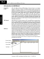
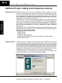
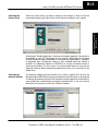
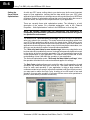
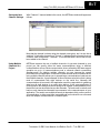
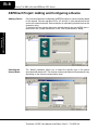
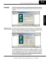
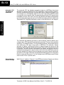
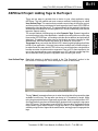
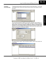
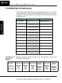
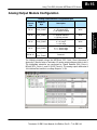
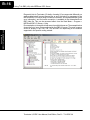
Using the T1H--EBC(100)
1B
with KEPDirect OPC Server
In This Appendix. . . .
— Introduction to KEPDirect
— KEPDirect Project: Adding and Configuring a Channel
— KEPDirect Project: Adding and Configuring a Device
— KEPDirect Project: Adding Tags to the Project
— T1H--EBC(100) I/O Addressing
— Analog Output Module Configuration
B--2
Using T1H--EBC(100) with KEPDirect OPC Server
Appendix B
EBC(100) with KEPDirect
Appendix A
Introduction to KEPDirect
Introduction
to OPC
OPC, OLE (Object Linking and Embedding) for Process Control, is an industry
standard created by a number of worldwide leading hardware and software
suppliers in cooperation with Microsoft. The OPC Data Access specification, as
maintained by the OPC Foundation, is a non--proprietary technical specification that
defines a set of standard interfaces based upon Microsoft’s OLE/COM technology.
An OPC server (driver) allows items such as distributed control systems,
programmable logic controllers, I/O systems and smart field devices to
communicate with a wide range of HMI/SCADA (client) software packages residing
on a PC. Traditionally, each software or application developer was required to write a
custom interface, or server/driver, to exchange information with hardware field
devices. OPC eliminates this requirement allowing manufacturing customers true
plug and play connectivity and the freedom to choose products based on their
automation requirements.
DDE Support
While KEPDirect is first and foremost an OPC server, KEPware recognized that a
number of legacy applications still depend upon DDE for their underlying client
server technology. Early in the development of Windows, Microsoft provided a
generic client server technology called DDE (Dynamic Data Exchange). DDE did
provide a basic architecture that would allow many windows applications from a
wide range of vendors to share data. But there was one problem, DDE was not
designed for the industrial market lacking much of the speed and robustness desired
in an industrial setting. However, this did not stop DDE from becoming a dominant
client/server architecture, largely due to its availability in most windows applications.
KEPDirect
KEPDirect Enhanced OPC/DDE Server is a 32 bit windows application that provides
a means of bringing data and information from a wide range of industrial devices and
systems into client applications on your Windows PC. KEPDirect falls under the
category of a ”Server” application. It is very common to hear the term ”client/server
application” in use across many software disciplines and business segments. In the
industrial market, it has usually come to mean the sharing of manufacturing or
production data between a variety of applications ranging from human machine
interface software and data historians, to large MES and ERP applications.
At a high level, the KEPDirect OPC Server is comprised of several objects that are
described on the next page.
Channel Object
Device Object
Group Object
Tag Object
Terminator I/O EBC User Manual, 2nd Edition, Rev B -- T1H--EBC--M
Using T1H--EBC(100) with KEPDirect OPC Server
B--3
Channel Object: Each protocol or driver used in a KEPDirect project is referred to
as a channel. A channel refers to a specific communications driver. A KEPDirect
project can consist of many channels each with unique communications drivers or
each with the same communications driver.
Each channel name must be unique in a KEPDirect application. The channel name
entered here will be part of the OPC browser information.
Group Object: KEPDirect allows tag groups to be added to your project. Tag groups
allow you to tailor the layout of OPC data in logical groupings that fit the needs of your
application. Using tag groups allows multiple sets of identical tags to be added under
the same device. This can be very convenient when a single device handles a
number of similar machine segments. From an OPC client standpoint, the use of tag
grouping allows you to segregate your OPC data into smaller tag lists, which can
make finding a specific tag easier when browsing the server.
Tag Object: KEPDirect allows both dynamic tags, (tag entered directly at the OPC
client that specify device data) and user defined tags. User defined tags have the
benefit of allowing the tag to be browsed from an OPC client that supports tag
browsing. User defined tags also support tag scaling. Unlike many of the dialogs you
will find in KEPDirect, the tag properties dialog has a number of features that are
driven by icons. The tag name is part of the OPC browse data. Tag names must be
unique within a given device branch or tag group branch. If your application is best
suited by using blocks of tags with the same names, use tag groups to segregate the
tags.
Terminator I/O EBC User Manual, 2nd Edition, Rev B -- T1H--EBC--M
Appendix B
EBC(100 with KEPDirect
Device Object: Unlike the channel name, ”Device names” can be the same from
one channel to the next. The device name is a user defined logical name for the
device. The device name and channel name will be part of the OPC browser
information as well as a DDE item name. Within an OPC client the combination of
channel name and device name would appear ”ChannelName.DeviceName”.
B--4
Using T1H--EBC(100) with KEPDirect OPC Server
Appendix B
EBC(100) with KEPDirect
Appendix A
KEPDirect Project: Adding and Configuring a Channel
Running the Server KEPDirect, like any OPC server, can be started a number of ways. One of the
benefits of OPC technology is that your OPC client can automatically invoke the
server when it attempts to connect and collect data from it. In order for this automatic
mode of operation to occur you must first create and configure a project. Once you
have created a project, KEPDirect will automatically select the most recently used
project when it is invoked by an OPC client.
Initially however, you need to manually invoke KEPDirect using either the desktop
icon, if you chose to install it, or by selecting KEPDirect from the windows start menu.
Depending on any changes you may have made to the appearance of KEPDirect,
once invoked you should be presented with the following interface. To learn more
about the various elements of the user interface see (Basic KEPDirect
Components).
While discussing how to start KEPDirect its important to understand what the system
requirements are for running the server. KEPDirect has been designed to place as
little strain on your system as possible.
Recommended System Requirements:
400Mhz Pentium
64 Megs of Ram
10 Megs of Hard Disk Space
Windows NT(SP6a)/2000 (Strongly recommended for industrial settings)
Available Ethernet Card
Adding a Channel
A channel refers to a specific communications driver. A KEPDirect project can
consist of many channels each with unique communications drivers or each with the
same communications driver. Depending on the driver or drivers you have installed
you can define a number of channels within a single project. A channel acts as the
basic building block of an OPC link. Properties like communications port, baud rate,
and parity are contained at the channel level. Each channel name must be unique in
a KEPDirect project. The channel name can be up to 31 characters long.
To add a new channel to your project you can use the Edit menu > New Channel, the
Toolbar Add Channel, or the “Click to add a channel” dialog.
Terminator I/O EBC User Manual, 2nd Edition, Rev B -- T1H--EBC--M
Using T1H--EBC(100) with KEPDirect OPC Server
Selecting the
Device Driver
B--5
Select the device driver you want to assign to the channel. A driver list will be
presented displaying all of the device drivers that are installed in your system.
Appendix B
EBC(100 with KEPDirect
Selecting the ”Enable diagnostics” check box will enable diagnostic information to
be available to your OPC application for this channel. With diagnostic functions
enabled, diagnostic tags are available for use within client applications. In addition
to diagnostic tags, a diagnostic window is also available when this feature is
enabled. The diagnostic features of KEPDirect do require a minimal amount of
overhead processing. For this reason it is recommended that you only use the
diagnostic features when needed and disable them when not in use which is the
default case.
Selecting the
Network Adapter
The Network Interface selection allows you to select a specific NIC card for the
Automationdirect EBC Ethernet driver to use based on the NIC name or its assigned
IP address. By selecting a specific NIC interface you will be able to force the driver to
send all Ethernet communication through the specified NIC. If you do not know
which NIC you should use, select the ”Default” condition.
Terminator I/O EBC User Manual, 2nd Edition, Rev B -- T1H--EBC--M
Appendix B
EBC(100) with KEPDirect
Appendix A
B--6
Using T1H--EBC(100) with KEPDirect OPC Server
Setting the
Server Writes
Optimizations
As with any OPC server, writing data to your device may be the most important
aspect of your application. Insuring that the data written from your OPC client
application gets to the device in a timely manners is the goal of the server. KEPDirect
provides a number of optimization settings that can be used to tailor the server to
meet the needs, and improve the responsiveness of your application.
There are currently three write optimization modes. The following is a brief
description of the modes. For a detailed explanation, refer to the “Channel
Properties -- Write Optimizations” section in the KEPDirect on--line help file.
NOTE: We strongly suggest that you characterize your application for
compatibility with these write optimization enhancements before using them
in a production environment.
The default mode, ”Write all values for all tags” will force the server to attempt to
write every value to the controller. This mode insures that everything written from
your OPC client applications will be sent to the target device. While writing every
value to the device may seem like the best course of action, there are a number of
applications where writing every value, many of which may be the same value, over
and over may be simply a waste of communications bandwidth.
The ”Write only latest value for non--boolean tags” allows any value that is not a
boolean value to be updated in the server’s internal write queue and will then be sent
to the device at the next possible opportunity. This can dramatically improve the
overall performance of your application. This feature must be used with a clear
understanding of how it will affect the operation of your application.
The final write optimization mode, ”Write only the latest value for all tags”, takes
the operation described for the second mode and applies it to all tags.
The Duty Cycle selection allows you to control the ratio of write operations to read
operations. By default the duty cycle is set to ten. This means that ten writes will
occur for each read operation. If your application is doing a large number of
continuous writes but you need to insure that read data is still given time to process,
you may want to reduce the Duty Cycle. A setting of one will result in one read
operation for every write operation. In all cases if there are no write operations to
perform, reads will be processed continuously.
Terminator I/O EBC User Manual, 2nd Edition, Rev B -- T1H--EBC--M
Using T1H--EBC(100) with KEPDirect OPC Server
Saving the New
Channel Settings
B--7
With “Channel1” channel added to the server, the KEPDirect window will appear as
follows:
Using Multiple
Channels in a
Project
KEPDirect supports the use of multiple channels. As you add channels to your
project you can specify either the same communications driver or different
communications drivers. Most communication drivers offered by KEPware support
operation on up to 16 communications ports or ethernet network connections
simultaneously. By defining multiple channels you can improve the overall
performance of you application. In the case of either a serial driver or Ethernet driver
using multiple channels allows you to spread large communications loads across
the multiple channels. A good example of this would be a serial driver that is being
used to communicate with eight devices on the serial line. Normally the
communications driver used in this application would be responsible for gathering
data from all eight devices in a round robin fashion. If this same application is
reconfigured to use multiple channels assigned to multiple communications ports,
the device load can be divided across the channels. The end result is reduce work
load on each channel and dramatic improvements in the responsiveness of your
application. The need to use multiple channels is dependent solely on the needs of
your application. In either case there is no additional cost involved to use a licensed
driver on multiple communications or Ethernet ports.
Terminator I/O EBC User Manual, 2nd Edition, Rev B -- T1H--EBC--M
Appendix B
EBC(100 with KEPDirect
Note that the channel is shown using the channel name given, but it is also has a
small red ”x” below the channel icon. The red ”x” indicates that the channel does not
contain a valid configuration. “Channel1” is not valid because a device has not yet
been added to the channel.
B--8
Using T1H--EBC(100) with KEPDirect OPC Server
Adding a Device
Once a channel has been configured in a KEPDirect project, a device must be added
to the channel. Devices represent PLCs, I/O devices or other hardware that the
server will communicate with. Device selection is restricted by the device driver the
channel is using.
To add a device to a channel, select the desired channel and use the Edit menu >
New Device, the Toolbar Add Device, or the “Click to add a device” dialog.
Selecting the
Device Model
The ”Model” parameter allows you to select the specific type of the device
associated with a device ID. The contents of the model selection drop down will vary
depending on the chosen communication driver.
Appendix B
EBC(100) with KEPDirect
Appendix A
KEPDirect Project: Adding and Configuring a Device
Terminator I/O EBC User Manual, 2nd Edition, Rev B -- T1H--EBC--M
Using T1H--EBC(100) with KEPDirect OPC Server
Selecting the
Device Model
B--9
The ”Device ID” parameter allows you to specify the driver specific station or node
address for a given device. Since the Automationdirect EBC driver is an Ethernet
based driver, a unique and valid TCP/IP address must be entered. IPX protocol is not
supported.
Appendix B
EBC(100 with KEPDirect
Setting the Device Device timeout parameters allow a driver’s response to error conditions to be
Timeout Properties tailored to the needs of your application. The timeout parameters are specific to each
device you configure. Each of the field parameters is defined in detail in the “Device
Properties -- Timeout” section in the KEPDirect on--line help file.
The ”Connection timeout” allows the time required to establish a socket
connection to a remote device to be adjusted. The ”Request timeout” is used by all
drivers to determine how long the driver will wait for a response from the target
device. The ”Fail after” parameter is used to determine how many times the driver
will retry a communications request before considering the request to have failed. If
your environment is prone to noise induced communications failures you may want
to increase the number of retries the driver performs.
Terminator I/O EBC User Manual, 2nd Edition, Rev B -- T1H--EBC--M
Using T1H--EBC(100) with KEPDirect OPC Server
Automatic OPC
Tag Database
Generation
The automatic OPC tag database generation features of KEPDirect have been
designed to make the setup of your OPC application a Plug and Play operation.
Since the Automationdirect EBC communication driver supports this feature, you
can configure it to automatically build a list of OPC tags within KEPDirect that
correspond to device specific data. The automatically generated OPC tags are then
browsable from your OPC client. The OPC tags that are generated are dependent
upon the nature of the supporting driver. Each field selection is defined in detail in the
“Automated OPC Tag Base Generation” section in the KEPDirect on--line help file.
Appendix B
EBC(100) with KEPDirect
Appendix A
B--10
The ”Automatic tag database generation on device startup” selection allows you to
configure when OPC tags will be automatically generated. There are three possible
selections. The default condition, ”Do not generate on startup”, will prevent the driver
from adding any OPC tags to tag space of KEPDirect. The selection ”Always
generate on startup”, will cause the driver to always evaluate the device for tag
information and to add OPC tags to the tag space of the server each time the server
is launched. The final selection ”Generate on first startup” will cause the driver to
evaluate the target device for tag information the first time this KEPDirect project is
run and to add any OPC tags to the server tag space as needed. When the automatic
generation of OPC tags is selected, any tags that are added to the server’s tag space
must be saved with the project. You can configure your KEPDirect project to auto
save from the Tools > Options menu.
Saving the New
Device Settings
With “Device1” added to “Channel1”, the KEPDirect window will appear as follows:
Terminator I/O EBC User Manual, 2nd Edition, Rev B -- T1H--EBC--M
Using T1H--EBC(100) with KEPDirect OPC Server
B--11
KEPDirect Project: Adding Tags to the Project
User Defined Tags
Each field selection is defined in detail in the “Tag Properties” section in the
KEPDirect on--line help file. A brief description of each is listed below.
The tag ”Name” parameter allows you to enter the string that will represent the data
available from this tag. The tag name can be up to 31 characters in length. While
using long descriptive names is generally a good idea, keep in mind that some OPC
client applications may have a limited display window when browsing the tag space
of an OPC server. The tag name is part of the OPC browse data. Tag names must be
unique within a given device branch or tag group branch. If your application is best
suited by using blocks of tags with the same names, use tag groups to segregate the
tags.
Terminator I/O EBC User Manual, 2nd Edition, Rev B -- T1H--EBC--M
Appendix B
EBC(100 with KEPDirect
There are two ways to get data from a device to your client application using
KEPDirect. The first method and most common method of defining tags is called
User Defined Tags. This requires that you define a set of tags in the server project
and then use the name you assigned to each tag as the item of each OPC/DDE link
between the client and the server. The primary benefit to this method is that all user
defined tags are available for browsing within OPC clients. Additionally, user defined
tags also support scaling.
The second method of defining tags is called Dynamic Tags. Dynamic tags allow
you to define tags in the client application. Instead of providing the server with a tag
name as the OPC/DDE item, you would provide the device address (and optionally a
data type). The server will create a tag for that location and start scanning for data
automatically. KEPDirect allows tag groups to be added to your project.
Tag groups allow you to tailor the layout of OPC data in logical groupings that fit the
needs of your application. Using tag groups allows multiple sets of identical tags to
be added under the same device. This can be very convenient when a single device
handles a number of similar machine segments. From an OPC client standpoint, the
use of tag grouping allows you to segregate your OPC data into smaller tag lists,
which can make finding a specific tag easier when browsing the server.
Appendix B
EBC(100) with KEPDirect
Appendix A
B--12
Using T1H--EBC(100) with KEPDirect OPC Server
The ”Address” parameter allows you to enter the desired driver address for this tag.
To determine how an address should be entered, you can use the Hints button next
to the address parameter. Hints provide a quick reference guide to the address
format of the driver. Once you have entered an address you can test it using the
check address button. When pressed, the check address button attempts to validate
the address with the driver. If the driver accepts the address as entered no message
will be displayed. If an error is detected a pop--up will inform you of the error. Keep in
mind that some errors will be related to the data type selection and not the address
string.
The ”Description” parameter allows you to attach a comment to this tag. A string of
up to 64 characters can be entered for the description. If you are using an OPC client
that supports Data Access 2.0 Tag Properties, the description parameter will be
accessible from the Item Description property of the tag.
The ”Data Type” selection allows you to specify the format of the tag’s data as it is
found in the physical device. The data type setting is an important part of how a
communication driver reads and writes data to a device. For many drivers the data
type of a particular piece of data is rigidly fixed.
The available data type selections are:
S
Default -- This type allows the driver to choose its default data type see the
specific driver help for details
S
Boolean -- Single bit data On or Off
S
Char -- Signed 8 bit data
S
Byte -- Unsigned 8 bit data
S
Short -- Signed 16 bit data
S
Word -- Unsigned 16 bit data
S
Long -- Signed 32 bit data
S
Dword -- Unsigned 32 bit data
S
Float -- 32 bit Real value IEEE format
S
String -- Null terminated ASCII string
S
Double -- 64 bit Real value IEEE format
S
BCD -- Two byte packed BCD value range is 0 -- 9999
S
LBCD -- Four byte packed BCD value range is 0 -- 99999999
The ”Client access” selection allows you to specify whether this tag is Read Only or
Read/Write. By selecting Read Only you can prevent client applications from
changing the data contained in this tag. By selecting Read/Write you are allowing
client applications to change this tag’s value as needed.
The ”DDE scan rate” parameter allows to you specify the the update interval for this
tag when used in a DDE client. OPC clients can control the rate at which data is
scanned by using the update rate that is part of all OPC groups.
The ”Allow client to override data type” selection allows you force OPC clients to
use the data type you have specified for this tag. OPC clients can specify how they
desire to view the data from a particular tag.
Terminator I/O EBC User Manual, 2nd Edition, Rev B -- T1H--EBC--M
Using T1H--EBC(100) with KEPDirect OPC Server
Creating a
User Define Tag
B--13
To determine how an address should be entered, use the Hints button “?” to the right
of the address field. Hints provide a quick reference guide to the address format of
the driver.
The window below shows a valid configured channel, device and several user
defined tags.
Terminator I/O EBC User Manual, 2nd Edition, Rev B -- T1H--EBC--M
Appendix B
EBC(100 with KEPDirect
Once you have entered an address you can test it using the check address “n”
button. When pressed, the check address button attempts to validate the address
with the driver. If the driver accepts the address as entered no message will be
displayed. If an error is detected a pop--up will inform you of the error. Keep in mind
that some errors will be related to the data type selection and not the address string.
Below is an example of a valid tag properties.
B--14
Using T1H--EBC(100) with KEPDirect OPC Server
Appendix A
T1H--EBC(100) I/O Addressing
I/O slots must be individually addressed in the following form: S<ss>:<t><nn> where
ss is the slot number (1 to 93), t is the address type (DI, DO, WI, WO, etc.), and nn is
the address. The address ranges from 0 to an upper limit determined by the module
occupying the slot.
Appendix B
EBC(100) with KEPDirect
I/O Type
T1H--EBC(100) I/O
Addressing
Example
Terminator I/O
EBC Module
Slot 0
Serial I/O Port
EBC:SP0.item
Syntax
Data Type
Discrete Inputs
DI<nn>
nn = Bit Number (decimal)
Boolean, Byte, Char,
Word, Short, DWord, Long
Discrete Outputs
DO<nn>
nn = Bit Number (decimal)
Boolean, Byte, Char,
Word, Short, DWord, Long
Byte Inputs
BI<nn>
nn = Bit Number (decimal)
Byte, Char
Byte Outputs
BO<nn>
nn = Bit Number (decimal)
Byte, Char
Word Inputs
WI<nn>
nn = Bit Number (decimal)
Word, Short
Word Outputs
WO<nn>
nn = Bit Number (decimal)
Word, Short
DWord Inputs
DWI<nn>
nn = Bit Number (decimal)
DWord, Long
DWord Outputs
DWO<nn>
nn = Bit Number (decimal)
DWord, Long
Float Inputs
FI<nn>
nn = Bit Number (decimal)
Float
Float Outputs
FO<nn>
nn = Bit Number (decimal)
Float
Double Inputs
DBI<nn>
nn = Bit Number (decimal)
Float
Double Outputs
DBO<nn>
nn = Bit Number (decimal)
Float
Each field selection is defined in detail in the “Tag Properties” section in the
KEPDirect on--line help file.
Slot 1
Slot 2
Slot 3
8 Digital Input 16 Digital Input 8 Digit Output
Addresses
S1:DI0
to
S1:DI7
Addresses
S2:DI0
to
S2:DI15
Addresses
S3:DO0
to
S3:DO7
Slot 4
16 Digital
Output
Addresses
S4:DO0
to
S4:DO15
Slot 5
8 Analog Input
Addresses
S5:DWI0
to
S5:DWI7
Terminator I/O EBC User Manual, 2nd Edition, Rev B -- T1H--EBC--M
Slot 6
16 Analog
Output
Addresses
S6:DWO0
to
S6:DWO15
Using T1H--EBC(100) with KEPDirect OPC Server
B--15
Analog Output Module Configuration
Analog Output Module Configuration Byte
KEPDirect
Byte
Description
Bit 24
DO0_POINT
Outputs Enable
0 = All outputs OFF
1 = All outputs Enabled
Write
Bit 25
DO1_POINT
Unipolar / Bipolar
0 = Unipolar selected
1 = Bipolar selected
Write
Bit 26
DO2_POINT
5V / 10V Range
0 = 5V range
1 = 10V range
Write
Bit 27
DO3_POINT
0 -- 20mA / 4--20mA Range
0 = 0 -- 20mA range
1 = 4 -- 20mA range
Write
Bit 28--31
DO4_POINT
-DO7_POINT
Reserved
--
The following example shows the KEPDirect OPC Quick Client (discussed in
Appendix C) used to setup a Terminator I/O analog output voltage module in slot 3.
The highlighted selections are configured for Output Enabled (DO0_Point=1),
BiPolar (DO1_Point=1), and 5V (DO2_Point=0). The analog output data value is
1024 decimal and results in a voltage output of --2.5V.
Terminator I/O EBC User Manual, 2nd Edition, Rev B -- T1H--EBC--M
Appendix B
EBC(100 with KEPDirect
Module
Control
Byte
Appendix B
EBC(100) with KEPDirect
Appendix A
B--16
Using T1H--EBC(100) with KEPDirect OPC Server
Diagnostic bits for Terminator I/O family of analog I/O are supported differently on
each module but will present themselves as error bits/values or messages to the
KEPDirect EBC I/O server using a common convention. A complete definition of the
error information, and it’s format convention, is available in the AutomationDirect
EBC Help file. This can be accessed either from the Start Menu > Program >
KEPDirect EBC I/O Server > Help
Documentation or through the Help menu from within the server. The example below
shows the list of error codes supported by the EBC I/O server. The most common
errors for analog I/O are 139, 142, 155, and 200--216 depending on the features
supported in the specific analog module.
Terminator I/O EBC User Manual, 2nd Edition, Rev B -- T1H--EBC--M