1
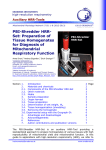
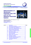
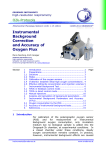
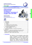
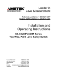
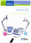
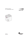
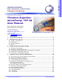
F Oxygraph-2k Manual 1.3.A. Mitochondr. Physiol. Network 12.10: 1-28 (2010) Oxygraph-2k Series B-D, DatLab 4.3 2007-2010 OROBOROS Version 4: 2010-05-24 Titration-Injection microPump. TIP-2k User Manual Mario Fasching, Lukas Gradl, Philipp Gradl, Erich Gnaiger OROBOROS INSTRUMENTS Corp. high-resolution respirometry Schöpfstr. 18, A-6020 Innsbruck, Austria T +43 512 566796 E-mail: [email protected] http://www.oroboros.at TIP-2k OROBOROS Oxygraph-2k 1. TIP-2k Main Features .................................................................................. 2 2. Setting up the TIP-2k .................................................................................. 2 2.1. 2.2. 2.3. 2.4. 3. Filling and Mounting the Syringe ................................................................. 4 3.1. 3.2. 3.3. 3.4. 3.5. 4. TIP-2k - Components.................................................................................. 2 Installation................................................................................................ 3 Manual Operation ....................................................................................... 3 Safety ...................................................................................................... 4 Filling the TIP Syringe................................................................................. 5 Mounting a Filled TIP Syringe ....................................................................... 7 Inserting the TIP Needle into the Oxygraph-2k Chamber.................................. 7 Washing the TIP Needle after Use................................................................. 8 Prevention of TIP Needle Clogging ................................................................ 9 Operation of the TIP-2k with DatLab 4 ...................................................... 10 4.1. TIP Control [F8]: Quick Start and Introduction ............................................ 10 4.2. The Control Window - Overview ................................................................. 11 4.3. The Structure of a TIP Setup...................................................................... 11 4.4. Creating and Editing TIP Setups ................................................................. 12 4.5. Setting the Parameters for a Program Line................................................... 13 The Direct Control Mode ............................................................................... 15 The Feedback Control mode.......................................................................... 16 4.6. Saving, Loading, and Managing Setups........................................................ 21 4.7. Running a TIP Setup Program .................................................................... 23 4.8. The Chemicals Window ............................................................................. 24 4.9. TIP Configuration Window ......................................................................... 24 4.10. The Info Window .................................................................................... 24 4.11. TIP Status ............................................................................................. 25 4.12. TIP Events............................................................................................. 26 [email protected] www.oroboros.at 1. 3. A. 1.3.A. Titration-Injection microPump TIP-2k 2 1. TIP-2k Main Features TIP-2k - 2-Channel Titration-Injection microPump: The TIP-2k provides unique advantages for applications which require highest accuracy of titration volumes and automatic control of complex titrationinjection protocols. The TIP-2k was specially developed for the Oxygraph2k. The main modes of operation are automatic multi-step injections, continuous injections for steady-state respirometry, (both operated form the direct control mode), and feedback controlled operation. Direct Control Mode: Operation mode for delivering a defined volume in a short pulse. A number of cycles, N, can be defined, and the duration of the interval from injection to injection determined, repeating the process N times. Several such steps can be programmed to run in sequence to give an entire TIP program. Feedback Control Mode: Operation mode to reach and maintain a certain parameter (e.g. oxygen concentration) by automatic TIP injections. 2. Setting up the TIP-2k Operation of the TIP-2k is exclusively possible in conjunction with the Oxygraph-2k and Datlab 4. 2.1. TIP-2k - Components Dimensions D x W x H: 270 x 124 x 160 mm (without syringes); stainless steel housing, 2 mm thick. Weight: 3.0 kg. TIP-2k Syringes: Simultaneous operation of two 500 µl Hamilton syringes; 0.09 mm inner diameter flexible stainless steel needles, 270 mm length. All programmed volumes and flows will be calculated erroneously if the syringe mounted does not match the specifications in the Datlab “TIP Configuration” window. Voltage supply: The power supply of the TIP-2k and electronic control is integrated into the Oxygraph-2k. OROBOROS INSTRUMENTS OROBOROS Oxygraph-2k 1.3.A. Titration-Injection microPump TIP-2k 3 2.2. Installation Placement: The TIP-2k is placed at the top of the Oxygraph-2k. It does not need any extra bench space. Align the rear ends of the TIP-2k and the Oxygraph-2k. This leaves space for a syringe cooling box which will be available as an accessory. Environment: The TIP-2k was tested at room temperature and must be protected from temperature fluctuations and condensation of water. The instrument must not be exposed to chemicals or vibrations, and the syringes should not be exposed to direct sunlight during operation. Cable: A 0.5 m cable connects the TIP-2k to the Oxygraph-2k at the rear, with a 15 pin female SubD plug. When the TIP-2k is connected to the Oxygraph-2k, and the mains of the Oxygraph-2k is switched on, the green light within the rear button on the side of the TIP-2k lights up, indicating proper connection. 2.3. Manual Operation Syringe holders (blue POM) are mounted on each side of the TIP, for a syringe with its needle guided into the left and right Oxygraph-2k chamber. The front part of the OROBOROS INSTRUMENTS OROBOROS Oxygraph-2k 1. 3. A. 1.3.A. Titration-Injection microPump TIP-2k 4 holders is static, for fixation of the glass cylinder of the syringe, while the rear part is moved with the step motor of the TIP, for fixation of the plunger. Push buttons are placed on the right side of the TIP-2k. Push the front one for forwards movement, and the rear one for backwards movement of the plunger holder. For stopping the manual movement, simply release the push button. Pushing both buttons simultaneously also stops the pump. At manual operation of the TIP-2k, the step motor moves at maximum speed. Front and rear limit: When the front or rear limit of the pump is reached, the motor stops automatically. This status is indicated by the blinking green light on the rear push button. After a short push on the TIP button in the other direction, the TIP is in the status ready, the green light is on without blinking. 2.4. Safety Potential Hazards: When not inserted into the oxygraph chamber, the needles of the TIP syringes may - due to their length and flexibility - inflict serous injuries to the eyes. Dangerous chemicals may be splashed out of the syringes by unintentionally operating the TIP. If a blocked syringe is used in the TIP, the syringe may fracture under the applied pressure and serious injury especially to the eyes may occur by glass fragments. Safety Rules: Always wear safety goggles! Never operate the TIP with a blocked syringe! When operating the TIP without the needles being inserted into the chamber: Place the end of the needle securely into a recipient vessel, to avoid any hazards to persons or instruments by jetting the solution out of the needle! 3. Filling and Mounting the Syringe Dust and any remains in the syringe cause clogging of the needle as well as wearing of the plunger. When using a blocked needle, the pump may be damaged OROBOROS INSTRUMENTS OROBOROS Oxygraph-2k 1.3.A. Titration-Injection microPump TIP-2k 5 owing to the generation of high pressure. Therefore carefully read and observe the instructions for washing the needles and prevention of needle clogging. TIP! Any inclusion of gas bubbles in the syringe must be avoided. Solutions must not be subjected to an increase in temperature during or after filling. Otherwise, gassing out will give rise to bubbles which cause erroneous titration volumes or undesirable hysteresis effects. Do not over-bend the stainless steel needles, since this causes irreversible damage. 3.1. Filling the TIP Syringe Before filling the syringe make sure that it is clean and rinsed with the solvent in which the substance to be titrated-injected is dissolved. Filling the TIP syringe can be done by back-filling after removal of the plunger, or through the needle while pulling the plunger backwards. The back-filling of the TIP syringe is faster when enough solution is available for completely filling the syringe. If injection solution is limiting, however, it is possible to fill the syringe with a small volume (e.g., 50 µl) using suction force. Back-filling the TIP syringe – requires >500 µl solution: Remove the plunger from the syringe. Fix the syringe in vertical position on a holder. Using a standard injection syringe with a long needle, fill the TIP syringe from bottom to top, without inclusion of gas bubbles at the bottom or on the glass wall. The plunger is inserted while a small amount of the solution is first extruded on the top. Once a tight fitting of the plunger is obtained, the solution is extruded through the needle. The small diameter and length of the needle cause a substantial resistance against ejection of the solution. The plunger should be inserted to the maximum volume mark of the syringe. Place the end of the needle securely into a recipient vessel, to avoid any hazards to persons or instruments by jetting the solution out of the needle. Manually Filling the TIP syringe through the needle – is possible with <<500 µl solution: 1. Push the plunger completely into the TIP syringe. 2. Immerse the tip of the needle into the titration solution and pull the plunger slowly back to the desired volume OROBOROS INSTRUMENTS OROBOROS Oxygraph-2k 1. 3. A. 1.3.A. Titration-Injection microPump TIP-2k 6 mark. It is advisable to suck in some extra volume since some solution may be spilled while attempting to remove any trapped air bubbles. 3. Allow for a slow pressure equilibration, until most of the gas space is filled by the solution. A small gas volume fills the space between the plunger and the solution. 4. Hold the syringe vertically with the needle pointed up and gently tap at the side of the syringe at the point where the air bubble is trapped. The bubble moves up the syringe to the needle outlet. Position the bubble at the centre of the glass syringe, directly at the opening to the needle, by gently tapping at the side of the syringe. 5. Slightly press the plunger to squeeze out the bubble, whereby some solution may be lost from the syringe. If the bubble moves to the side while pressing the plunger, stop pushing and gently tap the syringe tip until the bubble is located centrally, and continue. Avoid any undesired contact with the titration solution, and prevent the long needle from moving uncontrolled, which may be dangerous for the eyes. 6. After the bubble has been displaced from the glass part of the syringe, eject further about 10 - 20 µl to flush the entire needle with solution. Filling a syringe with the TIP-2k 1. Before mounting the syringe make sure that it is clean and rinsed with the solvent in which the substance to be titrated-injected is dissolved. 2. Push the plunger fully into the syringe. 3. Move the pump to the front limit. Fix the plunger heads and syringe glass cylinders of both syringes with the screws of the syringe holders. 4. Insert the tips of the needles into the titration-injection solution. 5. Shortly press the rear push button of the TIP-2k to change the status from “TIP: Front limit” to “TIP: Ready”. The green light at the centre of the TIP-2k rear button stops blinking and is on. 6. In DatLab, open the TIP Control window [F8], and select “TIP backward”. OROBOROS INSTRUMENTS OROBOROS Oxygraph-2k 1.3.A. Titration-Injection microPump TIP-2k 7 7. Set the “Volume µl” to be filled in the syringes. It is advisable to fill some more volume than required for the titration-injection experiments. Select the flow to a low value to minimize gassing out from the solution. 8. Click on Test start to fill the syringe. Provide time for pressure equilibration within the syringe. For instance, if 100 µl is filled at a flow of 50 µl/s, about 60 to 90 s are required until the pressure difference is relaxed by the slow flow of solution. 9. Remove the syringes from the syringe holders, and expel the trapped air bubble as described above. 3.2. Mounting a Filled TIP Syringe 1. Move the pump manually to or towards the rear limit. 2. Loosen the screws on the syringe holders, and insert the syringe, with the volume markings facing upward. 3. Fix the plunger head with the screw of the rear part of the syringe holder, fastening it finger tight. 4. Before fixing the front syringe holder, repeat steps 2-3 with the second syringe on the other side of the TIP. 5. Use two fingers of the left hand to hold both syringes, while pressing the front button on the TIP-2k to move the syringes forwards until the protruding edges of the glass cylinder touch the front syringe holders. Release the push button as soon as both syringes have reached this final position. 6. Fix the syringes with the screws of the front syringe holders, fastening them finger tight. Move the syringe manually forward if excess solution should be ejected. Place the end of the needle securely into a recipient vessel, to avoid any hazards to persons or instruments by jetting the solution out of the needle. 3.3. Inserting the TIP Needle into the Oxygraph-2k Chamber Before inserting the needle into the Oxygraph-2k chamber, rinse the surface carefully. In DatLab, open the TIP Control window [F8], set a low flow, and click on Test start (for details see below). No events are set when using Test start instead of Start in the F8 window. Stop the pump after a small droplet of the solution appears at the tip of the needle. Remove the extruded drop, preferentially with a plastic tip, not OROBOROS INSTRUMENTS OROBOROS Oxygraph-2k 1. 3. A. 1.3.A. Titration-Injection microPump TIP-2k 8 to withdraw any solution from the capillary. The latter might occur when using a paper towel. Place the spacer of the needle, leaving a length of 55 mm to the end. This spaces the needle end just above the stirrer in a closed 2 ml Oxygraph-2k chamber. Be careful not to touch the stirrer bar with the tip of the needle, when inserting the needle through the titanium capillary of the stopper into the chamber of the Oxygraph-2k. Alternatively (e.g. for working with a different chamber volume) adjust the position of the spacer interactively: Put the spacer in a short distance to the end of the needle, insert the needle into the stopper and push the needle further down to the desired depth, while visually controlling the position through the window. For the next usage the spacer will already be in the correct position. 3.4. Washing the TIP Needle after Use Immediately after use the following steps should be done: 1. Remove the needles from the chamber 2. Extrude some volume from the needle (e.g. by pressing the manual forward button). Place the end of the needle securely into a recipient vessel, to avoid any hazards to persons or instruments by jetting the solution out of the needle. 3. Rinse the outside of the needle with water to remove any media. This must be done before rinsing the interior of the syringe with any non-aqueous solvents! 4. Rinse the needles several times with an appropriate solvent (i.e. one in which the substances used are soluble). Usually this will be the same solvent you used during TIP operation. 5. Empty the syringe and store in a safe place. It will usually not be possible to remove all solvents from the needle. Therefore, before using the needle again, remember to rinse the needle with a pure solvent. If a needle was washed with water and an ethanolic solution of a water insoluble substance is filled into the syringe without prior rinsing with ethanol the needle will be blocked. The same will happen in the reverse case. If a TIP syringe is harder to operate than usually, start immediately with extensive cleaning procedures. Once a needle is totally blocked it is usually impossible (with OROBOROS INSTRUMENTS OROBOROS Oxygraph-2k 1.3.A. Titration-Injection microPump TIP-2k 9 exceptions) to clean it. Suitable solvents for extensive cleaning procedures depend on the substances used. Chloroform was successful for some fatty acids. An ultrasonic bath may be helpful in cleaning partially blocked syringes. 3.5. Prevention of TIP Needle Clogging Reasons for Needle Clogging: To prevent washing out effect when the needle is inserted into the chamber the inner diameter of the TIP needle has to be very small. This means that the needle is easily blocked by small particles either precipitated from the solution or introduced with the solution. While a TIP syringe has to be considered a consumable, it is possible to lengthen its lifetime by carefully following the procedures suggested in this manual. Prevention: The main way to prevent clogging of needles is to follow rigorously the cleaning procedure outlined above after each usage. Additionally, it has to be taken care that no particles are suspended in the used solutions. For not very well soluble substances, filtering of the solution may be necessary. Small particles can also be introduced by laboratory activities, e.g. from paper towels or from powdered gloves. OROBOROS INSTRUMENTS OROBOROS Oxygraph-2k 1. 3. A. 1.3.A. Titration-Injection microPump TIP-2k 10 4. Operation of the TIP-2k with DatLab 4 4.1. TIP Control [F8]: Quick Start and Introduction Press [F8] to open the TIP Control window. Default settings are given at the start. These settings may be edited step-by-step, or by selecting a TIP setup. The main TIP window consists of four tabs: Control, Chemical, Configuration, and Info. They will be covered in detail in the following chapters. Some users may want to quickly run a predefined TIP setup program without any modifications. For these users – as a first step - the following "quick start" information may be helpful: Quickly Loading and Starting a TIP Setup: Select a TIP Setup in the T pull-down menu (in the left lower corner), and click on Load setup to load the respective control settings. The new control settings for the TIP-2k are now displayed. Settings of various setups may be viewed at this stage. Start the displayed TIP program by clicking on Start. OROBOROS INSTRUMENTS OROBOROS Oxygraph-2k 1.3.A. Titration-Injection microPump TIP-2k 11 4.2. The Control Window - Overview There are two principal viewing modes for the Control Window. In the short view only the current TIP setup and control buttons for starting, loading, and saving a TIP setup are visible. By pressing Show details an extended view is displayed that allows editing of a TIP setup. By pressing Hide details the view is changed to the short modus again. For the following discussion the extended view will be used. 4.3. The Structure of a TIP Setup A TIP setup is a predefined set of instructions to be executed by the TIP, plus informations about the used chemicals. The entire actual setup is displayed in a table (program lines table) in the lower part of the Control window. Each setup consists of at least one (but possible many) program lines. OROBOROS INSTRUMENTS OROBOROS Oxygraph-2k 1. 3. A. 1.3.A. Titration-Injection microPump TIP-2k 12 Program lines are executed by the TIP strictly sequentially. Each program line may lead to several injections by the TIP (or none at all). After the execution of a program line the TIP is always in stopped mode (all injections are finished) before starting the next program line. Each program line is identified by a number in the column "Line". The column "Mode" indicates whether a particular program line uses direct control (D) or feedback control (F). The other entries into the table will be explained when discussing the different modes to program the TIP. 4.4. Creating and Editing TIP Setups Editing and Creating TIP Setups has to be done in the detailed view of the Control tab, press "Show details" if necessary. Editing of a Setup can only be done when no TIP Setup program is running, otherwise the editing functions will be locked. For editing and creating TIP Setups a DatLab file has to be open either in on-line or off-line mode. Editing and creating program lines is done by using the input mask in the upper part of the Control tab, the control buttons situated between the input mask and the program line table, and the program lines table in the lower part of the window. 1.) Select a program line to edit by clicking on it. The selected program line in the program line table is highlighted in blue. The current settings for this program line will be displayed in the input mask and can be edited. If you do not want to change the marked line but want to add a program line to the setup, click the control button Insert and a copy of the selected program line will be inserted in the program line table. OROBOROS INSTRUMENTS OROBOROS Oxygraph-2k 1.3.A. Titration-Injection microPump TIP-2k 13 2.) Set the parameters for the program line using the input mask. A detailed description for the different modes is given below. The button Discard changes will appear in the input mask. The values in the input mask are reverted to those in the program line by pressing this button. 3.) To transfer the new values from the input mask to the program line table either press Replace to overwrite the selected program line or Insert to insert a new program line before the selected program line with the values form the input mask. Only after pressing Replace or Insert the values in the program line table will change. Selecting a different program line, without pressing Replace or Insert will discard all changes! The buttons Replace, Insert and Discard changes will be highlighted in yellow when changes have been made in the input mask that have not yet been written to the program lines table. The control buttons move up and move down can be used to change the position of a program line in the program line table and hence the sequence of the execution of program lines. 4.5. Setting the Parameters for a Program Line This chapter describes the different parameters used in the program lines and how to use the input mask to set these parameters. Common Features: Some features are common in both direct control mode and feedback control mode: Delay [s] is the time [s] before starting the first instruction of any program line. OROBOROS INSTRUMENTS OROBOROS Oxygraph-2k 1. 3. A. 1.3.A. Titration-Injection microPump TIP-2k 14 Injection Volume, Flow, and Time: For each program line two of the tree parameters injection volume, injection flow, and injection time have to be set. The third parameter is calculated from the two supplied by the user. Select one of the following three options for defining the volume, flow and time (duration) of active pumping: Vol+Flow - Injection volume [µl] and flow [µl/s] are entered. If you change one value and click into another box, the corresponding time [s] for active pumping is calculated and displayed. Vol+Time – Injection volume [µl] and time [s] are entered. If you change one value and click into another box, the corresponding flow [µl/s] is calculated and displayed. Flow+Time - Injection flow [µl/s] and time [s] are entered. If you change one value and click into another box, the corresponding volume [µl] is calculated and displayed. Error messages at zero volume/flow: If zero (0) is entered in either of the two editable fields of the TIP Control window, and you click on Insert or Replace, an error window appears. Maximum volume and flow are 500 µl and 50 µl/s, respectively. If higher values are entered and you click on Insert or Replace, an error window appears. ~ TIP forward is the standard operation mode for titrations and injections. ~ TIP backward is selected, if the pump should operate backwards. This is applied for automatically filling the TIP syringes. Be careful not to withdraw any sample from the Oxygraph-2k chamber, by using the backward mode. This may clog the TIP needles. A warning is displayed before starting a TIP setup that includes a backward step. OROBOROS INSTRUMENTS OROBOROS Oxygraph-2k 1.3.A. Titration-Injection microPump TIP-2k Test start 15 is used to activate a single operation of the TIP-2k according to the volume/flow/time settings, without delay. The "Test start" mode does not interfere with the programmed TIP Setup, i.e. it neither starts the first cycle nor reduces the total volume of the programmed titration-injection setup. After clicking on Test start, the button changes to Test stop, enabling to stop the pump before the injection is completed. It is advisable to use Test start before inserting the needles into the Oxygraph-2k chamber. No events are set by DatLab when using Test start. Mode Selection: Some parameters differ between the modes for Direct Control and Feedback Control. Appropriate input masks are selected by pressing the Direct Control or Feedback control buttons shown below. The Direct Control Mode In the direct control mode a defined volume is injected into the chamber at a defined speed. This process can be repeated as desired in defined intervals. While one program line is executed volume flow and interval stay constant. To achieve changes in these parameters (e.g. increasing volumes in later injection) several direct control program lines are run in sequence, one for each set of parameters. Input Mask In the Direct Control mode only the upper left side of the control window is used for the input mask. OROBOROS INSTRUMENTS OROBOROS Oxygraph-2k 1. 3. A. 1.3.A. Titration-Injection microPump TIP-2k 16 Interval [s] is the total time from the start of a pumping cycle to the start of the consecutive cycle. It is the sum of the titration-injection (pumping) "Time [s]", and a pause between the end of the previous and the beginning of the following pumping state. tInterval = tPumping + tPause In applications, the "Interval" is much longer than the pumping "Time", since the system has to attain a new steady state after the disturbance of the titration. Cycles is the number of times the injection is repeated with a pumping phase followed by a pause. Duration is calculated by DatLab from Duration = Interval × Cycles. It is the total duration of the program line, excluding the delay. After the entered values have been copied to the program lines table by Replace or Insert a direct control program line is described in the program line table by the parameters Del(ay), Vol(ume), Flow, Time, Duration, and Cycles. All other fields are not used in the direct control mode. In the picture above two program lines have been used to increase the volume per injection from 1 µl for the first two injections to 5 µl for the subsequent three injections. The expected final volume after all program lines are executed is displayed below the program line table. The Feedback Control mode In the feedback control mode the injection flow and depending on usage - also time and volume for a single injection is set by the user. The total amount of volume injected into the chamber during the execution of the entire program line is, however, adapted by DatLab to maintain a certain level of a measured analytical parameter e.g. oxygen concentration and / or to hold OROBOROS INSTRUMENTS OROBOROS Oxygraph-2k 1.3.A. Titration-Injection microPump TIP-2k 17 this parameter between predefined limits. Such a feedback control can be implemented in two ways: Method A: Short injection pulses are programmed. Each injection is completely executed once started without regard to the measured analytical parameter. DatLab continues to start these injections as long as the start condition is met. Method B: Injections are started when the start condition is met. If a stop condition is met while the injection is still running, the injection is stopped, even if the predefined volume has not been added yet. Therefore, only the flow speed is strictly maintained at the value set by the user but not time and volume. Comparison: In method A only one condition (the start condition) is used and the validity of the condition is checked only between injections but not during injections. In method B two conditions are used (start and stop) and - while the validity of the start condition is also considered only between injections - the validity of the stop condition is checked during injections. By continuously monitoring and reacting to the analytical parameter the target can be reached more precisely (less overshoot) and faster (no breaks between single injections) than with method A. On the other hand, the pauses between injections following Method A allow the system to reach equilibrium before the decision for or against a further injection. Input mask The input mask for Feedback Control utilises additionally the upper right part of the control window for feedback control specific parameters. Injection Volume, Flow, and Time are entered as described above. However, if a stop criterion is used only the Flow will be maintained absolutely. Time and Volume are rather maximal values for each individual injection, i.e. an injection is stopped when either the maximum OROBOROS INSTRUMENTS OROBOROS Oxygraph-2k 1. 3. A. 1.3.A. Titration-Injection microPump TIP-2k 18 volume has been reached or a stop criterion is achieved. These are limits valid for each individual injection. During executing one program line, many injections may be started, and the total volume added may be higher. In the feedback mode it is not possible to predict what the total volume will be, therefore below the program line table the message "feedback control – cannot predict final volume" is printed. Duration of feedback control: Above the table containing feedback conditions are two fields for determining how long the program line should be executed, i.e. how long the feedback control should be maintained. To maintain feedback control for x seconds only fill in the first field. The second field does not set an absolute time limit but stops the program line after y injections have been executed. The latter option will probably be useful only in special applications. Setting a parameter to zero removes any limit; therefore setting both parameters to zero will maintain feedback control indefinitely. Feedback conditions: The hearth of feedback control is setting conditions that will start or terminate an injection. This is done in the feedback conditions table. The following paragraphs describe the fields used for defining feedback control. How these parameters may be used to actually implement feedback control is described in Implementing Feedback Control below. OROBOROS INSTRUMENTS OROBOROS Oxygraph-2k 1.3.A. Titration-Injection microPump TIP-2k 19 There always will be at least one feedback condition line visible, more may be generated by pressing Insert or removed by pressing Delete. Some fields are selection fields – a drop down button • will appear when clicking on the field. By clicking on the • button, the drop down menu is activated. Quantity >< Value DataN Action Pause [s] is a selection field. Select the analytical parameter that you want to control from the drop down menu. is a selection field. It determines whether the condition is met when the measured analytical parameter is higher or lower than Value. Select > or < from the drop down menu. is the numerical value for the chosen analytical parameter you want to use as condition. The unit is given in the field Quantity. Enter a numerical value here. The fields Quantity, <>, and Value together define a condition. is the number of data points the condition has to be met before Action is executed. Entering higher numbers (>1) here allows to stabilize the system, preventing injections being triggered by non significant fluctuations and allowing the system to equilibrate after an injection. is a selection field. Select "Start" or "Stop" from the drop down menu. "Start" will start an injection with the parameters entered in the left side of the input mask when the condition is met for DataN points. When an injection is running, the program will continually check the feedback conditions table for a line containing a "Stop". If the condition in such a "Stop" line is met for DataN data point the injection will be terminated. Method A uses only "Start" actions, Method B uses "Start" and "Stop" actions. is used to set a minimal pause between injections. No injection will be started for this time after an injection was finished, even if the start condition is met. This feature is only meaningful for method A. OROBOROS INSTRUMENTS OROBOROS Oxygraph-2k 1. 3. A. 1.3.A. Titration-Injection microPump TIP-2k 20 Implementing Feedback Control Method A Only "Start" Actions are used. A feedback condition line is constructed defining only one (upper or lower) limit for the analytical parameter. Injection Volume, Flow, and Time are set to achieve rather short pulses. After the injection the condition is checked again. When the limit is still not reached (the condition is still fulfilled) after an optional delay of Pause seconds, a second injection identical to the first is performed. This is repeated until the limit is reached (the condition is no longer fulfilled). Then the pump is inactive until the condition is fulfilled again. How the condition should be defined in respect to the limit (> or <) depends on the nature of the process in the chamber and of the agent used in the syringes to counteract this process. If, e.g. the analytical parameter used for feedback control is oxygen concentration, the concentration will usually decrease due to respiratory activity. This can be counteracted by filling the TIP syringes either with oxygen saturated media or with hydrogen peroxide (when catalase is present in the medium). The start condition will therefore define a lower limit for oxygen concentration and the operator < will be used. So the line can be expressed as: If c(O2) < lower limit then start injection. Using this method there is no programmed upper limit to oxygen concentration but a de facto upper limit will be reached by setting the injection time and volume to appropriate values. Method B "Start" and "Stop" Actions are used. One feedback condition line is constructed defining the first limit and a "start" Action. A second feedback condition line is constructed defining a second limit and a "stop" Action. OROBOROS INSTRUMENTS OROBOROS Oxygraph-2k 1.3.A. Titration-Injection microPump TIP-2k 21 The injection Flow is set to a rather low value, allowing on-line monitoring of the analytical parameter during the injection. Injection Volume or Time have to be set to some maximal value but usually will have no consequences in this method. When the condition defined in the line containing the "Start" Action is fulfilled, an injection will start. This injection will be stopped when the second limit is reached as defined in the line containing the "Stop" Action. The pump will then be inactive until the condition for the "Start" Action is fulfilled again. Which of the two limits has to be placed in the start and stop lines depends again on the nature of the process in the chamber and the content of the TIP syringes. In the example given for method A (oxygen concentration being controlled, respiratory activity in the chamber, and e.g. peroxide in the syringes) the line containing a "Start" Action will set the lower limit for oxygen concentration, while the line containing the "Stop" Action will define the higher limit for oxygen concentration. Thus, oxygen concentration will be held between an upper and lower limit. This may be formulated as: If c(O2) < lower limit then start injection. If c(O2) > upper limit then stop injection. 4.6. Saving, Loading, and Managing Setups Save: After modifying the TIP Control settings, the new configuration may be saved. To indicate this possibility the button Save setup will be highlighted in yellow after changes were done to the current Setup. To apply a new name to the Setup, type the new name into the Setup name field on the left side of the safe button and then press Save setup. OROBOROS INSTRUMENTS OROBOROS Oxygraph-2k 1. 3. A. 1.3.A. Titration-Injection microPump TIP-2k Load: 22 A new setup is selected by activating the drop down menu in the setup name field (click on •). After a new setup was selected the Load setup button will be highlighted in yellow. Clicking on Load setup will then load the new Setup into the TIP control window. Any unsaved changes to the current Setup will be lost. The Load setup and Save setup buttons are available from all tabs of the TIP window. Manage Setups: To delete or rename setups use the Manage Setups function. This is accessible from the main menu under TIP. A list with all currently available setups will appear. These may be renamed or deleted. Import OROBOROS Setups: Additional TIP setups supplied by OROBOROS instruments in a template archive can be imported by choosing Import Templates from the File Menu, see the manual “O2k.C-DatLab4_Guide”. Transferring Setups Setup files (name.TCS) are stored in the directory /DatLab/APPDATA/TIPCTRL. Any "name.TCS" file manually copied into this directory will be recognized as a TIP setup file. This may be used e.g. to manually transfer a TIP setup written on one computer to another computer. OROBOROS INSTRUMENTS OROBOROS Oxygraph-2k 1.3.A. Titration-Injection microPump TIP-2k 23 4.7. Running a TIP Setup Program Start: By clicking on Start the TIP setup program is started as displayed in the TIP Control window and in the status line. This does not necessitate that an actual injection is started at the same time. The program line being executed will be highlighted in blue in the program line table. When an injection is started, this is displayed in the status line, additionally a green light on the button on the TIP unit blinks. Stop immediately: At any time the entire TIP program may be terminated by pressing Stop immediately. If an injection is running, this injection will be stopped. The total volume injected is given in a TIP event, see below. If the TIP setup is started again afterwards, it will be started at the first program line! Therefore, if the program should be continued at a certain point after a stop instruction, the setup has to be changed accordingly. Suspend will halt the progress of the current program line if no injection is taking place at the moment. The time counter in the status line will continue to show elapsed time for the current program line, but no injection will be started. A running injection will NOT be stopped by Suspend. Resume Close will continue a setup halted with Suspend. If the scheduled time for an injection was reached during the time the TIP suspended this injection will start immediately after pressing Resume. will close the control window. When pressed while a TIP set up is executed, the setup will not be stopped, but will run in the background. By selecting TIP Control from the TIP menu again [F8] the TIP window will be opened again, displaying the progress of the TIP setup and giving access to the control buttons Stop immediately and Suspend. Therefore, the TIP control window can be closed after starting the setup and other DatLab features can be used with the setup running in the background OROBOROS INSTRUMENTS OROBOROS Oxygraph-2k 1. 3. A. 1.3.A. Titration-Injection microPump TIP-2k 24 4.8. The Chemicals Window The Chemicals window is selected by pressing on the Chemicals tab always visible in the TIP window. Left/Right refers to the side of the syringes and Oxygraph-2k chambers. Solvent is the liquid in which the chemical in the TIP syringe is dissolved. Substance is the chemical in the TIP syringe to be titrated into the Oxygraph-2k chamber. Conc. in TIP refers to the stock concentration [mM or µM] of the chemical dissolved in the TIP syringe. The information entered into the Info window is saved with the TIP setup. 4.9. TIP Configuration Window The TIP configuration window is accessible by pressing on the TIP configuration tab always visible in the TIP window. It displays the TIP syringe volume [µl], TIP syringe length [mm] and length of single step [nm] of the step motor. This window is for information only. 4.10. The Info Window By clicking on the Info tab, the Info window is displayed. Here a description of the TIP Setup can be entered. There is also a field for an URL address that may contain a web link. This will be used to supply additional information for TIP setups provided by OROBOROS Instruments. The information entered into OROBOROS INSTRUMENTS OROBOROS Oxygraph-2k 1.3.A. Titration-Injection microPump TIP-2k 25 the Info window is saved with the TIP setup and can be viewed after loading a TIP setup. 4.11. TIP Status The current status of the TIP is indicated in the O2k status line at the bottom of the screen. TIP: Ready - appears in the status bar, when the TIP-2k is properly connected to the Oxygrph-2k, the Oxygraph-2k is switched on and connected to the PC with the RS232 cable, and Datlab 4 is connected [F7]. TIP: Test start - the TIP performs a pump operation after clicking on Test start, without setting an event. The background colour is green if the TIP-2k pumps in the “TIP forward” mode, and red if it pumps in the “TIP backward” mode. Setup running When a setup is running but no injection is taking place at the moment, the status line will be highlighted in yellow. Tip Line: Mode: Vtot: Cyc: Time: Informations being displayed include: the program line being executed, e.g. TIP Line 1 the modus used in the current program line, e.g. Direct total volume injected until the end of the last executed injection (volume will be updated after the end of each injection), e.g. Vtot: 1.000µl number of cycles executed / total number of cycles, e.g. Cyc. 2/3 (total number of cycles is not known in feedback control) time (of current activity) evolved / total time of current activity, e.g. 67/100 s (total time is not known in feedback control) Pump running: While an injection is executed, similar informations as described above are displayed, but the TIP status is highlighted in green. OROBOROS INSTRUMENTS OROBOROS Oxygraph-2k 1. 3. A. 1.3.A. Titration-Injection microPump TIP-2k 26 TIP Suspended: When the progress of a TIP setup is suspended the available information are displayed, the time counter continues to display the evolved time followed by the word “suspended”. The status line is highlighted in yellow. Special Operations: TIP: Manual forward - the pump is moved forward manually, using the front push button of the TIP-2k. This status is highlighted with a green background. TIP: Manual back - the pump is moved backward manually, using the rear push button of the TIP-2k. This status is highlighted with a red background. TIP Errors: are highlighted in red, additionally a red error field is displayed in the status line. The error message can be quitted by clicking on this error field. TIP: Rear limit - appears with a red background when the rear limit is reached upon moving the pump backward. TIP: Front limit - appears with a red background when the front limit is reached upon moving the pump forward. 4.12. TIP Events After Start, "Events" are set automatically in the graph as vertical lines with an "Event name" at the bottom of the graph. No events are set with Test start. Click on the event name, at the bottom of the graph, to view the event text which automatically reports additional information. TIP Event names Tip start is an event marking the start of a new TIP setup program OROBOROS INSTRUMENTS OROBOROS Oxygraph-2k 1.3.A. Titration-Injection microPump TIP-2k P001: 27 marks the beginning of the first actual pumping event (the first injection). The programmed volume and the injection speed will be displayed in the event text. In direct control mode and in feedback control mode without using stop conditions the displayed volume will correspond usually to the injected volume (unless the injection was stopped manually). In feedback mode with using stop condition this initially programmed volume usually will not be reached. The correct volume in this case (and in the case of a manual termination) is displayed in the PStop event. Injections are numbered sequentially P002, P003, ... during the entire TIP setup program. If the TIP-2k is operated in the “TIP backward” mode, the events set by the TIP-2k are the same as in the pumping (TIP forward) mode, but the volume indicated in the event text has a negative sign. PStop: is an event set at the end of an injection if + the injection was stopped manually by the user + the injection was stopped by a feedback control stop condition. + the entire programmed volume was injected and injection time was ≥30 s. This event indicates the time when the actual pumping has switched off. In the event text the actually injected volume is displayed. Summary: Injected Volumes: When a PStop event is displayed, the corresponding event text will always contain the correct (actually injected) volume. When no PStop event is displayed the P00x event will contain the correct (actually injected) volume. There will be no PStop event for injections that were carried out until the entire programmed volume was injected and the lasted less or equal to 30 seconds. TIP end: appears at the end of the TIP setup program (after the last program line has been executed or the setup program was stopped by the user). In the event text the final volume injected during the entire setup program is displayed. OROBOROS INSTRUMENTS OROBOROS Oxygraph-2k 1. 3. A. 1.3.A. Titration-Injection microPump TIP-2k TIP Error: 28 appears when the programmed injection is stopped due to mechanical limits of the TIP, when the rear or front limits are reached. Simultaneous with this event the status bar of the TIP-2k changes to a red background with the text “TIP: Front limit” or “TIP: Rear limit”. Click on the Error event name, to view the text with information on the actually pumped volume. A TIP error will automatically stop the running setup program, thereby also generating a TIP end event. An additional event ERROR without the volume information may be generated, depending on software version. In addition to the TIP Error event in the graph, the green control light on the push button of the TIP-2k blinks fast when “TIP: Front limit” or “TIP: Rear limit” is reached. At this status you cannot operate the TIP-2k with Datlab 4. In order to activate the TIP-2k for further use, the pump has to be reset manually, using the push buttons. Then the status “TIP: Ready” is attained, the green light stops blinking and is continuously on. OROBOROS INSTRUMENTS OROBOROS Oxygraph-2k