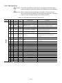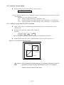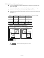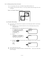
1
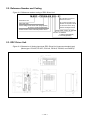
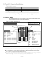
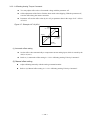
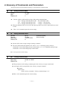
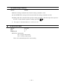
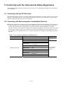
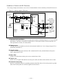
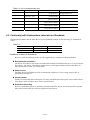
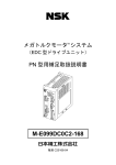
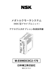
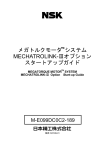
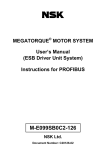
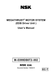
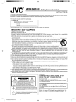
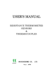
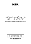
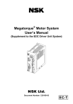
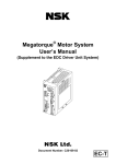
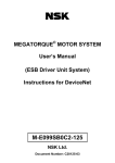
MEGATORQUETM MOTOR SYSTEM
User’s Manual
(EDC Driver Unit System)
Optional Driver Unit with Analog Interface
M-E099DC0C2-171
Document Number: C20171-01
Limited Warranty
NSK Ltd. warrants its products to be free from defects in material and/or workmanship which NSK
Ltd. is notified of in writing within, which comes first, one (1) year of shipment or 2400 total
operation hours. NSK Ltd., at its option, and with transportation charges prepaid by the claimant,
will repair or replace any product which has been proved to the satisfaction of NSK Ltd. to have a
defect in material and/or workmanship.
This warranty is the sole and exclusive remedy available, and under no circumstances shall NSK
Ltd. be liable for any consequential damages, loss of profits and/or personal injury as a result of
claim arising under this limited warranty. NSK Ltd. makes no other warranty express or implied,
and disclaims any warranties for fitness for a particular purpose or merchantability.
Copyright 1997 to 2008 by NSK Ltd., Tokyo, Japan
All rights reserved.
No part of this publication may be reproduced in any
form or by any means without permission in writing
from NSK Ltd.
NSK Ltd. reserves the right to make changes to any
products herein to improve reliability, function or design
without prior notice and without any obligation.
NSK Ltd. does not assume any liability arising out of the
application or use of any product described herein;
neither does it convey any license under its present
patent nor the rights of others.
Patents issued and patents pending.
“MEGATORQUE” is a registered trademark of NSK Ltd. in
Japan and that of NSK Corp. in the United States of America.
Contents
1. Introduction ------------------------------------------------------------ 1-1
2. Specifications---------------------------------------------------------- 2-1
2.1.System configuration ------------------------------------------------------------------ 2-1
2.2.Reference Number and Coding ----------------------------------------------------- 2-2
2.3.Dimension of EDC Drive Unit-------------------------------------------------------- 2-2
2.4. Functional Specifications ------------------------------------------------------------ 2-4
2.5. Specifications related to resolution ------------------------------------------------ 2-4
2.6. Control I/O Connector Specification----------------------------------------------- 2-5
2.6.1. Pin-Out (CN2) -------------------------------------------------------------------- 2-5
2.6.2. CN2 Signal List------------------------------------------------------------------- 2-6
3. Analog Input Function ----------------------------------------------- 3-1
3.1.Interfacing --------------------------------------------------------------------------------3-1
3.1.1.Analog Command Input---------------------------------------------------------3-1
3.2.Velocity Control Mode -----------------------------------------------------------------3-2
3.2.1.Velocity Control With RS-232C Command --------------------------------3-2
3.2.2.Velocity Control With Analog Command -----------------------------------3-3
3.2.2.1.Offsetting Analog Velocity Command---------------------------------3-4
3.3.Torque Control Mode ------------------------------------------------------------------3-6
3.3.1.Torque Control With RS-232C Command ---------------------------------3-6
3.3.2.Torque Control With Analog Command ------------------------------------3-7
3.3.2.1.Offsetting Analog Torque Command----------------------------------3-8
4. Glossary of Commands and Parameters------------------------4-1
5. Conformity with the International Safety Regulations ------- 5-1
5.1. Conformity with the EC Directives -------------------------------------------------- 5-1
5.2. Conformity with Electromagnetic Compatibility Directive --------------------- 5-1
5.3. Conformity with Underwriters Laboratories Standards ------------------------ 5-3
—i—
(Blank Page)
— ii —
1. Introduction
This manual describes an option of the Megatorque Motor System that consists of the
EDC Driver Unit with the Analog Interface. Please refer to the user’s manual of the
Megatorque Motor System (Document number: C20158) for other details.
For your safety, please be sure to read the user’s manual thoroughly before operating
the Megatorque Motor System.
— 1-1 —
(Blank page)
— 1-2 —
2. Specifications
2.1. System Configuration
Figure 2-1: System configuration for analog command
Handy Terminal
NSK
HANDY TERMINAL
1# 2$ 3< 4> 5% -+
6&
8(
9)
0?
A
B
C
D
E
G
H
I
J
K
L
M
N
O
P
Q
R
U
V
W
S
7‘
T
PLC*
Motor controller*
24 VDC
power supply*
EDC Driver Unit
.=
F
X
Y
Z
?
,
/
*
SHIFT
ESC
CTRL
BS
SP
ENT
RS-232C
communication
Control IO signal
Control
power
Main power
Single phase:
200 to 230 VAC
or
100 to 115 VAC
Analog signal
Megatorque Motor
Cable set
Resolver cable
Motor cable
* User shall provide these devices.
The optional parts listed below are not shipped with the Driver Unit.
Table 2-1:Optional parts lists
Name
System Reference Number
M-E014DCFS1-001
Connector
M-E014DCFS1-002
Driver Mounting
Brackets
M-E050DCKA1-001
Connector
for CN2
Connector
for CN5
Contents
Connector
:54306-5019(Molex)
Shell
:54331-0501(Molex)
Connector
:231-305/026-000(WAGO)
Wiring lever
:231-131(WAGO)
Qty 2, Includes screws (4-M3x8 countersunk Philips head)
Megatorque Motor System User’s Manual
(EDC Driver Unit System)
Optional Driver Unit with Analog Interface
Megatorque Motor System User’s Manual
(EDC Driver Unit System)
M-E099DC0C2-171
User’s Manual
M-E099DC0C2-158
— 2-1 —
2.2. Reference Number and Coding
Figure 2-2: Reference number coding of EDC Driver Unit
M-EDC – PS1006 A B 5 02 – 01
No code:without connectors,
blackets and manual
EDC Driver Unit
Motor size code
01: Provide connectors, fixing
blackets and Japanese manual
Power voltage A: 200 to 230 VAC (single phase)
C: 100 to 115 VAC (single phase)
02: Provid connectors, fixing
blackets and English manual.
Position sensor code B: Absolute position sensor
Design serial number: 02: Standard.
Function: 5: Standard
1: Analog Input(Optional)
C: CC-Link (Optional)
2.3. EDC Driver Unit
Figure 2-3: Dimension of Analog input type EDC Driver Unit (same as standard type)
(Motor type: PS1006, PS1012, PS1018, PS3015, PS3030, and PN2012)
— 2-2 —
Figure 2-4: Dimension of Analog input type EDC Driver Unit (same as standard type)
(Motor type: PS3060, and PS3090)
— 2-3 —
2.4. Functional Specifications
Table 2-2: Functional Specification
Control
mode
Input
signals
Output
signals
Velocity control
Torque control
Control Input
Position feedback
Control Output
Alarm functions
Monitoring functions
Communications
Data back-up
RS-232C serial communication, Analog command:±10V
RS-232C serial communication, Analog command:±10V
Emergency stop, Servo-on, Stop, Clear, Over travel limit, Integration OFF
Refer to “2.5.Specifications related to resolution”
Driver Unit ready, Warning, Servo-state,±Travel limit detection,
Under/Over velocity
RAM error,ROM error,System error,Interface error,ADC error,Emergency
stop,CPU error, Resolver Sensor error, Absolute position error, Motor cable
disconnect error, Excessive velocity, Resolver excitation amplifier alarm,
Commutation error,Over-heat, Main AC line over voltage, Excess current,
Control AC line under voltage, Power module alarm,Software thermal error, Main
AC line under-voltage, Over travel limit
Analog monitor × 2ch(Motor velocity, Motor velocity command, Motor velocity
error, Torque command, Current command, Thermal load)
RS-232C communications monitor (Position data, Alarm messages,
Servo parameter, etc)
RS-232C serial communications (synchronous,9600[bps])
EEPROM (The parameter can be rewritten 100,000 times)
2.5. Specification related to resolution
Table 2-3: resolution specification
Item
Resolver Resolution
Resolver Accuracy
Specifications
2,621,440[counts/revolution] ※1
90[arc-sec] compatible※1
(when environmental temperature of 25±5[℃])
Position feed back signal output format
ΦA/ΦB/ΦZ Line driver
20,480[pulses/revolution](default setting)
Resolution of Position feedback signal
Phase A ,A
(Quadrupled:81920)
Phase B ,B
Up to 1,310,720[pulses/revolution] can be set※2
(Quadrupled:5242880)
(Maximum frequency remains 781 [k Hz])
80[pulses/revolution]
Phase Z ,Z
※1
Due to the speed limit of feedback signal and the resolution of analog command, performance such as high
speed and high precision which are expected by using standard type EDC Driver Unit or CC-Link Type EDC
Driver Unit may not exhibited by external controller.
※2
As the maximum frequency is 781 [k Hz], the setting of the resolution limits the maximum velocity.
The maximum velocity [s-1] = 781[kHz] / phase A, and B resolution.
— 2-4 —
2.6. Control I/O Connector Specifications
Table 2-4:Mating connector
Connector
Manufacturer and model
Driver Unit’s connector
Molex 52986-5071
Mating connector (user’s device side)
Molex 54306-5019
Mating connector shell (user’s device side)
Molex 54331-0501
Use shielded cable for wiring of the CN2 connector and be sure to use twisted cables for the
position feed back signals. Wiring length shall be short as possible. (2[m] maximum)
2.6.1.Pin-Out(CN2)
The pin-out arrangement below is for the shipping set. The function of each signal port may be
changed by the function setting of control Input/Output ports.
Figure 2-5: CN2 pin out (shipping set)
Output dedicated to safety function
Input dedicated to safety function
DRDY
NRM
EMST :Emergency stop
General input
EMST
ACLR
OTP
OTM
SVON
RUN
STP
PRG0
PRG1
PRG2
PRG3
PRG4
IOFF
NONE
:Emergency stop
:Alarm clear
:Travel limit, + direction
:Travel limit, - direction
:Servo on
:Program start
:Stop
:Internal program channel selection 0
:Internal program channel selection 1
:Internal program channel selection 2
:Internal program channel selection 3
:Internal program channel selection 4
:Integration off
:(Set to a non-function port)
2
DC24
4
ACLR
6
OTM
8
IOFF
10
-
12
-
14
-
16
-
18
-
20
-
22
-
24
-
1
DC24
3
EMST
5
OTP
7
SVON
9
STP
11
-
13
-
15
-
17
-
19
-
21
-
23
-
25
-
27
COM
29
WRN
31
OTMA
33
TVU
35
-
37
*CHA
39
*CHB
41
*CHZ
43
SGND
45
AIN47
-
49
-
26
COM
28
DRDY
30
OTPA
32
SVST
34
TVO
36
CHA
38
CHB
40
CHZ
42
-
44
AIN+
46
-
48
-
50
-
:Driver Unit ready
:Normal
General output
DRDY
WRN
OTPA
OTMA
SVST
BUSY
ZONEA
ZONEB
ZONEC
TVU
TVO
TTU
TTO
TJU
TJO
OTXA
NRM
NONE
:Driver Unit ready
:Warning
:Travel limit detection, + direction
:Travel limit detection, - direction
:Servo state
:In operation
:Zone A
:Zone B
:Zone C
:Velocity under
:Velocity over
:Torque command under
:Torque command over
:Thermal loading under
:Thermal loading over
:Travel limit ditection, ±direction
:Normal
:(Set to a non-function port)
Pin number 3 and Pin number 28 are the dedicated ports to the safety function input and output respectively.
You cannot change the function setting to the Pin number 3: EMST input [Emergency stop]. You may
only set the logic of the connector and the stability timer to it.
You can only change the function of the Pin number 28: DRDY output [Driver Unit ready] to the function
NRM (normal) output. You cannot set the output logic and the stability timer to it.
— 2-5 —
2.6.2. CN2 Signal List
! Caution : Follow the specification documents for the specially ordered System
when its settings of Inputs and Outputs are different from the standard.
! Caution :Never connect the idle pins that are instructed as “Do not connect.”
Do not disconnect the idle pins at the master controller (PLC, etc) side
after you have connected all pins of the CN2 connector.
Table 2-5: CN2 signal name and function (Shipping set)
Pin
No
Port
code
Signal
code
Contact
logic
1
-
DC24
-
2
-
DC24
-
3
PI0
EMST
Normally
closed
Emergency stop
4
PI1
ACLR
Normally
open
Alarm clear
5
PI2
OTP
Normally
closed
Over travel limit, + direction
6
PI3
OTM
Normally
closed
Over travel limit, - direction
7
PI4
SVON
Normally
open
Servo-on
8
PI5
IOFF
Normally
open
Integration OFF
Terminates velocity integration control.
9
PI6
STP
Normally
open
Stop
Stops positioning operation and execution of
the program.
10
-
-
-
11
-
-
-
12
-
-
-
13
-
-
-
14
-
-
-
15
-
-
-
16
-
-
-
17
-
-
-
18
-
-
-
19
-
-
-
20
-
-
-
21
-
-
-
22
-
-
-
23
-
-
-
24
-
-
-
25
-
-
-
Input
Input
Output
Signal name
24 VDC external power supply
24 VDC external power supply
Function
External power supply for input signal
External power supply for input signal
Terminates positioning operation and the
Motor stops by the dynamic break.
Clears warning.
(Do not connect)
(Do not connect)
(Do not connect)
(Do not connect)
(Do not connect)
(Do not connect)
(Do not connect)
(Do not connect)
(Do not connect)
(Do not connect)
(Do not connect)
(Do not connect)
(Do not connect)
(Do not connect)
(Do not connect)
(Do not connect)
— 2-6 —
If OTP goes active, the Motor servo is
locked in the CW direction.
If OTM goes active, the Motor servo is
locked in the CCW direction.
If SVON goes active, the servo turns on and
the System waits for a command to be
entered.
-
Table 2-5 (continued): CN2 signal name and function (Shipping set)
Output
Input Pin
Output No.
Port
code
Signal
code
Contact
logic
26
–
COM
–
27
–
COM
–
28
PO0
DRDY
Positive
Driver Unit ready
29
PO1
WRN
Negative
30
PO2
OTPA
Negative
Warning
Over travel limit (+ direction)
detected
31
PO3
OTMA
Negative
32
PO4
SVST
Positive
33
PO5
TVU
Positive
34
PO6
TVO
Positive
35
–
–
–
36
–
CHA
–
37
–
*CHA
38
–
CHB
39
–
*CHB
40
–
CHZ
41
–
42
–
*CHZ
–
43
–
SGND
44
–
45
–
46
–
47
–
48
–
49
–
50
–
AIN+
AIN–
–
–
–
–
–
–
–
–
–
–
–
–
–
–
–
–
–
–
Signal name
Output signal common
Output signal common
Over travel limit (- direction)
detected
Servo state
Velocity, under
Velocity, over
(Do not connect.)
Position feedback signal øA
Position feedback signal ø*A
Position feedback signal øB
Position feedback signal ø*B
Position feedback signal øZ
Position feedback signal ø*Z
(Do not connect.)
Signal ground
Analog command (+)
Analog command (-)
(Do not connect.)
(Do not connect.)
(Do not connect.)
(Do not connect.)
(Do not connect.)
— 2-7 —
Function
Common for output signal.
Reports that the Motor is ready to rotate.
(Those pins are open when the Motor is not
ready or an alarm occurs.)
Warns abnormality in the System.
Reports the output of over travel limit
(software and hardware) in the plus direction.
Reports the output of over travel limit
(software and hardware) in the minus
direction.
Reports the state of servo.
Reports condition of velocity against the
threshold value.
–
A pulse signal that reports the number of
rotations of the Motor.
Free setting of output resolution in øA/øB
phase is available.
–
Ground for the position feedback signal.
+/- 10[VDC] input for analog velocity or
torque control.
–
–
–
–
–
(Blank page)
— 2-8 —
3. Analog Input function
!
Caution:Constrain of motor speed
・Each motor type has its maximum speed. Check the maximum speed in the
specification sheet.
・The parameter VL (Velocity limiter) depends on parameter FR (Feedback signal
resolution).
!
Caution:Positioning control by external controller
・Due to the speed limit of feedback signal and the resolution of analog command,
performance such as high speed and high precision which are expected by using
standard type EDC Driver Unit or CC-Link Type EDC Driver Unit may not exhibited by
external controller.
3.1. Interfacing
3.1.1. Analog Command Input
Applied input: AIN +, AIN –
Table 3-1: Specifications of analog command input
Item
Max. input voltage
Input impedance
Maxi. input current
ADC resolution
Effective resolution
Specification
± 10 [VDC]
20 [ kΩ]
0.5 [mA]
12 [bits]
Typical 10 [bits]
Offset error
±13 [ %] of maximum input voltage
Figure 3-1:Analog input specification
20 [kΩ]
AIN +
–
AIN –
+
User’s controller side
Driver Unit side
— 3-1 —
3.2. Velocity Control Mode
Parameter SL2 sets the control mode to velocity control.
SL1: Torque control mode
SL2: Velocity control mode
SL3: Inhibit
Velocity control via the RS-232C command or the analog command may be selected in the velocity
control mode.
Parameter AC selects the way of control.
AC0 : Analog command invalid. DC command is valid.
AC1 : Analog command valid. When analog velocity command is +: CW direction
AC–1 : Analog command valid. When analog velocity command is +: CCW direction
3.2.1. Velocity Control with RS-232C Command
Motor velocity may be controlled directly through the RS-232C command in the velocity
control mode.
Parameter AC (AC0) sets validity of DC command.
Inputting
D
C
(data)
ENT
will have the Motor controlled with the velocity that is proportional to the data.
Relation between the data of DC command and the velocity is shown in Figure 3-2.
Figure 3-2: DC command VS the velocity
Rotational speed
-1
10 [s ]
-32 767
+32 767
DC command
-1
-10 [s ]
! Caution : AS DI parameter reverses the sign of coordinate, the polarity of the DC
command is reversed as well. DI parameter is set to “0” in shipping.
:Please confirm the speed of the motor.
— 3-2 —
3.2.2. Velocity Control with Analog Command
Velocity of the Motor may be directly controlled with the analog velocity command in the
velocity control mode.
Voltage range of the analog command is ± 10V. Offset adjustment is possible setting
parameter AF. (Refer to “3.2.2.1. Offsetting Analog Velocity Command.”)
Parameter AC selects the polarity of command voltage. (Refer to Table 3-2.)
Relation between the command voltage and the velocity may be selected with parameter AG.
(See Figure 3-3.)
Table 3-2: Rotating direction relater to DI,AC and the polarity of Command voltage
DI setting
0
0
0
0
1
1
1
1
AC setting
1
1
–1
–1
1
1
–1
–1
Command voltage
+
–
+
–
+
–
+
–
Rotating direction
CW
CCW
CCW
CW
CCW
CW
CW
CCW
Figure 3-3: Command voltage and velocity (DI=0)
• Porality: + for CW direction
(AC1)
• Porality: + for CCW direction
(AC-1)
Rotational speed
-1
Rotational speed
-1
10[s ]
10[s ]
Input voltage
+ 10 [V]
- 10 [V]
+ 10 [V]
- 10 [V]
Input voltage
-1
-10[s ]
-1
-10[s ]
AG = 0.5
AG = 1.0
AG = 2.0
! CAUTION :Please confirm the speed of the motor.
— 3-3 —
3.2.2.1. Offsetting Analog Velocity Command
You may adjust offset value of command voltage with the parameter AF.
Parameter AF sets the offset value by “ 0.3 mV” per parameter data in the range of AF–6552
to AF6552.
Figure 3-4: Example: Setting AF-10 (AC1)
Rotational speed
-1
10 [s ]
Input Voltage
+ 10 [V]
- 10 [V]
- 3 [mV]
-1
- 10 [s ]
(1) Automatic offset setting
Set the offset value automatically to compensate current analog input, which is caused by the
drift, to 0 (zero).
(1)
Connect the master controller and the Driver Unit, and then input analog velocity
command 0 (zero).
(2)
Input the password. The acknowledgement will be returned.
(3)
/
N
S
O
N
ENT
F
/
SP
:/NSK ON
NSK ON
:_
S
T
:AF/ST_
Input as
A
(4)
K
Pressing the ENT key sets the offset value automatically. The set value of AF will
be on the screen.
:AF/ST
AFxx
:_
ENT
Unit of setting value is [0.3mV].
If the offset value is too much, it indicates as “RANGE OVER?”.
won’t be changed.
— 3-4 —
However, the offset value
(2) Manual offset setting
Set offset value with the analog command monitor.
(1)
Take a memo of setting on polarity of the analog command AC, and then change those settings to
AC1.
(2)
Connect the master controller and the Driver Unit and input the velocity command of 0 (zero).
(3)
Type as shown below and monitor the analog command.
R
(4)
A
/
R
P
:RA/RP_
When the ENT key is pressed, the current analog command due to the drifting will be
shown in the screen repeatedly. Indication of 2 , as shown in the screen below, denotes that
the offset to the command voltage shall be 0.6 mV ( 0.3[mV] × 2).
:RA/RP
ENT
2_
(5)
Confirm the result and press the BS key. Otherwise the next command won’t be accepted.
:RA/RP
BS
2
:_
(6)
(7)
Input the password. The acknowledgement will be returned.
/
N
S
O
N
ENT
SP
:/NSK ON
NSK ON
:_
Execute the following commands. Be sure to input the opposite sign as it was monitored by
the RA command.
A
(8)
K
F
-
2$
ENT
:AF-2
:_
Reset the analog command polarity AC to the setting as noted at the step (1).
— 3-5 —
3.3. Torque Control Mode
Parameter SL1 selects the torque control mode.
SL1: Torque control mode
SL2: Velocity control mode
SL3: Inhibit
Torque control via the RS-232C command or the analog command may be selected. Parameter
AC selects the way of control.
AC0 : Analog command invalid. DC command is valid.
AC1 : Analog command valid. When analog torque command is +: CW rotation
AC–1 : Analog command valid. When analog torque command is +: CCW rotation
3.3.1. Torque Control with RS-232C Command
You may control directly the motor output torque with RS-232C command in the torque
control mode.
Set the parameter AC (AC0) to make the DC command valid.
Input as
D
C
(data)
ENT
to control the motor with torque proportional to the parameter data.
Relation between the data of DC command and the motor output torque is shown in Figure
3-5.
Figure 3-5: DC command VS the motor output torque
CW
Max. torque
- 32 767
+32 767
DC commnad
CCW
Max. torque
— 3-6 —
3.3.2. Torque Control with Analog Command
You may control directly the output torque of the Motor with analog torque command in the
torque control mode.
Voltage of analog torque command is ± 10V. Offsetting analog command is possible
setting parameter AF. (Refer to “3.3.2.1. Offsetting Analog Torque Command.”
Parameter AC selects the polarity of command voltage. (See Table 3-3.)
Relation between the command voltage and the output torque of the Motor may be
changed with parameter AG.
(Refer to Figure 3-6.)
Table 3-3: Rotating direction relater to DI,AC and the polarity of Command voltage
DI setting
0
0
0
0
1
1
1
1
AC setting
1
1
-1
-1
1
1
-1
-1
Command voltage
+
–
+
–
+
–
+
–
Rotational direction
CW
CCW
CCW
CW
CCW
CW
CW
CCW
Figure 3-6: Command voltage and output torque (DI=0)
• Porality: + for CW direction
(AC1)
• Porality: + for CCW direction
(AC-1)
CW
CW
Max. torque
Max. torque
Input Voltage
+ 10[V]
- 10 [V]
+ 10 [V]
- 10[V]
Input Voltage
CCW
Max. torque
AG = 0.5
AG = 1.0
AG = 2.0
— 3-7 —
CCW
Max. torque
3.3.2.1. Offsetting Analog Torque Command
You may adjust offset value of command voltage with the parameter AF.
Offset adjustment of the Driver Unit has been made at the shipping. With the parameter AF,
reset the offset along the master controller.
Parameter AF sets the offset value by 0.3 mV per parameter data in the range of AF –6552 to
AF 6552.
Figure 3-7: Example: AF-10 (AC1)
CW
Max. torque
- 10 [V]
- 3 [mV]
+ 10 [V]
Input voltage
CCW
Max. torque
(1) Automatic offset setting
Set the offset value automatically to compensate current analog input, which is caused by the
drift, to 0 (zero).
Refer to (1) Automatic offset setting in “3.2.2.1.Offsetting Analog Velocity Command.”
(2) Manual offset setting
Adjust offsetting manually with the analog command monitor.
Refer to (2) Manual offset setting in “3.2.2.1. Offsetting Analog Velocity Command.”
— 3-8 —
4. Glossary of Commands and Parameters
The password must be entered before inputting a command that is marked with
AC
.
: Analog Command Mode
Format
Data
Shipping set
: AC data
: -1, 0, 1
:1
Sets the validity (valid/invalid) and sign of the analog command input.
AC0 : Analog command input invalid. DC command is valid.
AC1 : Analog command input valid.
Voltage +: CW direction
AC-1 : Analog command input valid.
Voltage +: CCW direction
When the parameter DI is set to reverse the sign of position scale, above signs shall be reversed
as well.
TS0 or ?AC command reports the current setting.
AF
: Analog Command Offset
Format1
Format2
Data range
Shipping set
: AF/ST
: AF data
: - 6552 to 6552
:0
Automatic setting
Manual setting
Sets the offset value on input voltage of analog command.
For more details about the parameter AF, refer to “3.2.2.1. Offsetting Analog Velocity
Command” in case of the analog velocity control mode, or “3.3.2.1. Offsetting Analog Torque
Command” in case of the analog torque control mode.
TS0 or ?AF reports the current setting.
AG
: Analog Command Gain
Format
Data range
Shipping set
:
AG data
: 0.0001 to 2.0000
:1
This parameter sets the analog command gain in the velocity or torque control mode.
Actual gain value is proportional to the velocity or torque command.
Example
When AG0.5:
Actual velocity command = Velocity command input × 0.5
TS0 or ?AG command reports the current setting.
— 4-1 —
AFP
: Analog Command Filter, Primary
Format
Data range1
Data range2
Shipping set
: AFP data
:0
: 10 to 1000
: 200
Primary analog command filter is OFF
[Hz]
This parameter sets the low-pass filter against the analog command.
TS0 or ?AFP command reports the current setting.
AFS: Analog Command Filter, Secondary
Format
Data range1
Data range2
Shipping set
: AFS data
:0
: 10 to 1000
:0
Secondary analog command filter is OFF
[Hz]
This parameter sets the low-pass filter against the analog command.
TS0 or ?AFS command reports the current setting.
DC: Digital Command Mode
Format
Data range
Torque control mode
Velocity control mode
Shipping set
: DC data
: – 32 767 to 32 767 (CW in positive command)
: – 32 767 to 32 767 (CW in positive command)
:0
This command is to input directly the operation command through the RS-232C communication
interface in velocity or torque control mode.
However, the use of this command shall be limited to an ordinal operation, or a testing operation
of the Motor due to sluggish response.
If DC command is inputted when an analog command (AC command) is valid, “DC
INHIBITED” message will be given and the command will be invalidated.
The data of this command will be cleared to “0” in the following state.
1)
Servo off
2)
Emergency stop
3)
Over travel limit
4)
Control mode is switched.
5)
Analog command is valid.
6)
MS command is executed, or STP input is ON.
! Caution : When the sign of the position scale is reversed with DI command, the
sign of DC command will be reversed as well.
— 4-2 —
RA: Read Analog Command
Format
: RA/RP
Reads an analog command value when the analog command is valid.
“RA INHIBITED” message will be returned when the analog command is invalid.
Adding /RP to RA command will report the reading repeatedly, while RA input alone reports in
one shot. To quit from the repetitive readings, press the BS key.
The report is a decimal number in –32 767 to 32 767.
SL:Set Control Mode
Format
Data
Shipping set
: SL data
: 1, 2
:2
Sets the control mode.
SL1 : Torque control mode
SL2 : Velocity control mode
TS0 or ?SL command reports the current setting.
— 4-3 —
(Blank page)
— 4-4 —
5. Conformity with the International Safety Regulations
The Megatorque Motor Systems conform to the EC Directives (CE Marking) and Underwriters Laboratory
(UL) regulations.
5.1. Conformity with the EC Directives
The Megatorque Motor System is a machine component that conforms to provisions of the EC Low Voltage
Directive. This will help a user in easy conformity with the EC Directives (CE marking) of a machine into
which the Megatorque Motor System is incorporated.
5.2. Conformity with Electromagnetic Compatibility Directive
The Motor and the Driver Unit of a model of the Megatorque Motor System, which has a four-meter long
connecting cable, were tested under the specific conditions, such as their installing distance and wiring
routing. The model has been confirmed for its conformity with the related regulations of the EMC
Directive. However, your actual use conditions for wiring and installations won’t be the same as our tested
model. Thus, you have to check your machine, especially on the radiated noise and conducted noise, for
the conformity with the EMC Directive as a complete machine after installation of the Megatorque Motor
System.
Table 5-1: List of relevant standards for EMC Directive
Item
Megatorque Motor
Motor / Driver Unit
Conformed regulation
EN60034-1
EN50178
EN55011
EN55011
Low Voltage
Directive
: Group1, Class A Conducted noise
: Group1, Class A: Radiated noise
: Immunity standard for industrial
EN61000-6-2
environments
: Electro static discharge
EN61000-4-2
: Radio-frequency electromagnetic
EN61000-4-3
field
: Electric fast transit burst
EN61000-4-4
: Lightning surges
EN61000-4-5
: Radio frequency conducted
EN61000-4-6
disturbance
: Power frequency magnetic field
EN61000-4-8
EN61000-4-11 : Voltage dips and short interruption
— 5-1 —
Electromagnetic
Compatibility
Directive
Conditions to Conform with EC Directives
The wiring example shown below is one of our recommendations for the conformity with the EC Directives.
Figure 5-1: Wiring diagram (Example)
AC power
source
Circuit
breaker
EDC Driver Unit
Noise
filter
CN5
Control
power
L
N
Surge
absorber
Ferrite
core 1
(3 turns)
Ferrite
core 2
(2 turns)
L
N
Ferrite
core 3
(1 turn)
Main
power
PS Series
Megatorque Motor
Resolver
CN3
N
Protective
ground
Ferrite core 3
(2 turns)
CN1
Inside of
control
panel
CN4
Ferrite
core 3
(1 turn)
Handy
Terminal
CN2
Ferrite
core 3
(2 turn)
Motor
to controller
Environmental conditions
The Driver Unit must be used in the environmental condition of Pollution Degree1 or 2 as specified by
IEC60664-1. The Driver Unit shall be installed into a control panel with the structure that does not
allow penetration of water, oil or dust (IP54).
Power source
The EDC Driver Unit shall be used in the environmental condition of “Over-voltage category III” as
specified by IEC60664-1.
Circuit breaker
Install a circuit breaker that conforms to IEC standard and UL safety standard between the power
source and the Driver Unit.
Noise filter
Install a noise filter between the power source and the Driver Unit.
Ferrite core
Ferrite cores for signal cable shall be set to the power cable, the Motor cable and the resolver cable.
Protective Grounding
Be sure to ground the protective grounding terminal of the EDC Driver Unit to the protective ground
(PE) of the control panel for a measure against electrical shock.
— 5-2 —
Table 5-2: List of recommended part
Item
Specification
Circuit breaker
Rated current: 15 A
Noise filter
Single phase:
250 VAC, 10 A
Surge absorber
–
Ferrite core 1
-
Ferrite core 2
-
Ferrite core 3
–
Manufacturer
Remarks
Single phase: EA32AC-10
Conforms to IEC regulations
(Fuji Electric) and approved by UL
FN2070-10/06
(SHAFFNER)
R-A-V781BWZ-4
(Okaya electric)
E04RA400270150
(Seiwa Electric MFG)
E04SR301334
For the Handy Terminal
(Seiwa Electric MFG)
E04SR21132
(Seiwa Electric MFG)
5.3. Conformity with Underwriters Laboratories Standards
The Megatorque Motor and the EDC Driver Unit are qualified products for the following UL Standard for
safety.
Table 5-3
Subject
Megatorque Motor
Driver Unit
Qualified regulation
UL1004
UL508C
File No.
E216970
E216221
Conditions to Meet UL Standards
Be sure to meet the following as they are the supplementary conditions for the qualification.
Environmental conditions
The Driver Unit must be used in the environmental condition of Pollution Degree1 or 2 as specified by
IEC60664-1. The Driver Unit shall be installed into a control panel with the structure that does not
allow penetration of water, oil or dust (IP54).
Power source
The EDC Driver Unit shall be used in environmental condition of “Over-voltage category III” as
specified by IEC60664-1.
Circuit breaker
Install a circuit breaker that conforms the UL safety standard between the power source and the Driver
Unit. (Please refer to Table 2 above for the specifications.)
Protective Grounding
Be sure to ground the protective grounding terminal of the EDC Driver Unit to the protective ground
(PE) of the control panel for a measure against electrical shock.
— 5-3 —
(Blank Page)
— 5-4 —
MEGATORQUETM MOTOR SYSTEM
User’s Manual
(EDC Driver Unit System)
Analog Driver Unit with Analog Interface
Document Number: C20171-01
Jun 20, 2008
1st Edition
NSK Ltd.
1st Printing
1st Edition, 1st Printing
Jun 20, 2008
Document Number: C20171-01