1
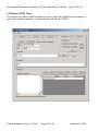
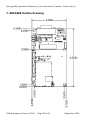
Installation and Operating Instructions
For
Synergy488
with
Environmental Chamber Control Firmware
TE1579
Tidal Engineering Corporation (c) 2004
Doc. No. TE1579 Revision E
Tidal Engineering Corp (c) 2004
Page 1 of 40
September 2004
Synergy488_Application Manual_for_Environmental_Chamber_Control_Rev_E
Revisions
Rev
Prelimin.
B
C
Date
2 April
2004
7 June
2004
10 June
2004
Revision
Preliminary
Added Modbus capability and enhanced setup instructions.
Firmware TE1579_2_0.
Added Detailed instructions for client connections including
GPIB addressing and TCPIP setup. Also added Yokogawa
wiring.
Renamed document:
Synergy488_Application_Manual_for_Environmental_Chamber_Control_Rev_C.d
oc
D
25 June
2004
Added Yokogawa and BlueM Pro PC Link Communication
setup instructions for 550 and 750
E
20 Sept.
2004
New release for Firmware TE1579_4_1.
Added Partlow MIC 1460 and MIC 1462 Communication
setup. Corrected typographical errors and other errors.
Tidal Engineering Corp (c) 2004
Page 2 of 40
September 2004
Synergy488_Application Manual_for_Environmental_Chamber_Control_Rev_E
Synergy488 Manual for Environmental Chamber Control
For
TE1579 Environmental Chamber Control Firmware with GPIB, Serial and Ethernet
Communications
Document Number TT1579
©2004 Tidal Engineering Corporation. All rights reserved.
Notice to Users
TIDAL ENGINEERING PRODUCTS ARE NOT AUTHORIZED FOR USE AS CRITICAL
COMPONENTS IN LIFE-SUPPORT DEVICES OR SYSTEMS UNLESS A SPECIFIC WRITTEN
AGREEMENT REGARDING SUCH USE IS ENTERED OBTAINED FROM TIDAL: ENGINEERING
PRIOR TO USE.
Life-support devices or systems are devices or systems intended for surgical implantation into the body or to
sustain life, and whose failure to perform, when properly used in accordance with instructions for use
provided in the labeling and user’s manual, can be reasonably expected to result in significant injury. No
complex software or hardware system is perfect. Bugs are always present in a system of any size. In order to
prevent danger to life or property, it is the responsibility of the system designer to incorporate redundant
protective mechanisms appropriate to the risk involved. All Tidal Engineering products are 100 percent
functionally tested. Additional testing may include visual inspections. Specifications are based on
characterization of tested sample units rather than testing over temperature and voltage of each unit.
Additional testing or burn-in of a system is available by special order. Tidal Engineering reserves the right to
make changes and improvements to its products without providing notice.
Trademarks
TIDAL ENGINEERING IS A REGISTERED TRADEMARK OF TIDAL ENGINEERING CORPORATION.
Tidal Engineering Corporation
2 Emery Ave
Randolph, NJ 07869
Tel: 973-328-1181
Fax: 973-328-2302
www.TidalEng.com
Tidal Engineering Corp (c) 2004
Page 3 of 40
September 2004
Synergy488_Application Manual_for_Environmental_Chamber_Control_Rev_E
Table of Contents
Revisions ............................................................................................................................................................ 2
1. Introduction .................................................................................................................................................... 5
1.1 Synergy488 Configurations...................................................................................................................... 6
1.2 Synergy488 Accessories........................................................................................................................... 7
2. Controller Setup.............................................................................................................................................. 8
2.1 VersaTenn III Setup ............................................................................................................................... 11
2.2 Watlow 942 Setup .................................................................................................................................. 12
2.3 Watlow F4 .............................................................................................................................................. 13
2.4 Yokogawa/BlueM................................................................................................................................... 14
2.5 Partlow MIC 1460 and MIC 1462.......................................................................................................... 21
3. Synergy488 Commands................................................................................................................................ 24
3.1 Synergy488 Configuration Commands .................................................................................................. 24
3.2 Identify Command.................................................................................................................................. 24
3.3 Save Command....................................................................................................................................... 24
3.4 Recall Command .................................................................................................................................... 25
3.5 TCPIP Properties Command .................................................................................................................. 25
4. Synergy488 Modbus Command Set............................................................................................................. 26
4.1 Channel Command ................................................................................................................................. 26
4.2 Read Register Command ........................................................................................................................ 26
4.3 Write Register Command ....................................................................................................................... 27
4.4 Write Register Block Command ............................................................................................................ 27
4.5 Write Modbus Timeout Command......................................................................................................... 27
5. Synergy488 Connection Summary:.............................................................................................................. 28
5.1 RS-232 Client Connection Setup............................................................................................................ 29
5.2 GPIB Client Connection Setup............................................................................................................... 30
5.3 Ethernet Client Connection Setup .......................................................................................................... 32
6. SimpleComm................................................................................................................................................ 35
6.1 RS-232.................................................................................................................................................... 36
6.2 GPIB ....................................................................................................................................................... 37
6.3 Ethernet (TCPIP) Telnet......................................................................................................................... 38
7. SBC488E Outline Drawing .......................................................................................................................... 39
8. About Tidal Engineering .............................................................................................................................. 40
Tidal Engineering Corp (c) 2004
Page 4 of 40
September 2004
Synergy488_Application Manual_for_Environmental_Chamber_Control_Rev_E
1. Introduction
This manual covers the Synergy488, Tidal Engineering Corporation’s SBC488E with
Application specific firmware TE1579-4
This firmware is designed to provide GPIB, RS-232 and Ethernet communications
capabilities to the following Controllers:
Tenney VersaTenn II and VersaTenn III
Watlow 942 and F4 controllers
Yokogawa UP750 and UP550
BlueM Pro750 and Pro550
Partlow MIC14 60 and MIC 1462
Other ASCII and ModbusRTU controllers can also be supported. Consult factory for
specifics.
Contact the factory for the availability of other firmware to support different
controllers
The SBC488E monitors and receives commands from client computers on all three
input ports simultaneously. The commands are sent to the chamber controller on a
first come-first serve basis.
The determination of ASCII or Modbus RTU controller type is made using the Mode
jumpers at P13.
Tidal Engineering Corp (c) 2004
Page 5 of 40
September 2004
Synergy488_Application Manual_for_Environmental_Chamber_Control_Rev_E
1.1 Synergy488 Configurations
The Synergy488 Environmental Test Chamber control firmware is P/N TE1579. There
are two hardware configurations, SBC488E P/N TE1267-1 and TE1267-3. The
following list .
Firmware
Revision
Description
TE1579_2_0
1. Added Modbus-RTU Master for F4 over GPIB and Telnet
TCPIP to port 5000. Install Jumper on Mode 0 (First
jumper).
TE1579_3_3
1. Added support for PClink for Pro550 and Pro750, Yokogawa
550 and 750 controllers. Install Jumper on Mode 1 (Second
jumper).
TE1579_4_1
1. Added support for Partlow 1462 (Modbus) over GPIB, RS232 and Telnet (TCPIP to port 5000). Jumper on Mode 2
(Third jumper).
2. Checks GPIB address dipswitch all the time, not just at
power up.
Tidal Engineering Corp (c) 2004
Page 6 of 40
September 2004
Synergy488_Application Manual_for_Environmental_Chamber_Control_Rev_E
1.2 Synergy488 Accessories
P/N
TE1435-1
Description
Wall Transformer:
Input: 115 VAC,l 60 Hz
Output: 9 Volts DC, 500 mA
Connector: Molex 10-11-2023
TE1640-1
Wall Transformer:
Input: 90-285 VAC, 47 to 63Hz
Output: 9 Volts DC, 500 mA
Connector: Molex 10-11-2023
Note: This part includes a set of
mains adapters for most US and
International applications (see
photo)
Connector Assembly:
P1: 10-Position Header
P2: 10-Position Terminal Block
P3: 15-position Male (VTIII)
Connect to any controller
TE1602
TE1595
TE1596
Serial Ribbon Cable:
Length: 6 ft.
P1: 10 Position IDC Connector
P2: 10 Position IDC Connector
P3: 9 Position Female DSUB
Note: DSUB is wired to connect
direct to PC serial port.
GPIB Ribbon Cable:
Length: 6 ft.
P2: 26 Position IDC Connector
PX: GPIB Connector
Tidal Engineering Corp (c) 2004
Page 7 of 40
September 2004
Synergy488_Application Manual_for_Environmental_Chamber_Control_Rev_E
2. Controller Setup
This section describes the configuration of the Chamber Controller and the setup of
the Synergy488 for communications. SBC488E with TE1579 firmware accepts client
commands over three ports, RS-232 (P6), GPIB (P2/P8) and Ethernet (J4) and passes
the commands to a controller or processes SBC488E configuration commands itself.
Controller Communications parameters are listed in the table below:
Controller
Chamber Controller Setup
Wiring
Controller
Comm. Settings
SBC488E
Jumpers
VersaTenn III
Use TE1602
adapter.
Adapter P3
connects
directly to VTIII
A01.
9600 Baud
7 Data bits
Odd Parity
(1 Stop Bit)
Mode 0-No
Mode 1-No
Mode 2-No
Watlow 942
Use TE1602
adapter.
See wiring in
next section.
9600 Baud
7 Data bits
Odd Parity
1 Stop Bit
Mode 0-No
Mode 1-No
Mode 2-No
Watlow F4
Use TE1602
adapter.
See wiring in
next section.
19200 Baud
8 Data Bits
No parity
1 Stop Bit
Mode 0-YES
Mode 1-No
Mode 2-No
Yokogawa/BlueM 750 and 550
Use TE1602
adapter.
See wiring in
next section.
9600 Baud
8 Data Bits
No parity
1 Stop Bit
Chamber Controller Setup (Continued)
Tidal Engineering Corp (c) 2004
Page 8 of 40
Mode 0-No
Mode 1-YES
Mode 2-No
September 2004
Synergy488_Application Manual_for_Environmental_Chamber_Control_Rev_E
Controller
Wiring
Controller
SBC488E
Comm. Settings
Jumpers
Partlow MIC 1460 and MIC 1462
Use TE1602
adapter.
See wiring in
next section.
9600 Baud
Tidal Engineering Corp (c) 2004
Page 9 of 40
8 Data Bits
Even parity
1 Stop Bits
Mode 0-No
Mode 1-No
Mode 2-YES
September 2004
Synergy488_Application Manual_for_Environmental_Chamber_Control_Rev_E
SBC488E Diagram
P13 - Config Jumpers
GPIB
P2-GPIB
J4 - RJ45
Ethernet
LEDS
P8-GPIB
P1-Power
Talk/Listen
LEDS
Client
Personal
Computer
P5-RS-485
Port to
RS-485
Controllers
P7-RS-232
Port to
Controllers
P6-RS-232
Port to PC
19200-N81
Synergy488E Communication Adapter
J4- 10/100
BaseT Ethernet
SBC488E
CPU
RS-232
Controller
P7- RS-232
9600, 7O1
P8 or P2
GPIB
P5- RS-485
19200, 8N1
P6 - RS-232
19200, N81
RS-485
controllers
Tidal Engineering Corp (c) 2004
Page 10 of 40
September 2004
Synergy488_Application Manual_for_Environmental_Chamber_Control_Rev_E
2.1 VersaTenn III Setup
Wiring to SBC488E/Wiring adapter
TE1602
TE1602 Adapter
SBC488E
SBC488E
P7
RS-232
10 Cond. Ribbon
P1
WATLOW III
942
VersaTenn
P3
A01
Watlow 942 Wiring to TE1602 Wiring adapter (Note that TE1602 adapter is designed
to plug directly onto the VTIII communications connector A01)
SBC488E-P7 to
Adapter-P2
TX
Comms Gnd
RX
Comms Gnd
SBC488E-P7 to
Adapter-P2
3
9
5
9
VersaTenn III
Function
TXRX+
RXComms Gnd
Controller
Wiring
VersaTenn III
Use TE1602
adapter.
Adapter P3
connects
directly to
VTIII A01.
Tidal Engineering Corp (c) 2004
Page 11 of 40
Controller
Comm.
Settings
9600 Baud
7 Data bits
Odd Parity
VersaTenn III
Connector No.
20
21
22
23
SBC488E
Jumpers
Mode 0-No
Mode 1-No
Mode 2-No
September 2004
Synergy488_Application Manual_for_Environmental_Chamber_Control_Rev_E
2.2 Watlow 942 Setup
Wiring to SBC488E/Wiring adapter
SBC488E
SBC488E
TE1602
TE1602 Adapter
P7
RS-232
10 Cond. Ribbon
P1
Watlow 942 Wiring to TE1602 Wiring adapter
SBC488E-P7 to SBC488E-P7 to
Adapter-P2
Adapter-P2
TX
3
Comms Gnd
9
RX
5
Comms Gnd
9
Controller
Wiring
Watlow 942
Use TE1602
adapter.
See wiring in
next section.
Tidal Engineering Corp (c) 2004
Page 12 of 40
WATLOW 942
3
20 TX21 RX+
22 RX23 Comms. Gnd
P2 5
9
Watlow 942
Function
TXRX+
RXComms Gnd
Controller
Comm.
Settings
9600 Baud
7 Data bits
Odd Parity
Watlow 942
Connector No.
20
21
22
23
SBC488E
Jumpers
Mode 0-No
Mode 1-No
Mode 2-No
September 2004
Synergy488_Application Manual_for_Environmental_Chamber_Control_Rev_E
2.3 Watlow F4
Wiring to SBC488E/Wiring adapter
SBC488E
SBC488E
WATLOW F4
942
TE1602
TE1602 Adapter
P5
RS-485
10 Cond. Ribbon
Watlow F4 Wiring
SBC488E-P5
Adapter-P2
2
9
1
3
5
P1
2
9
P2 1
3
5
to TE1602 Wiring adapter
SBC488E-P5
Function
TX+
RX+
RXTXComms. Gnd
Controller
Wiring
Watlow F4
Use TE1602
adapter.
See wiring in
next section.
Tidal Engineering Corp (c) 2004
Page 13 of 40
12 485 T+/R+
13 485 T-/R16 Comms. Gnd
Watlow F4
Function
485 T+/R+
485 T+/R+
485 T-/R485 T-/RComms. Gnd
Controller
Comm.
Settings
19200 Baud
8 Data Bits
No parity
Watlow F4
Connector No.
12
12
13
13
16
SBC488E
Jumpers
Mode 0-YES
Mode 1-No
Mode 2-No
September 2004
Synergy488_Application Manual_for_Environmental_Chamber_Control_Rev_E
2.4 Yokogawa/BlueM
Wiring to SBC488E/Wiring adapter
SBC488E
SBC488E
WATLOW 942
Yokogawa
TE1602
TE1602 Adapter
P5
RS-485
10 Cond. Ribbon
Yokogawa Wiring
SBC488E-P5
Adapter-P2
2
9
1
3
5
P1
to TE1602 Wiring adapter
SBC488E-P5
Function
TX+
RX+
RXTXComms. Gnd
Controller
Wiring
Yokogawa
Use TE1602
adapter.
See wiring in
next section.
Tidal Engineering Corp (c) 2004
Page 14 of 40
25
23
24
26
27
2
9
P2 1
3
5
Yokogawa
Function
RDB(+)
SDB(+)
SDA(-)
RDA(-)
SG
RDB(+)
SDB(+)
SDA(-)
RDA(-)
SG
Yokogawa
Connector No.
25
23
24
26
27
Controller
Comm.
Settings
9600 Baud
8 Data Bits
No parity
SBC488E
Jumpers
Mode 0-No
Mode 1-YES
Mode 2-No
September 2004
Synergy488_Application Manual_for_Environmental_Chamber_Control_Rev_E
Controller Setup for Yokogawa PClink Communications:
Applies to Yokogawa 550 and 750 and BlueM Pro550 and Pro750.
Get to the R485 sub-menu on the controller as follows:
1. From Operating Display,
Press and hold SET/EN
T Key for 3 Seconds.
PROG should appear.
2. Press [^] until STUP visible.
3. STUP Press set.
4. Enter password if required.
5. UPMD Press Set.
Press [^] until R485 visible.
6. R485 Press Set
Setup the controller as follows
PSL1 = 0 PC link Communication
BPS1 = 9600 Baud
PRI1 = Parity None
STP1 = 1 Stop bit
DLN1 = 8 Data length
ADR1 = 1 (1 to 99)
RP.T1 = 8 Minimum Response time 1
DISP button (Display) will take you back.
Skip the PSL2 settings, they don’t mater for this application note.
Read the Yokogawa and BlueM documentation for a complete description of the
register set for the 550 and 750.
There are two command formats supported by the Synergy488E.
1. Modbus Command format.
2. The Y command format (Y is for Yokogawa)
Since both Modbus controllers like the F4 and the Yokogawa support register based
configuration, we can support them both with the Modbus Command set described in
Section 4.
To read register D0215
Command:
r? 215,1
Response:
0194
Tidal Engineering Corp (c) 2004
Page 15 of 40
September 2004
Synergy488_Application Manual_for_Environmental_Chamber_Control_Rev_E
In addition the Synergy488E supports the Y command set. The Y command set is the
same as the Yokogawa PC Link command set except the Synergy488E takes care of
the leading STX and trailing ETX characters in the message.
For example: to RD register D0215, send this:
Command = Y 01010WRDD0215,01
Response = 0101OK0194
The following screen shots show examples of the SimpleComm Program reading
and writing to the PRO550 controller. Read the Yokogawa and BlueM documentation
for a complete description of the register set for the 550 and 750.
This query reads
the D0004 register.
Which is the
Setpoint for Loop1.
AKA CSP.1,
The value is
currently 102.4F
or 0400 in
Hexadecimal
Command Begins
with Y and a space
before the
Yokogawa
command WRD to
read the register
Tidal Engineering Corp (c) 2004
Page 16 of 40
September 2004
Synergy488_Application Manual_for_Environmental_Chamber_Control_Rev_E
This query writes
the D0004 register.
This is CSP.1, the
Setpoint for Loop1.
The value 0400 in
Hexadecimal is
written or 102.4F
in Decimal
Command Begins
with Y for
Yokogawa
Tidal Engineering Corp (c) 2004
Page 17 of 40
September 2004
Synergy488_Application Manual_for_Environmental_Chamber_Control_Rev_E
IEEE 488
EXAMPLE:
This query writes
three registers
starting at the
D0801 register.
These registers
store messages.
The values
977,972 and 973
Decimal are
written.
This command
example uses the
Synergy488E
Modbus format
with Yokogawa 550
Tidal Engineering Corp (c) 2004
Page 18 of 40
September 2004
Synergy488_Application Manual_for_Environmental_Chamber_Control_Rev_E
TELNET EXAMPLE:
This query writes
three registers
starting at the
D0801 register.
These registers
store messages.
The values
977,972 and 973
Decimal are
written.
This command
example uses the
Synergy488E
Modbus format
with Yokogawa 550
Tidal Engineering Corp (c) 2004
Page 19 of 40
September 2004
Synergy488_Application Manual_for_Environmental_Chamber_Control_Rev_E
This query reads
the D0004 register.
Which is the
Setpoint for Loop1.
AKA CSP.1,
The value is
currently 102.4F.
or 0400 in
Hexadecimal
Command Begins
with Y and a space
before the
Yokogawa
command WRD to
read the register
Tidal Engineering Corp (c) 2004
Page 20 of 40
September 2004
Synergy488_Application Manual_for_Environmental_Chamber_Control_Rev_E
2.5 Partlow MIC 1460 and MIC 1462
Wiring to SBC488E/Wiring adapter
SBC488E
SBC488E
P5
RS-485
Partlow
MIC1460
WATLOW
942
TE1602
TE1602 Adapter
P1
10 Cond. Ribbon
Partlow Wiring to TE1602 Wiring adapter
SBC488E-P5
SBC488E-P5
Adapter-P2
Function
2
TX+
9
RX+
1
RX3
TX5
Comms. Gnd
16 RS485 B
17 RS485 A
18 Comms. Gnd
Partlow
Function
RS485 B
RS485 B
RS485 A
RS485 A
SG
Controller
Wiring
Partlow
MIC 1460 and MIC 1462
Use TE1602
adapter.
See wiring in
next section.
Tidal Engineering Corp (c) 2004
2
9
P2 1
3
5
Page 21 of 40
Partlow
Connector No.
16
16
17
17
18
Controller
Comm.
Settings
9600 Baud
8 Data Bits
Even parity
1 Stop Bits
SBC488E
Jumpers
Mode 0-No
Mode 1-No
Mode 2- YES
September 2004
Synergy488_Application Manual_for_Environmental_Chamber_Control_Rev_E
The steps below describe the Partlow controller communications setup and are
provided for your convenience. if you have difficulty please refer to the Partlow
manual for the latest information.
1.
2.
3.
4.
5.
6.
7.
Hold the mode key unit Conf Par appears on the Partlow LED readout.
Press the scroll key until Baud Rate appears on the Partlow LED readout.
Use the Up and Down arrows to select 9600 baud.
Press scroll once. Protocol should appear on the Partlow LED readout.
Use the Up and Down arrows to select MbE. (for Modbus Even parity)
Press scroll once. Address appears on the Partlow LED readout.
Use the Up and Down arrows to set the Address.
(Typically set to 1, the Synergy488 Default Modbus address).
8. Press and hold mode until the screen goes blank and then does the lamp test.
Example Partlow 1462 Communications screenshot in Simple Com
GPIB Example
Set the Partlow
1462 Temperature
Setpoint to 110.0
Deg.
Tidal Engineering Corp (c) 2004
Page 22 of 40
September 2004
Synergy488_Application Manual_for_Environmental_Chamber_Control_Rev_E
Example Partlow 1462 Communications screenshots in Simple Com
GPIB Example
Query the Partlow
1462 for
1. Process
variable
2. Temperature
set point
3. Output power
4. Deviation
Tidal Engineering Corp (c) 2004
Page 23 of 40
September 2004
Synergy488_Application Manual_for_Environmental_Chamber_Control_Rev_E
3. Synergy488 Commands
The SBC488E - TE1579 accepts client commands over three ports, RS-232 (P6), GPIB
(P2/P8) and Ethernet (J4) passes the commands onto a controller or processes
SBC488E configuration commands itself.
Commands meant for the Chamber Controller through to the serial port on P5 (RS485 Modbus) or P7 (RS-232 ASCII) and sends controller replies back to the client
connection. The Synergy488 also support several configuration commands.
The ModbusRTU commands are sent to the Synergy488 using an ASCII format and
translated to the binary ModbusRTU protocol for transmission on P5. The syntax of
ASCII format is defined below in section
The ASCII commands are sent to the ASCII controller over RS-232 from SBC488E
connector P7.
Configuration commands are used to configure and identify the board.
3.1 Synergy488 Configuration Commands
Synergy488 Configuration commands are:
3.2 Identify Command
The identify command returns information about the Synergy488 firmware.
Query syntax: "*IDN?"
Response: "TidalEngineeringCorp,TE1267-3,firmware_1579-3,Rev-";
3.3 Save Command
The Save command saves the current TCPIP properties into nonvolatile memory bank
x. There are ten memory banks, numbered 0 thru 9. Bank 0 is unique in that it is
restored when the Synergy488 is powered up.
Command syntax: "*SAV x
Where x is bank 0 through 9.
Tidal Engineering Corp (c) 2004
Page 24 of 40
September 2004
Synergy488_Application Manual_for_Environmental_Chamber_Control_Rev_E
3.4 Recall Command
The Recall command recalls the stored TCPIP properties from nonvolatile memory
bank x. There are ten memory banks, numbered 0 thru 9.
Command syntax: "*RCL x"
Where x is bank 0 through 9.
This command recalls the saved TCPIP properties from bank x.
Examples:
Command
*RCL 0
3.5 TCPIP Properties Command
The TCPIP Properties command sets the current network parameters for the Ethernet
connection including, IP Address, Subnet mask and Gateway. The TCPIP Properties
query returns the current network parameters for the Ethernet connection.
Command syntax: "TCPIP iii.iii.iii.iii,nnn.nnn.nnn.nnn,ggg.ggg.ggg.ggg";
Where iii.. is the IP address
Where nnn.. is the netmask
Where ggg.. is the gateway
Examples:
Command
TCPIP 172.16.10.118,255.255.255.0,172.16.10.254
*SAV 0
Query
TCPIP?
Response 172.16.10.118,255.255.255.0,172.16.10.254.
IMPORTANT: Execute the “*SAV 0” command if you want to save this setting
and have it restored whenever the board is powered up.
Tidal Engineering Corp (c) 2004
Page 25 of 40
September 2004
Synergy488_Application Manual_for_Environmental_Chamber_Control_Rev_E
4. Synergy488 Modbus Command Set
The ModbusRTU commands are sent to the SBC488E using an ASCII format and
translated to the binary ModbusRTU protocol for transmission on P5. The syntax of
ASCII format is defined here
4.1 Channel Command
Command Syntax: C addr
Modbus Address Command. Sets Modbus slave device address for subsequent
commands. Value for addr is 1 to 255.
Query Syntax: C?
Example 1: C 1 'sets SBC488E to address Modbus device #1
4.2 Read Register Command
Query Syntax: R[?] reg, num
Reads one or multiple Modbus device registers. User specifies starting register reg and
number of registers to be read num. The [?] is an optional symbol. Values for reg are
0 to 32767.
Values for num are 1 to 64. Responses are returned as 16-bit decimal or HEX values
separated by commas. Output format selected
with the Format command. i.e.
For Example 1:
Command:
Response:
R? 0,1 reads Watlow Model Number.
5270 for Watlow Model F4
For Example 2:
Command:
Response:
R? 0,3 reads three successive registers.
5270,0,123 for the Watlow F4 Controller.
Tidal Engineering Corp (c) 2004
Page 26 of 40
September 2004
Synergy488_Application Manual_for_Environmental_Chamber_Control_Rev_E
4.3 Write Register Command
Command Syntax: W reg,w
Write Register Command. Writes a 16-bit value, w to a single Modbus device register,
reg. Values for reg are 0 to 32767. Values for w are 0 to 65535. An example is: W
100, 55 writes the decimal value 55 to register 100.
Example 1: W 300,110
sets setpoint number 1 to 110 Degrees C
4.4 Write Register Block Command
Command Syntax: WB reg,num,v0,v1,v2….vn
Write Block Command. Writes multiple 16-bit words, v0 to multiple registers. Starting
register, reg. Number, num specifies how many words are to be written.
Values for reg are 0 to 32767. Values for num are 1 to 64. Values for w are 0 to
65535.
4.5 Write Modbus Timeout Command
Command Syntax: D time
Timeout Command. Sets timeout value of Modbus response message in milliseconds.
Timeout is the total time for the message to be received by the SBC488E. Value for
time is 1 to 65,535 milliseconds. Default is 100.
Query Syntax:
D?
Queries the current timeout setting.
Tidal Engineering Corp (c) 2004
Page 27 of 40
September 2004
Synergy488_Application Manual_for_Environmental_Chamber_Control_Rev_E
5. Synergy488 Connection Summary:
Client:
Client:
Client:
P6 RS-232 -Serial port to PC, 19200, N81
P8 GPIB connector
(GPIB extension cable is available and can be connected to P2 header)
J4 Ethernet RJ45 connector (TE1579-3 Only)
Controller: P7 RS-232 - Chamber Controller port
Controller: P5 RS-485 - Chamber Controller port
Power:
P1 9 to 24 VDC, 300 mA.
GPIB
Address
P2-GPIB
Header
RJ45
Ethernet
Ethernet
LEDS
P8-GPIB
Connector
P1-Power
9 to 24 VDC
Talk/Listen
LEDS
Tidal Engineering Corp (c) 2004
P5-RS-485
Not
Currently
Supported
Page 28 of 40
P6-RS-232
Port to PC
19200-N81
P7-RS-232 Port
to Chamber
Controller
9600-O71
September 2004
Synergy488_Application Manual_for_Environmental_Chamber_Control_Rev_E
5.1 RS-232 Client Connection Setup
1. Setup the Serial port on your PC, 19200, N81.
Connect the RS-232 cable to P6 on the SBC488E.
Baud
19200
Parity
None
Data Bits
8
Stop Bits
1
2. Set the Port box on the SimpleComm screen to the Comm port that you have
connected too.
3. Press Connect.
4. Enter a command, such as “*IDN?” in the command window and press Send.
Tidal Engineering Corp (c) 2004
Page 29 of 40
September 2004
Synergy488_Application Manual_for_Environmental_Chamber_Control_Rev_E
5.2 GPIB Client Connection Setup
The GPIB address is setup on five-position dipswitch S1.
The each dipswitch position has a binary weighted value and the GPIB address of the
SBC488E is the sum of the values of all 5 positions. When the lever is up, the value is
added to the sum. When the lever is down, the value is 0.
Dipswitch
Marking
Value
1
2
3
4
5
16
8
4
2
1
The following two pictures provide examples of the dipswitch settings.
GPIB address setup Example 1: Address 3
GPIB address setup Example 2: Address 16
Connect the GPIB cable from your PC to the P8 GPIB connector. Alternatively, use the
accessory GPIB Ribbon Cable P/N TE1596 to connect the SBC488E to your PC’s GPIB
controller.
Tidal Engineering Corp (c) 2004
Page 30 of 40
September 2004
Synergy488_Application Manual_for_Environmental_Chamber_Control_Rev_E
To set up the SimpleComm program for GPIB (IEEE 488):
1. Enter the Synergy488’s GPIB Address in the Address window (See the figure
below). Press Properties and click Apply. Note that the Port will be normally set to
“0” unless you have multiple GPIB cards in your PC.
2. Enter a command, such as “TCPIP?” in the command window and press Send.
Tidal Engineering Corp (c) 2004
Page 31 of 40
September 2004
Synergy488_Application Manual_for_Environmental_Chamber_Control_Rev_E
5.3 Ethernet Client Connection Setup
The Synergy488 supports communications over it’s Ethernet port. You can
communicate to your chamber controller through a network or directly from a PC.
The TCPIP Properties command is used to setup the IP Address on the Synergy488.
When putting the Synergy488 on a network obtain a compatible address from your
Network administrator and enter it into the Synergy488 using the serial port or the
GPIB port..
You can also connect the Synergy488 directly to your PC using a “crossover” Ethernet
cable or a small Ethernet hub. When using a direct connection you can set the IP
address of the PC and the Synergy488 to 172.16.10.222 and 172.16.10.223
respectively and set the Subnet mask and Gateway on both boards to
255.255.255.0,172.16.10.254. Other addresses can be used as well.
The TCPIP Properties command sets the network parameters for the Ethernet
connection including, IP Address, Subnet mask and Gateway. The TCPIP Properties
query returns the current network parameters for the Ethernet connection.
Command syntax: "TCPIP iii.iii.iii.iii,nnn.nnn.nnn.nnn,ggg.ggg.ggg.ggg";
Where iii.. is the IP address
Where nnn.. is the netmask
Where ggg.. is the gateway
Examples:
Command
TCPIP 172.16.10.118,255.255.255.0,172.16.10.254
*sav 0
Query
TCPIP?
Response 172.16.10.118,255.255.255.0,172.16.10.254.
Once the Synergy488’s IP address has been loaded, use the command *SAV 0 to
store it in novolatile memory.
To set up the SimpleComm program for TCP/IP:
1. Enter the Synergy488’s IP Address in the Address window.
2. Set the Port to 5000 (the default) and press Connect (See the figure below).
Note: In other telnet programs you may need to set the protocol to telnet and
the emulation to VT100.
3. Press Connect.
4. Enter a Command, such as “TCPIP?” in the command window and press Send.
Tidal Engineering Corp (c) 2004
Page 32 of 40
September 2004
Synergy488_Application Manual_for_Environmental_Chamber_Control_Rev_E
The screen shot below demonstrates the use of the Free SimpleComm program to
query the chamber controllers setpoint 1 (temperature) via Telnet (TCPIP).
Tidal Engineering Corp (c) 2004
Page 33 of 40
September 2004
Synergy488_Application Manual_for_Environmental_Chamber_Control_Rev_E
GPIB
Address
P2-GPIB
Header
RJ45
Ethernet
Ethernet
LEDS
P8-GPIB
Connector
P1-Power
9 to 24 VDC
Talk/Listen
LEDS
Tidal Engineering Corp (c) 2004
P5-RS-485
Not
Currently
Supported
Page 34 of 40
P6-RS-232
Port to PC
19200-N81
P7-RS-232 Port
to Chamber
Controller
9600-O71
September 2004
Synergy488_Application Manual_for_Environmental_Chamber_Control_Rev_E
6. SimpleComm
Tidal Engineering Corporation provides a Free Client software package that can be
download from our website at
http://www.tidaleng.com/downloads/VTVSimpleComm_3_1_8.zipT
and installed on your PC to control the Synergy488 and the connected controller via:
1. RS-232
2. Ethernet (TCP/IP)
3. And IEEE 488 (GPIB)
Tidal Engineering Corp (c) 2004
Page 35 of 40
September 2004
Synergy488_Application Manual_for_Environmental_Chamber_Control_Rev_E
6.1 RS-232
The screen shot below demonstrates the use of the Free SimpleComm program to
query the board identification via RS-232.
Tidal Engineering Corp (c) 2004
Page 36 of 40
September 2004
Synergy488_Application Manual_for_Environmental_Chamber_Control_Rev_E
6.2 GPIB
The screen shot below demonstrates the use of the Free SimpleComm program
querying the boards IP address IEEE 488 (GPIB).
Tidal Engineering Corp (c) 2004
Page 37 of 40
September 2004
Synergy488_Application Manual_for_Environmental_Chamber_Control_Rev_E
6.3 Ethernet (TCPIP) Telnet
The screen shot below demonstrates the use of the free SimpleComm program to
query the chamber setpoint 1 (temperature) via Telnet (TCPIP).
Tidal Engineering Corp (c) 2004
Page 38 of 40
September 2004
Synergy488_Application Manual_for_Environmental_Chamber_Control_Rev_E
7. SBC488E Outline Drawing
Tidal Engineering Corp (c) 2004
Page 39 of 40
September 2004
Synergy488_Application Manual_for_Environmental_Chamber_Control_Rev_E
8. About Tidal Engineering
Headquartered in Randolph, NJ, Tidal Engineering Corporation has been designing and
building award winning embedded hardware and software for test and measurement
and data acquisition applications since 1992. The company further provides product
development services together with engineering support, and is recognized for
technical expertise in such areas as Embedded IEEE 488, and turnkey SCADA
(Supervisory Control and Data Acquisition) systems. Tidal’s products are available
exclusively through ADI American Distributors Inc., an ISO-9002 certified distributor
of electronic and electromechanical components and assemblies.
Tidal Engineering Corporation
2 Emery Avenue
Randolph, NJ 07869
Tel: 973/328-1181
Fax: 973/328-2302
www.TidalEng.com
[email protected]
Visit www.TidalEng,com for Information on our other products including the new
Touch Screen-based, Internet Enabled Synergy Controller and TCweb, The Multi
Channel Thermocouple monitor with Web, E-Mail and Industrial and Process Control
communications.
Synergy Controller
Tidal Engineering Corp (c) 2004
TCweb
Page 40 of 40
September 2004